Bridon - Teyseer Group
Bridon - Teyseer Group
Bridon - Teyseer Group

You also want an ePaper? Increase the reach of your titles
YUMPU automatically turns print PDFs into web optimized ePapers that Google loves.
North American Catalog
<strong>Bridon</strong> — the world’sleading specialist inthe manufacture of wireand rope solutions forthe most demandingapplications, deliveringreassurance throughunrivalled experience.High quality steel wire ropes fora wide range of applicationsDrawing from a background of long-standing experienceand technology, <strong>Bridon</strong> is an acknowledged world leader inthe design, manufacture, development and supply of ropefor the crane, oilfield and mining industries and more.
ContentsIntroduction..................................................................................4Product Selection...................................................................6General Guidance...........................................................................6Cranes.............................................................................................9Oilfield............................................................................................14Mining............................................................................................15Products......................................................................................... 16Crane Ropes............................................................................ 16Endurance ® Dyform ® 34LR/PI/MAX.........................................16Endurance Dyform 18/18PI......................................................18Endurance 19...........................................................................20Endurance 8RR........................................................................20Endurance Dyform 6/6PI..........................................................21Endurance 8/8PI.......................................................................226 x 7 Class................................................................................236 x 19 Class..............................................................................246 x 36 Class..............................................................................26Large Diameter 6 x 19 and 6 x 36 Class..................................28Constructex ® .............................................................................29Oilfield Ropes........................................................................30Sand Line..................................................................................30Swaged Tubing Line.................................................................30Tubing Line...............................................................................30Constructex..............................................................................31Rotary Drill Line........................................................................31Mining Ropes........................................................................... 32Tiger ® BiG T 8.....................................................................32Tiger BiG T 8 Compacted...................................................33Tiger BiG T 6.......................................................................34Tiger BiG T 6 Compacted...................................................34Tiger Blue and Tiger Blue DuraCore..................................35Zebra ® ….............................................................................35Open Spelter Sockets........................................................36Closed Spelter Sockets......................................................37Structural Wire Products..........................................................38Galvanized Structural Strand and Bridge Rope.................38Galvanized Structural Strand..............................................39Galvanized Structural Bridge Rope....................................39Technical Information........................................................40Guide to Examination........................................................48Troubleshooting Guide.....................................................50Product Safety.........................................................................53Rope Terminology................................................................62Index................................................................................................65All statements, technical information and recommendations contained herein are believed to be reliable, but no guarantee is given as totheir accuracy and/or completeness. The user must determine the suitability of the product for his own particular purpose, either alone orin combination with other products and shall assume all risk and liability in connection therewith.Whilst every attempt has been made to ensure accuracy in the content of the tables, the information contained in this catalogue does notform part of any contract.
IntroductionThe <strong>Bridon</strong> DifferenceFor more than 100 years, <strong>Bridon</strong> has been committed to manufacturing strong, durable, reliablerope to help you minimize downtime and maximize productivity. We understand that theprofitability of your projects, safety of your workers, and reputation of your company depend onthe quality of your equipment. That’s why we’re continuously expanding our expertise in order tocreate the very best rope for even the most difficult applications.We understand the work you do.Our experts have decades of experience with ropeapplications in construction, energy, mining, andstructural systems. What’s more, we frequently travelto our customers’ project sites all over the world toprovide technical advice, help with installation, anddiscuss how to best use <strong>Bridon</strong> rope. We becomea partner with you through every phase of yourproject. We take pride in being the leader in productdevelopment and are always looking to improve ourproducts, processes and services.We create lasting connectionswith our customers.Your success is our success. That’s why we take thetime to learn about our customers’ specific needs —so we can recommend the ideal rope for the job. Wealso think it’s important to help customers like youlearn about our capabilities. From detailed productspecifications to formal product-training seminars andspecially designed courses, we share our expertisethrough training. And you can count on <strong>Bridon</strong> ropedistributors to provide outstanding service after the sale.4 BRIDON North American Catalog
<strong>Bridon</strong> Sets the Standard — LiterallyOur own manufacturing standards are even higher than industry standards. We’re one of the fewcompanies that actually produces the wire used in rope construction, so we have exceptionalcontrol over quality. Therefore, we can adjust manufacturing to meet exact requirements forspecific applications and ensure incredible performance.We test our rope for:• Tensile strength — testing to the point of destruction to verify that every rope meets minimumbreaking force• Fatigue properties — testing the ability of our rope to withstand repeated bending under steadyor fluctuating loading• Rotational properties — testing resistance two ways: allowing one end of the rope to rotate orpreventing both ends from turning.For third-party verification, our internal test findings are routinely verified by independent, academicresearchers associated with universities and colleges.Our customer service and integrity areworld-renowned.We focus on the quality of our reputation as stronglyas we focus on the quality of our rope. Our businessvalues, industry leadership, customer service, andtechnical expertise are respected around the globe.And, if a rope doesn’t perform as expected, we standbehind our product and do what it takes to rectify thesituation and ensure your satisfaction and success.We’re constantly researching and developing.We offer the most in-depth range of wire ropeproducts for the lifting, material-handling, oil, mining,communications, marine, and fishing industries.Plus, we’re always striving to improve our existingproducts and develop new ones in order to keep upwith the dynamic markets we serve. Since we controlour production process from raw material to finishedproduct, every step of manufacturing is subject toimprovement and innovation. We’re also active inprofessional and technical committees includingWRTB, AWRF, ASME, ANSI, ASTM, and ISO.BRIDON North American Catalog 5
General Guidance on Rope SelectionWhen selecting a steel wire rope to suit a particular applicationthe following characteristics should be taken into consideration.• Strength• Rotation Resistance• Fatigue Resistance• Resistance to wear and abrasion• Resistance to Crushing• Resistance to Corrosion• Rope ExtensionStrengthThe responsibility for determining the minimum strength of arope for use in a given system rests with the manufacturer of themachine, appliance, or lifting equipment. As part of this processthe manufacturer of the machine, appliance, or lifting equipmentwill need to be aware of any local regulations, standards, orcodes of practice which might govern the design factor ofthe rope and other factors which might influence the designof sheaves and drums, the shape of the groove profiles andcorresponding radius, the drum pitch and the fleet angle, all ofwhich have an effect on rope performance.Once the strength (referred to as minimum breaking force orminimum breaking load) of the rope has been determined it isthen necessary to consider which type of rope will be suitablefor the intended duty. It is important therefore for the designerto be fully aware of the properties, characteristics and limitationson use of the many different kinds of steel wire ropes whichare available.Important note for operators<strong>Bridon</strong> recommends that once the machine, appliance or liftingequipment has been taken into service, any replacement rope shouldpossess the required characteristics for the duty in question and should,as a minimum, at least comply with the minimum guaranteed breakingforce stated by the original equipment manufacturer.Resistance to RotationIt is important to determine whether there is a requirement touse a rotation-resistant rope.Six- or eight-strand rope constructions are usually selectedunless load rotation on a single part system or “cabling”on a multi-part reeving system are likely to causeoperational problems.When loaded, steel wire ropes will generate:• “Torque” if both ends are fixed.• “Turn” if one end is unrestrained.TorqueWhen both ends of a rope are fixed, the applied force generates“torque” at the fixing points.TurnWhen one end of a rope is free to rotate, the applied loadcauses the rope to turn.The torque or turn generated will increase as the load appliedincreases. The degree to which a wire rope generates torqueor turn will be influenced by the construction of the rope.Having recognized what can happen when a rope is loaded it isnecessary to select the correct type of rope. It should be notedthat all ropes will rotate to some degree when loaded .The diagram below serves to illustrate the differences in rotationalproperties between the three basic types of stranded rope.Torque or TurnAnchor atStructureAnchorat DrumAnchoredFree toRotateFORCEGENERATESTORQUEFORCECREATESTURNEndurance 6x19Endurance 6x36Dyform 6Dyform 8LoadEndurance 8RREndurance 19Dyform 18/18PIDyform 34LR/34PI/34MAXEndurance 35LSSpecific information including the torque factor and the turnvalue expressed in degrees per lay length for individual ropeconstructions can be found on page 47.6 BRIDON North American Catalog
The tendency for any rope to turn will increase as the height oflift increases. In a multi-part reeving system the tendency forthe rope to cable will increase as the spacing between the partsof rope decreases. Selection of the correct rope will help toprevent cabling and rotation of the load (see pages 46 and 47).The smooth surface of the Dyform product provides improvedrope to sheave contact leading to reduced wear on both rope andsheave. Increased cross-sectional steel area and improved interwirecontact ensures that the rope will operate with lower internalstress levels resulting in longer bending fatigue life and lower costs.“Endurance” Rotation Resistant ropes ensure that problemsassociated with cabling and load rotation are minimized.Fatique CyclesEndurance 35LSRotation Resistant<strong>Bridon</strong> is pleased to offer advice on any specific problemsassociated with rope rotation.<strong>Bridon</strong> is able to verify the rotationalcharacteristics of individual wire ropes throughtesting on its specially designed in housemachine. All <strong>Bridon</strong> products intended forlifting applications have been subject to this“Twistcheck” testing program.Dyform 18Rotation Resistant6x19s 6x36ws EnduranceDyform 6This graph illustrates a doubling in life when moving from 6x36to Endurance Dyform 6. This same relationship can be foundwhen moving from any construction into an equivalent Dyformconstruction e.g. 19x7 to Endurance Dyform 18 or 35x7 toEndurance Dyform 34LR.Resistance to Abrasive WearAbrasive wear can take place between rope and sheave andbetween rope and drum but the greatest cause of abrasion isoften through interference at the drum.Fatigue ResistanceSteel wire ropes are likely to deteriorate due to bend fatiguewhen subjected to bending around a sheave or drum. The rateof deterioration will be influenced by the number of sheavesin the system, the diameter of the sheaves and drum, and theloading conditions.When selecting a wire rope for an application where bendingfatigue is a principal cause of deterioration it is important toselect a rope containing small wires e.g.6x36 WS (14/7 and 7/7/1) as opposed to a 6x19 S (9/9/1).Additional resistance to fatigue leading to real cost savings canbe achieved by selecting a Dyform wire rope.If abrasion is determined to be a major factor in ropedeterioration then a wire rope with relatively large outer wiresshould be selected.Comparison of outer wire sizes for single layer 1” diameter rope.• 6x7 6 outer wires .106”• 6x19S 9 outer wires .080”• 6x25F 12 outer wires .064”StandardDyform• 6x36WS 14 outer wires .057”• 6x41WS 16 outer wires .051”BRIDON North American Catalog 7
General Guidance on Rope SelectionWire rope on adjacent drum wraps can cause point contact andaccelerated wear.Corrosion resistanceThere are some applications where the use of a galvanized wirerope may be beneficial. If corrosion is not a significant issuerelating to rope life then a bright rope can be selected.Where moisture can penetrate the rope and attack the core,plastic impregnation (PI) can be considered.Non-Dyform wire rope on adjacent drum wraps can cause pointcontact and accelerated wear.Selection of a Dyform product will reduce abrasion throughimproved contact conditions.In order to minimize the effects of corrosion it is importantto select a wire rope with a suitable manufacturing lubricant.Further advantages can be gained by lubricating the roperegularly in service.Rope ExtensionIf rope extension is critical refer to technical data on page 47.ORDERINg A ROpEThe smooth surface of Dyform rope creates better contact andleads to longer life.Crush ResistanceIn multi-layer spooling applications where there is more thanone layer of rope on the drum it is essential to install the ropewith some back tension. <strong>Bridon</strong> recommends an installationtension of between 2% and 10% of the minimum breaking forceof the rope. If this is not achieved, or in certain applicationswhere high pressure on underlying rope layers is inevitable e.g.a boom hoist rope raising a boom from the horizontal position,severe crushing damage can be caused to underlying layers.Selection of a steel core as opposed to a fiber core will helpthis situation. Additional resistance to crushing is offered by aConstructex or Dyform rope resulting from its high steel fill-factor.Communicate as much background information as possible whenordering or inquiring about wire rope. The following is necessary:Application / intended useRope length and tolerance where applicableNominal diameterConstruction, class or brand nameCore(FC; WSC; IWRC)Rope grade(IpS, EIp, EEIp)Wire finish(Bright; galvanized)Lay type(Regular; Lang)Lay direction(Left hand; Right hand)Minimum breaking forceTermination requirementsSpecial packaging requirementsSpecial identification requirementsThird party authority(Lloyds Register; DNV; ABS etc.)Applications where severe crushing is the mode of deteriorationwill benefit from the use of Constructex.8 BRIDON North American Catalog
Rope Selection — CranesTelescopic Mobile Crane RopesApplicationAdvantagesConstruction Resistance performanceRopeMainHoistSingle LayerMulti Layerplastic CoatedFlexibleRotation ResistantCrush ResistantLess CorrosionReduced StretchingLong LifeHigh Break ForceHigh performanceExcellent SpoolingDecreased DowntimeOtherEndurance 8RR n n nEndurance 19 n n nEndurance Dyform 34LR n n n n n n n n n n nEndurance 35LS n n n n nEndurance Dyform 18 n n n n n n n6x19 Class & 6x37 Class n nLower initial cost; suitable forsingle/multi-part reevingLower initial cost; suitable forsingle reevingRecommended for high lifts; suitablefor single/multi-part reevingRecommended for high lifts; suitablefor single/multi-part reevingSuitable for single/multi-partreevingLower initial cost; recommendedwhere height of lift is not crucialTower Crane RopesApplicationAdvantagesConstruction Resistance performanceRopeMain HoistDerrickingTrolleySingle LayerMulti Layerplastic CoatedFlexibleRotation ResistantCrush ResistantLess CorrosionReduced StrechingLong LifeHigh Break ForceHigh performanceExcellent SpoolingDecreased DowntimeOtherEndurance 35LS n n n n nEndurance Dyform 34LR n n n n n n n n nReduced sheave wear;recommended for multi-layerapplicationsEndurance Dyform 6 n n n nChart Keyn n n n Recommended rope for usagen Indicates application advantageBRIDON North American Catalog 9
Rope Selection — CranesMobile Lattice Boom Crane RopesApplicationAdvantagesConstruction Resistance performanceRopeMain HoistBoom HoistWhipline HoistSingle LayerMulti Layerplastic CoatedFlexibleRotation ResistantCrush ResistantLess CorrosionReduced StretchingLong LifeHigh Break ForceHigh performanceExcellent SpoolingDecreased DowntimeOtherEndurance Dyform 6 n n n n n n n n n nEndurance Dyform 34LR n n n n n n n n n n n nEndurance 8RR n n n nEndurance Dyform 18 n n n n n n n n n n nEndurance 19 n n n n6x19 Class n n n6x36 Class n nConstructex n n n n n n n n nRecommended for multi-layerspooling; suitable hoist ropewhere lift is low and rotationisn’t crucialRecommended for multi-layercoiling and high lifts; suitable forsingle/multi-part reevingLower initial cost; suitable forsingle/multi-part reeving, lowlift heightRecommended for multi-layerspooling; suitable for single/multi-part reevingLower initial cost; suitable forsingle-part reeving, low lift heightLower initial cost; suitable mainhoist rope when height of liftisn’t crucialLower initial cost; suitable mainhoist rope when height of liftisn’t crucialExcellent for demandingapplications and crush resistanceChart Keyn n n n Recommended rope for usagen Indicates application advantage10 BRIDON North American Catalog
Container Crane RopesApplicationAdvantagesConstruction Resistance performanceRopeMain HoistBoom HoistTrolleySingle LayerMulti Layerplastic CoatedFlexibleRotation ResistantCrush ResistantLess CorrosionReduced StretchingLong LifeHigh Break ForceHigh performanceExcellent SpoolingDecreased DowntimeOtherEndurance Dyform 6 n n n n n n n n n n n nEndurance Dyform 6pl n n n n n n n n n n n n nEndurance Dyform 8pl n n n n n n n n n n n nReduced lifetime cost; accuraterope diameter ideal for spoolingAccurate rope diameter idealfor spoolingAccurate rope diameter ideal forspooling; eight-strandconstruction6x19 & 6x36 Class n n n n Standard ropes for most cranesDockside Crane RopesApplicationAdvantagesConstruction Resistance performanceRopeRopeMain HoistBoom HoistSingle LayerMulti Layerplastic CoatedFlexibleRotation ResistantCrush ResistantLess CorrosionReduced StretchingLong LifeHigh Break ForceHigh performanceExcellent SpoolingDecreased DowntimeOtherEndurance Dyform 18 n n n n n n n n n nEndurance Dyform 34LR n n n n n n n n n n nEndurance Dyform 6 n n n n n n n n n Robust constructionEndurance Dyform 8pl n n n n n n n n n n Eight-strand constructionConstructex n n n n n n n n nExcellent for demandingapplications and crush resistanceChart Key n n n n Recommended rope for usage n Indicates application advantageBRIDON North American Catalog 11
Rope Selection — CranesOverhead gantry Crane RopesApplicationAdvantagesConstruction Resistance performanceRopeMainHoistSingle LayerMulti Layerplastic CoatedFlexibleRotation ResistantCrush ResistantLess CorrosionReduced StretchingLong LifeHigh Break ForceHigh performanceExcellent SpoolingDecreased DowntimeOtherEndurance Dyform 6 n n n n n n n n n n Robust constructionEndurance Dyform 34LR n n n n n n n n n n n Recommended only for high liftsEndurance Dyform 8/8pI n n n n n n n n n n nAlso available in IWRCplastic-coated6x19 & 6x36 Class n n n nSteel Mill Ladle Crane RopesApplicationAdvantagesConstruction Resistance performanceRopeMainHoistSingle LayerMulti Layerplastic CoatedFlexibleRotation ResistantCrush ResistantLess CorrosionReduced StretchingLong LifeHigh Break ForceHigh performanceExcellent SpoolingDecreased DowntimeOtherEndurance Dyform 6 n n n n n n n n n Reduced lifetime costEndurance Dyform 8/8pI n n n n n n n n n n Reduced lifetime cost6x19 Class & 6x36 Class n n nCan be supplied with high templubricant; lower initial costChart Keyn n n n Recommended rope for usagen Indicates application advantage12 BRIDON North American Catalog
Offshore pedestal Crane RopesApplicationAdvantagesConstruction Resistance performanceRopeMain HoistBoom HoistWhip HoistSingle LayerMulti LayerFlexibleRotation ResistantCrush ResistantLess CorrosionReduced StretchingLong LifeHigh Break ForceHigh performanceExcellent SpoolingDecreased DowntimeOtherEndurance Dyform 34LR* n n n n n n n n n n n nWear resistant langs lay;recommended for high orprecision liftsEndurance Dyform 18 n n n n n n n n n n nRecommended for smallplatforms with low lift heightEndurance 35LS n n n n n n n n Recommended for high liftsEndurance Dyform 6 n n n n n n n n n Standard boom hoist ropeConstructex n n n n n n n n nEndurance Dyform 8pI* n n n n n n n n nRecommended fordemanding applications;crush resistantHigh performance; high strengthboom hoist ropeUnloader RopesApplicationAdvantagesConstruction Resistance performanceRopeMain HoistBoom HoistClosing RopeRacking RopeSingle LayerMulti Layerplastic CoatedFlexibleRotation ResistantCrush ResistantLess CorrosionReduced StretchingLong LifeHigh Break ForceHigh performanceExcellent SpoolingDecreased DowntimeOtherEndurance Dyform 6 n n n n n n n n n n n n Reduced lifetime costEndurance Dyform 8pl n n n n n n n n n n n n n Eight strand constructionConstructex n n n n n n n n n n n6x19 Class n n n nResistant tosurface damageCan be supplied with hightemp lubricant; lower initialcost; recommended wherelift of height is not crucialChart Keyn n n n Recommended rope for usagen Indicates application advantage* Available in galvanized for corrosion resistanceBRIDON North American Catalog 13
Rope Selection — OilWell Servicing RigApplicationAdvantagesConstruction Resistance performanceRopeRopeSand LineTubing LineSingle LayerMulti Layerplastic CoatedFlexibleRotation ResistantCrush ResistantLess CorrosionReduced StretchingLong LifeHigh Break ForceHigh performanceExcellent SpoolingDecreased DowntimeOtherSand Line n n nStandard application rope;easy to spliceTubing Line 6x26 WS n n Standard application ropeSwaged Tubing Line n n n n n n 6 x 31 swaged ropeConstructex n n n n n n n nBest combination of propertiesfor applicationRotary Drilling RigApplicationAdvantagesConstruction Resistance performanceRopeRotary Drill LineRiser Tensioner LineAnchor LineSingle LayerMulti Layerplastic CoatedFlexibleRotation ResistantCrush ResistantLess CorrosionReduced StretchingLong LifeHigh Break ForceHigh performanceExcellent SpoolingDecreased DowntimeOtherDrill Line 6x19 S n n nDrill Line 6x26 WS n n n nConstructex n n n n n nBristar/Zebra n n n n nDiamond Blue/DB2K n n n n nStandard rope for application;resistance to peeningUsed in larger diameterropes (over 1.5”); resistanceto peeningUsed with top drive;high performanceSpecial riser tensioner lines;inquire for detailSpecial anchor lines; inquirefor detailChart Keyn n n n Recommended rope for usagen Indicates application advantage14 BRIDON North American Catalog
Rope Selection — MiningDragline/ShovelApplicationAdvantagesConstruction Resistance performanceRopeBoom SupportpendantsHoist RopeDrag RopeSingle LayerMulti Layerplastic FilledFlexibleRotation ResistantCrush ResistantLess CorrosionReduced StretchingLong LifeHigh Break ForceHigh performanceExcellent SpoolingDecreased DowntimeOtherTiger and Blue StrandBoom pendantsnAvailable in wire rope orgalvanized strand; socketalignment to strand within 1/4a degree; available in two,three or four supportsTiger Big T 6 n n n Robust 6-strand ropeTiger Big T 6 Compacted n n n n n n n n nCompacted strands; higherstrength and wear resistantTiger Big T 8 n n n n Flexible and wear resistantTiger Big T 8 Compacted n n n n n n n n nTiger Blue n n n n n n nTiger Blue DuraCore n n n n n n n nZebra n n n n nCompacted outer strands;higher strength andwear resistantReduced sheave anddrum wearHigh performanceshovel ropeHigh performance fatigueresistant shovel ropeChart Keyn n n n Recommended rope for usagen Indicates application advantageBRIDON North American Catalog 15
Products — Crane RopesEndurance Dyform 34LR/PI/MAXproduct Benefits and FeaturesBreaking forceStrongest of all ropes in the rotation-resistant productrange — confirmed by <strong>Bridon</strong>’s Powercheck process.Resistance to rotationGreatest resistance to rotation of all ropes in the rotationresistantproduct range — confirmed by <strong>Bridon</strong>’s uniqueTwistcheck testing program.Resistance to bending fatigueLonger bend-fatigue life when compared withconventional rotation-resistant ropes — confirmed bylaboratory testing and extensive field experience.Resistance to crushingExcellent resistance to crushing and abrasion due tothe rope’s compact design and the Dyform strands —recommended when multi-layer spooling is involved.Endurance Dyform 34LR10mm - 40mm 34x7 WSC - Dyform StrandsPI signifies full plastic coating of the steel core.Lay Type Lay Direction Finish grade n/mm 2RegularLangAvailable as standard.RighthandLefthandBright galv 1960 2160 MAX• • • • • • •Reduced elongationIncreased steel content and the Dyform processminimize elongation.Reduced sheave wearSmooth outer Dyform surface decreases the amount ofsheave wear.Long service lifeExceptional performance means less down time andmore work time.Optional plastic coating of IWRCIWRC coating extends fatigue life, improves structuralstability, and resists corrosion.16 BRIDON North American Catalog
Endurance Dyform 34LRDiameterApprox massWSCMin breaking forceRope grade1960 2160in mm Ib/ft kg/ft tons kN tons kN14 0.65 0.30 20.10 179.00 21.50 191.009 /16 0.68 0.30 20.80 185.00 22.70 201.005 /8 16 0.84 0.37 26.10 232.00 28.20 251.0018 1.07 0.48 33.50 298.00 35.90 319.003 /4 19 1.21 0.53 37.00 329.00 40.00 356.0020 1.32 0.60 41.60 370.00 44.60 397.0021 1.51 0.68 45.00 400.00 48.60 432.0022 1.61 0.73 49.70 442.00 54.20 482.007 /8 1.65 0.73 50.40 448.00 54.80 487.0023 1.75 0.80 54.00 480.00 56.90 506.0024 1.92 0.87 59.30 528.00 64.00 569.001 2.15 0.95 62.40 555.00 70.00 623.0026 2.28 1.04 69.50 618.00 74.00 658.0028 2.63 1.19 76.00 676.00 82.60 735.001 1 / 8 2.73 1.20 79.50 689.00 83.60 744.0030 3.07 1.36 92.50 823.00 94.00 836.001 1 / 4 32 3.37 1.49 98.20 874.00 110.20 980.00NOTE: All sizes have been PowercheckedEndurance Dyform 34XLDiameterApprox massWSCMin breaking forceRope grade34XLin mm Ib/ft kg/ft tons kN5 /8 16 0.84 0.37 30.60 272.003 /4 19 1.21 0.53 42.90 382.001 2.15 0.95 71.70 638.0026 2.28 1.04 74.00 658.0028 2.63 1.19 84.40 751.001 1 / 8 2.73 1.20 86.90 773.0029 2.94 1.30 86.90 829.001 1 / 4 32 3.37 1.49 110.2 980.00NOTE: All sizes have been PowercheckedEndurance Dyform 34MAXDiameterApprox massWSCMin breaking forceRope grade34MAXin mm Ib/ft kg/ft tons kN1 2.26 0.99 76.90 684.0026 2.39 1.09 79.30 705.0028 2.76 1.25 91.60 814.001 1 / 4 32 3.74 1.64 122.00 1085.00NOTE: All sizes have been PowercheckedBRIDON North American Catalog 17
Products — Crane RopesEndurance Dyform 18/18PIproduct Benefits and FeaturesSuperior strengthHigh-breaking-force rotation-resistant rope incorporatingDyform strands — confirmed by <strong>Bridon</strong>’s Powercheckprocess for testing a sample from each production length.Resistance to rotationGood resistance to rotation — confirmed by <strong>Bridon</strong>’sunique Twistcheck testing program.Resistance to bend fatigueLonger bend-fatigue life when compared with conventionalmulti-strand ropes — confirmed by laboratory testing andextensive field experience.Resistance to crushingExcellent resistance to crushing and abrasion due tothe rope’s compact design and the Dyform strands —recommended when multi-layer spooling is involved.Reduced elongationIncreased steel content and the Dyform processminimize elongation.Reduced sheave wearSmooth outer Dyform surface decreases the amount ofsheave wear.Long service lifeExceptional performance means less down time andmore work time.Optional plastic coating of IWRCIWRC coating extends fatigue life, improves structuralstability, and resists corrosion.Endurance 18/18pI3/8" - 5/8" 18x7 WSC - Dyform Strands3/4" - 1 1/4" 18x19 WSC - Dyform Strands1 3/8" - 1 1/2" 18x26 WSC - Dyform StrandsPI signifies full plastic coating of the steel core.Lay Type Lay Direction Finish grade n/mm 2RegularEndurance Dyform 18/18pIDiameterLangRighthandLefthandApprox massWSCBright galv Dyform• • • •Available as standard.Min breaking forceRope gradeDyformin Ib/ft kg/ft tons kN3 /8 0.31 0.14 8.30 73.907 /16 0.42 0.19 11.20 99.701 /2 0.55 0.24 14.60 129.909 /16 0.70 0.31 19.20 170.905 /8 0.86 0.38 22.70 202.003 /4 1.24 0.55 32.40 288.407 /8 1.69 0.75 43.80 389.801 2.21 0.98 57.50 511.601 1 / 8 2.79 1.23 71.50 636.401 1 / 4 3.45 1.52 87.90 782.301 3 / 8 4.17 1.84 106.00 943.901 1 / 2 4.97 2.19 125.00 1112.50NOTE: All sizes have been Powerchecked. Metric rope diameters on request.Check www.bridon.com or call customer service for more information.18 BRIDON North American Catalog
Endurance 19product Benefits and FeaturesHigh Breaking forceConfirmed by <strong>Bridon</strong>’s Powercheck process.Resistance to rotationHigh-quality rotation-resistant rope for low lift heights.FlexibilityMulti-strand construction offers good flexibility.RecommendedIdeal for single-part hoisting applications withlow lift heights.TwistometerTo successfully apply these products, use the <strong>Bridon</strong>Twistometer to calculate the acceptable lifting height forany specific lifting parameters.Endurance 19DiameterApprox massWSCMin breaking forceRope gradeEIpin Ib/ft kg/ft tons kN3 /8 0.26 0.12 6.15 54.747 /16 0.35 0.16 8.33 74.141 /2 0.45 0.20 10.80 96.129 /16 0.57 0.25 13.60 121.04Endurance 1919x7 WSCLay Type Lay Direction Finish gradeRegularLangRighthandLefthandBright galv EIp• • • •Available as standard.5 /8 0.71 0.31 16.80 149.523 /4 1.02 0.45 24.00 213.607 /8 1.39 0.61 32.50 289.251 1.82 0.80 42.20 375.581 1 / 8 2.30 1.01 53.10 472.591 1 / 4 2.84 1.25 65.10 579.391 3 / 8 3.43 1.51 78.40 697.761 1 / 2 4.09 1.80 92.80 825.92NOTE: Sizes 3/8" to 1" Powerchecked.BRIDON North American Catalog 19
Products — Crane RopesEndurance 8RRproduct Benefits and FeaturesResistance to rotationFlexible 8-strand steel rotation-resistant rope forlow lift heights.High Breaking forceConfirmed by <strong>Bridon</strong>’s Powercheck processBend-fatigue lifeFlexible construction with good bend-fatigue lifein most applications.RecommendedIdeal for single- and multi-part reeving.TwistometerTo successfully apply these products, use the <strong>Bridon</strong>Twistometer to calculate the acceptable lifting height forany specific lifting parameters.Endurance 8RRDiameterApprox massWSCMin breaking forceRope gradeEIpin Ib/ft kg/ft tons kN7 /16 0.36 0.16 9.00 79.801 /2 0.47 0.21 11.60 103.20Endurance 8RR8x19S IWRCLay Type Lay Direction Finish gradeRegularLangRighthandLefthandBright galv EIp• • • •Available as standard.9 /16 0.60 0.27 14.70 130.805 /8 0.74 0.33 18.10 161.103 /4 1.06 0.47 25.90 230.507 /8 1.44 0.64 35.00 311.501 1.88 0.83 45.50 405.001 1 / 8 2.38 1.05 57.30 510.001 1 / 4 2.94 1.30 70.50 627.501 3 / 8 3.56 1.57 84.90 755.60NOTE: Sizes 7/16" to 1" Powerchecked.20 BRIDON North American Catalog
Endurance Dyform 6/6PIproduct Benefits and FeaturesHigh breaking forceStrongest of all ropes in the six strand product range —confirmed by <strong>Bridon</strong>’s Powercheck testing of a samplefrom each production length.Resistance to bending fatigueLonger bend-fatigue life when compared withconventional 6-strand ropes — confirmed by laboratorytesting and extensive field experience.Resistance to crushingExcellent resistance to crushing and abrasion due tothe rope’s compact design and the Dyform strands —recommended when multi-layer spooling is involved.Reduced elongationIncreased steel content and the Dyform processminimize elongation.Optional plastic coating of IWRCIWRC coating extends fatigue life, improves structuralstability, and resists corrosion.Endurance Dyform 6/6pIDiameterApprox massWSCMin breaking forceRope gradeDyformin Ib/ft kg/ft tons kN3 /8 0.28 0.12 8.80 78.307 /16 0.38 0.17 11.90 105.90Endurance Dyform 6/6pI3/8" - 7/16" 6x19S Dyform Strands1/2" - 5/8" 6x26WS Dyform Strands3/4" -11/8" 6x31WS Dyform Strands11/4" - 11/2" 6x36WS Dyform StrandsPI signifies full plastic coating of the steel core.Lay Type Lay Direction Finish grade n/mm 2RegularLangRighthandLeft hand Bright Galv Dyform• • • •Available as standard.1 /2 0.50 0.22 15.30 136.209 /16 0.63 0.28 19.30 171.805 /8 0.78 0.35 22.70 202.003 /4 1.13 0.50 32.40 288.407 /8 1.53 0.68 43.80 389.801 2.00 0.88 57.50 511.801 1 / 8 2.54 1.12 71.50 636.401 1 / 4 3.13 1.38 87.90 782.301 3 / 8 3.79 1.67 106.00 943.401 1 / 2 4.51 1.99 125.00 1112.50NOTE: All sizes have been Powerchecked. Metric rope diameters on request.Check www.bridon.com or call customer service for more information.BRIDON North American Catalog 21
Products — Crane RopesEndurance Dyform 8/8PIproduct Benefits and FeaturesHigh breaking forceConfirmed by <strong>Bridon</strong>’s Powercheck testing of a samplefrom each production length.Resistance to bending fatigueLonger bend-fatigue life when compared withconventional 8-strand ropes — confirmed by laboratorytesting and extensive field experience.Resistance to crushingExcellent resistance to crushing and abrasion due tothe rope’s compact design and the Dyform strands —recommended when multi-layer spooling is involved.Reduced elongationIncreased steel content and the Dyform processminimize elongation.Optional plastic coating of IWRCIWRC coating extends fatigue life, improves structuralstability, and resists corrosion.Endurance Dyform 8/8pIDiameterApprox massWSCMin breaking forceRope gradeDyformin Ib/ft kg/ft tons kN3 /8 0.32 0.14 9.70 86.307 /16 0.40 0.18 12.40 110.401 /2 0.51 0.23 16.20 143.70Endurance Dyform 8/8pI3/8" - 7/16" 8x19S Dyform Strands1/2" - 11/8" 8x26WS Dyform Strands11/4" -11/2" 8x31WS Dyform StrandsPI signifies full plastic coating of the steel core.Lay Type Lay Direction Finish gradeRegularLangRighthandLefthandBright galv Dyform• • • •Available as standard.9 /16 0.65 0.29 20.30 180.705 /8 0.80 0.35 25.00 222.503 /4 1.16 0.51 36.00 320.407 /8 1.58 0.70 48.30 429.401 2.05 0.91 62.80 558.501 1 / 8 2.60 1.15 79.00 703.101 1 / 4 3.22 1.42 98.00 872.201 3 / 8 3.90 1.72 117.00 1041.301 1 / 2 4.62 2.04 138.00 1228.20NOTE: All sizes have been Powerchecked. Metric rope diameters on request.Check www.bridon.com or call customer service for more information.22 BRIDON North American Catalog
6x7 Classproduct Benefits and FeaturesHigh quality6-strand rope is exceptionally robust.DurabilityOutstanding resistance to wear.6x7 Class IWRCDiameterApprox massWSCIpSMin breaking forceRope gradeEIpin Ib/ft kg/ft tons kN tons kN3 /8 0.23 0.10 6.30 56.10 7.30 64.507 /16 0.32 0.14 8.50 75.80 9.80 87.201 /2 0.42 0.19 11.10 98.80 12.80 113.909 /16 0.53 0.23 14.00 124.60 16.10 143.305 /8 0.65 0.29 17.10 152.20 19.70 175.303 /4 0.92 0.41 24.40 217.20 28.10 250.107 /8 1.27 0.56 33.00 293.70 38.00 338.201 1.65 0.73 42.70 380.00 49.10 437.00NOTE: All sizes have been Powerchecked.6x7 Class FC6x7 ClassIWRC shown, FC availableLay Type Lay Direction Finish grade n/mm 2RegularLangRighthandLefthandBright galv IpS EIp• • • •Available as standard.DiameterApprox massWSCIpSMin breaking forceRope gradeEIpin Ib/ft kg/ft tons kN tons kN3 /8 0.21 0.09 5.90 52.20 6.50 57.407 /16 0.29 0.13 7.90 70.60 8.70 77.601 /2 0.38 0.17 10.30 91.70 11.30 100.609 /16 0.48 0.21 13.00 115.70 14.30 127.305 /8 0.59 0.26 15.90 141.50 17.50 155.803 /4 0.84 0.37 22.70 202.00 25.00 222.507 /8 1.15 0.51 30.70 273.20 33.80 300.801 1.50 0.66 39.70 353.30 43.70 388.90NOTE: All sizes have been Powerchecked.BRIDON North American Catalog 23
Products — Crane Ropes6x19 Classproduct Features and BenefitsHigh quality6-strand rope is exceptionally robust.Superior strengthConfirmed by <strong>Bridon</strong>’s Powercheck process for testing asample (where noted in the table).DurabilityOutstanding resistance to wear.LubricationFully lubricated to reduce wear and tear.OptionsAvailable in both steel and fiber core.6x19 ClassSeale construction 19S (9/9/1)Warrington construction 19W (6+6/6/1)Filler construction 25F (12/6F/6/1)Warrington Seale construction 26WS (10/5+5/5/1)Lay Type Lay Direction Finish gradeRightRegular LangLeft hand Bright galv EIphand• • • •Available as standard.24 BRIDON North American Catalog
6x19 FCDiameterApprox massFCMinimum breaking forceEIpFCEEIpFCin Ib/ft kg/ft tons kN tons kN1 /4 0.11 0.05 3.02 26.79 — —5 /16 0.16 0.07 4.69 41.74 — —3 /8 0.24 0.11 6.71 59.72 7.38 65.687 /16 0.32 0.14 9.09 80.99 10.00 89.001 /2 0.42 0.19 11.80 105.02 12.90 114.819 /16 0.53 0.23 14.90 132.61 16.30 145.075 /8 0.66 0.29 18.30 163.76 20.20 179.783 /4 0.95 0.42 26.20 233.18 28.80 256.327 /8 1.29 0.57 35.40 315.06 39.00 347.101 1.68 0.74 46.00 409.40 50.60 450.341 1 / 8 2.13 0.94 57.90 515.31 63.60 566.041 1 / 4 2.63 1.16 71.00 632.00 78.20 695.981 3 / 8 3.18 1.40 85.40 760.00 94.00 836.601 1 / 2 3.78 1.67 101.00 898.90 111.00 987.901 5 / 8 4.44 1.96 118.00 1050.20 129.00 1148.101 3 / 4 5.15 2.27 136.00 1210.40 150.00 1335.001 7 / 8 5.91 2.61 155.00 1379.50 171.00 1521.902 6.73 2.97 176.00 1566.40 194.00 1726.602 1 / 8 7.60 3.35 197.00 1753.30 217.00 1931.302 1 / 4 8.52 3.76 220.00 1957.00 — —NOTE: Metric rope diameters on request.Check www.bridon.com or call customer service for more information.NOTE: Sizes 1/4" to 1" Powerchecked.6x19 IWRCDiameterApprox massIWRCMinimum breaking forceEIpIWRCEEIpIWRCin Ib/ft kg/ft tons kN tons kN1 /4 0.12 0.05 3.40 30.30 — —5 /16 0.18 0.08 5.27 46.90 — —3 /8 0.26 0.11 7.55 67.20 — —7 /16 0.35 0.15 10.20 90.70 11.20 99.601 /2 0.46 0.20 13.30 118.40 14.60 129.909 /16 0.58 0.26 16.80 149.50 18.50 164.705 /8 0.72 0.32 20.60 183.30 22.70 202.003 /4 1.04 0.46 29.40 261.70 32.40 288.407 /8 1.41 0.62 39.80 354.20 43.80 389.801 1.85 0.82 51.70 460.10 56.90 506.401 1 / 8 2.34 1.03 65.00 578.50 71.50 636.401 1 / 4 2.89 1.28 79.90 711.10 87.90 782.301 3 / 8 3.49 1.54 96.00 854.40 106.00 943.401 1 / 2 4.16 1.84 114.00 1014.60 125.00 1112.501 5 / 8 4.88 2.15 132.00 1174.80 146.00 1299.401 3 / 4 5.66 2.50 153.00 1361.70 169.00 1504.101 7 / 8 6.49 2.86 174.00 1548.60 192.00 1708.802 7.39 3.26 198.00 1762.20 217.00 1931.302 1 / 8 8.34 3.68 221.00 1966.90 243.00 2162.702 1 / 4 9.35 4.13 247.00 2198.30 272.00 2420.802 3 / 8 10.42 4.60 274.00 2438.60 301.00 2678.90NOTE: Metric rope diameters on request.Check www.bridon.com or call customer service for more information.NOTE: Sizes 1/4" to 1" Powerchecked.BRIDON North American Catalog 25
Products — Crane Ropes6x36 Classproduct Features and BenefitsHigh quality6-strand rope with increased flexibility.Superior strengthConfirmed by <strong>Bridon</strong>’s Powercheck process for testinga sample (where noted in the table).Bend-fatigue lifeFlexible construction with good bend-fatigue life inmost applications.LubricationFully lubricated to reduce wear and tear.OptionsAvailable in both steel and fiber core.6x31WS, 6x36WS, 6x41WS, 6x49SWS6x31WS (12/6+6/6/1)6x36WS (14/7+7/7/1)6x41WS (16/8+8/8/1)6x49 SWS (16/8+8/8/8/1)Lay Type Lay Direction Finish gradeRegularLangRighthandLefthandBright galv EIp• • • •Available as standard.26 BRIDON North American Catalog
6x36 FCDiameterApprox massFCMinimum breaking forceEIpFCEEIpFCin Ib/ft kg/ft tons kN tons kN1 /4 0.11 0.05 3.02 26.79 — —5 /16 0.16 0.07 4.69 41.74 — —3 /8 0.24 0.11 6.71 59.72 7.38 65.687 /16 0.32 0.14 9.09 80.99 10.00 89.001 /2 0.42 0.19 11.80 105.02 12.90 114.819 /16 0.53 0.23 14.90 132.61 16.30 145.075 /8 0.66 0.29 18.30 163.76 20.20 179.783 /4 0.95 0.42 26.20 233.18 28.80 256.327 /8 1.29 0.57 35.40 315.06 39.00 347.101 1.68 0.74 46.00 409.40 50.60 450.341 1 / 8 2.13 0.94 57.90 515.31 63.60 566.041 1 / 4 2.63 1.16 71.00 632.00 78.20 695.981 3 / 8 3.18 1.40 85.40 760.00 94.00 836.601 1 / 2 3.78 1.67 101.00 898.90 111.00 987.901 5 / 8 4.44 1.96 118.00 1050.20 129.00 1148.101 3 / 4 5.15 2.27 136.00 1210.40 150.00 1335.001 7 / 8 5.91 2.61 155.00 1379.50 171.00 1521.902 6.73 2.97 176.00 1566.40 194.00 1726.602 1 / 8 7.60 3.35 197.00 1753.30 217.00 1931.302 1 / 4 8.52 3.76 220.00 1957.00 — —2 3 / 8 9.49 4.19 — — — —NOTE: Metric rope diameters on request.Check www.bridon.com or call customer service for more information.NOTE: Sizes 1/4" to 1" Powerchecked.6x36 IWRCDiameterApprox massIWRCMinimum breaking forceEIpIWRCEEIpIWRCin Ib/ft kg/ft tons kN tons kN1 /4 0.12 0.05 3.40 30.3 — —5 /16 0.18 0.08 5.27 46.9 — —3 /8 0.26 0.12 7.55 67.2 — —7 /16 0.35 0.16 10.20 90.7 11.2 99.61 /2 0.46 0.20 13.30 118.4 14.6 129.99 /16 0.58 0.26 16.80 149.5 18.5 164.75 /8 0.72 0.32 20.6 183.3 22.7 202.03 /4 1.04 0.46 29.40 261.7 32.4 288.47 /8 1.41 0.62 39.80 354.2 43.8 389.81 1.85 0.82 51.70 460.1 56.9 506.41 1 / 8 2.34 1.03 65.0 578.5 71.5 636.41 1 / 4 2.89 1.28 79.9 711.1 87.9 782.31 3 / 8 3.49 1.54 96.0 854.4 106.0 943.41 1 / 2 4.16 1.84 114.0 1014.6 125.0 1112.51 5 / 8 4.88 2.15 132.0 1174.8 146.0 1299.41 3 / 4 5.66 2.50 153.0 1361.7 169.0 1504.11 7 / 8 6.49 2.86 174.0 1548.6 192.0 1708.82 7.39 3.26 198.0 1762.2 217.0 1931.32 1 / 8 8.34 3.68 221.0 1966.9 243.0 2162.72 1 / 4 9.35 4.13 247.0 2198.3 272.0 2420.82 3 / 8 10.42 4.60 274.0 2438.6 301.0 2678.9NOTE: Metric rope diameters on request.Check www.bridon.com or call customer service for more information.NOTE: Sizes 1/4" to 1" Powerchecked.BRIDON North American Catalog 27
Products — Crane RopesLarge Diameter 6x19 and 6x36 Classproduct Benefits and FeaturesHigh quality6-strand rope for special applications.Superior strengthConfirmed by <strong>Bridon</strong>’s Powercheck process whenrequested.Bend-fatigue lifeSpecific construction supplied to meet requirementsof application.LubricationFully lubricated to reduce wear and tear.6x19/6x36/6x61 classes6x25FW, 6x26WS Filler construction25F (12/6F/6/1)Warrington Seale construction26WS (10/5&+5/5/1)6x31WS, 6x36WS,6x41WS, 6x49SWS, 6x55SWS, 6x61SWS31(12/6+6/6/1) 36(14/7+7/7/1)41(16/8+8/8/1) 49(16/8+8/8/8/1)55(18/9+9/9/9/1) 61(18/9+9/9/9/6/1)Lay Type Lay Direction Finish gradeRegularLangRighthandLefthandBright galv EIp• • • •Available as standard.DiameterApproxmassMinimum breaking force6x19 IWRC 6x36 IWRC 6x61 IWRCin Ib/ft kg/ft tons kN tons kN tons kN2 1 / 2 11.60 5.12 302.00 2687.8 302.00 2687.80 — —2 5 / 8 12.80 5.64 331.00 2945.9 331.00 2945.90 — —2 3 / 4 14.00 6.19 361.00 3212.9 361.00 3212.90 — —2 7 / 8 15.30 6.77 — — 392.00 3488.80 — —3 16.60 7.32 — — 425.00 3782.50 — —3 1 / 8 18.00 7.96 — — 458.00 4076.20 — —3 1 / 4 19.50 8.60 — — 492.00 4378.80 — —3 3 / 8 21.00 9.27 — — 529 4708.10 — —3 1 / 2 22.70 10.03 — — 564.00 5019.60 555.00 4939.503 5 / 8 24.30 10.73 — — 602.00 5357.80 592.00 5268.803 3 / 4 26.00 11.49 — — 641.00 5704.90 632.00 5624.803 7 / 8 27.70 12.22 — — 680.00 6052.00 669.00 5954.104 29.60 13.08 — — 720.00 6408.00 713.00 6345.704 1 / 8 31.40 13.87 — — 761.00 6772.90 753.00 6701.704 1 / 4 33.40 14.75 — — 803.00 7146.70 799.00 7111.104 3 / 8 35.40 15.64 — — 846.00 7529.40 846.00 7529.404 1 / 2 37.40 16.52 — — 889.00 7912.10 889.00 7912.104 5 / 8 39.50 17.43 — — 934.00 8312.60 934.00 8312.604 3 / 4 41.70 18.41 — — 979.00 8713.10 979.00 8713.1028 BRIDON North American Catalog
Constructexproduct Benefits and FeaturesHigh quality9-strand rope contains three different strand constructions.Superior strengthConfirmed by <strong>Bridon</strong>’s Powercheck process for testinga sample.Resistance to crushingExcellent resistance to crushing and abrasion due to therope’s compact design and increased steel content.Bend-fatigue lifeFlexible construction with good bend-fatigue lifein most applications.ConstructexLay Type Lay Direction Finish gradeRegularLangRighthandLefthandBright galv Constructex• • • •Available as standard.ConstructexDiameterApprox massWSCMin breaking forcein Ib/ft kg/ft tons kN5 /8 0.90 0.39 25.50 226.903 /4 1.10 0.50 36.50 324.707 /8 1.50 0.68 48.50 431.501 2.00 0.91 62.50 556.001 1 / 8 2.60 1.18 79.50 707.301 1 / 4 3.20 1.45 97.60 868.301 3 / 8 3.80 1.72 119.00 1058.701 1 / 2 4.60 2.09 139.00 1236.701 5 / 8 5.30 2.41 162.00 1441.301 3 / 4 6.20 2.81 185.00 1645.90NOTE: All sizes have been Powerchecked.BRIDON North American Catalog 29
Products — Oilfield RopesOilfield RopesSand LineSand Line• Large outer wires for resistanceto wear.• Exceptional spooling characteristics.• Resistance to kinking.• Easy to splice.DiameterApprox massWSCMin breaking forcein Ib/ft kg/ft tons kN3 /8 0.21 0.09 5.90 52.207 /16 0.29 0.13 7.90 70.601 /2 0.38 0.17 10.30 91.709 /16 0.48 0.21 13.00 115.705 /8 0.59 0.26 15.90 141.503 /4 0.84 0.37 22.70 202.00NOTE: Typical Construction 6x7 Fiber CoreSwaged Tubing LineSwaged Tubing Line• Excellent resistance to crushing.DiameterApprox massWSCMin breaking force• High breaking force.• Good resistance to abrasion.in Ib/ft kg/ft tons kN7 /8 1.70 0.77 47.40 421.901 2.22 1.01 62.00 551.801 1 / 8 2.80 1.27 73.50 654.20NOTE: Typical Construction 6x31 SwagedTubing LineTubing Line• Combination of flexibility andresistance to crushing.• Outstanding resistance to wearand fatigue.DiameterApprox massWSCMin breaking forceEIpin Ib/ft kg/ft tons kN3 /4 1.04 0.46 29.40 261.707 /8 1.41 0.62 39.80 354.201 1.85 0.82 51.70 460.101 1 / 8 2.34 1.03 65.00 578.50NOTE: Typical Construction 6x26 IWRC30 BRIDON North American Catalog
ConstructexConstructex• Swaged to increase wearing surfaceand density.• Long service life due to resistance toscrubbing and crushing.• High breaking force.• Flexible construction.DiameterApprox massWSCMin breaking forceEIpin Ib/ft kg/ft tons kN5 /8 0.90 0.39 25.50 226.903 /4 1.10 0.50 36.50 324.707 /8 1.50 0.68 48.50 431.501 2.00 0.91 62.50 556.001 1 / 8 2.60 1.18 79.50 707.301 1 / 4 3.20 1.45 97.60 868.301 3 / 8 3.80 1.72 119.00 1058.701 1 / 2 4.60 2.09 139.00 1236.701 5 / 8 5.30 2.41 162.00 1441.30Rotary Drill LineRotary Drill Line• Combination of strength, flexibility,and resistance to peening.• Good resistance to wear and fatigue.• Long service life when sheaves anddrums are of moderate size.DiameterApprox massMinimumbreaking forceEIpMinimumbreaking forceEEIpin Ib/ft kg/ft tons kN tons kN1 1.85 0.82 51.70 460.10 56.90 506.401 1 / 8 2.34 1.03 65.00 578.50 71.50 636.401 1 / 4 2.89 1.28 79.90 711.10 87.90 782.301 3 / 8 3.49 1.54 96.00 854.40 106.00 943.401 1 / 2 4.16 1.84 114.00 1014.60 125.00 1112.501 5 / 8 4.88 2.15 132.00 1174.80 146.02 1299.401 3 / 4 5.66 2.50 153.00 1361.70 169.00 1504.10Typical Construction 6x19(S) & 6x26(WS)BRIDON North American Catalog 31
Products — Mining RopesTiger BiG T 8product Benefits and FeaturesTiger Big T 8• High-quality eight-strand rope.• Flexible and extremely wear-resistant.• Greater contact area to the drum and sheavescompared to the six-strand.• Recommended for large-diameter dragline dragand hoist ropes.Rope diameter Weight approx. Min breaking forcein mm Ib/ft kg/mtons(2000 lbs)metrictons3 77 17.8 26.5 436 3953 1 / 8 80 19.3 28.8 472 4283 1 / 4 83 20.9 31.0 510 4623 3 / 8 86 22.3 33.2 545 4943 1 / 2 90 24.6 36.6 600 5443 5 / 8 92 26.0 38.7 636 5763 3 / 4 96 27.7 41.3 678 6144 102 31.9 47.4 778 7064 3 / 8 112 38.4 57.1 938 8504 1 / 2 114 40.2 59.8 982 8914 3 / 4 122 45.6 67.8 1113 10105 128 49.9 74.3 1219 11065 5 / 8 144 62.4 92.8 1524 138332 BRIDON North American Catalog
Tiger BiG T 8 Compactedproduct Benefits and FeaturesTiger Big T 8 Compacted• Compacted outer strands.• Superior wear resistance.• Increased bend-fatigue life.• Compared to conventional eight-strand rope,<strong>Bridon</strong> rope has:- Increased rope surface area.- Higher breaking force.- Reduced stress levels.- Less internal friction.• Recommended for large-diameter draglinedrag and hoist ropes.Rope diameter Weight approx. Min breaking forcein mm Ib/ft kg/mtons(2000 lbs)metrictons3 77 19.2 28.5 468 4243 1 / 8 80 20.7 30.8 506 4593 1 / 4 83 22.3 33.1 544 4943 3 / 8 86 23.9 35.6 585 5303 1 / 2 90 26.1 38.8 637 5783 5 / 8 92 27.6 41.1 676 6133 3 / 4 96 29.8 44.4 729 6614 102 34.0 50.5 830 7534 3 / 8 112 40.6 60.4 993 9004 1 / 2 114 42.3 62.9 1032 9364 3 / 4 122 47.5 70.7 1161 10535 128 52.7 78.4 1287 11685 5 / 8 144 66.3 98.7 1620 1470BRIDON North American Catalog 33
Products — Mining RopesTiger BiG T 6product Benefits and FeaturesTiger BiG T 6 Compactedproduct Benefits and Features• High-quality robust six-strand rope.• Made to widthstand the toughest conditions.• Highly wear-resistant.• Recommended for large-diameter draglinedrag and hoist ropes.• Compacted outer strands.• Excellent wear resistance.• Compared to conventional six-strand rope,<strong>Bridon</strong> rope has:- Increased rope surface area.- Higher breaking force.- Reduced stress levels.- Less internal friction.• Recommended for large-diameter draglinedrag and hoist ropes.Tiger Big T 6Tiger Big T 6 CompactedRope diameter Weight approx. Min breaking forceRope diameter Weight approx. Min breaking forcein mm Ib/ft kg/mtons(2000 lbs)metrictons3 77 17.6 26.2 433 3933 1 / 8 80 18.9 28.2 466 4233 1 / 4 83 20.1 30.0 496 4493 3 / 8 86 21.7 32.3 534 4843 1 / 2 90 23.7 35.3 584 5293 5 / 8 92 25.0 37.3 616 5593 3 / 4 96 27.1 40.3 667 6054 102 30.9 46.0 761 6904 3 / 8 112 37.2 55.3 915 8304 1 / 2 114 39.3 58.4 965 8754 3 / 4 122 44.0 65.5 1082 9815 128 45.5 67.7 1173 10645 5 / 8 144 57.9 86.2 1492 1353in mm Ib/ft kg/mtons(2000 lbs)metrictons3 77 18.7 27.8 461 4183 1 / 8 80 20.2 30.0 497 4513 1 / 4 83 21.4 31.9 528 4793 3 / 8 86 23.1 34.4 569 5163 1 / 2 90 25.2 37.5 621 5633 5 / 8 92 26.7 39.7 657 5963 3 / 4 96 28.7 42.7 706 6414 102 32.6 48.6 803 7294 3 / 8 112 39.4 58.6 970 8804 1 / 2 114 41.1 61.1 1010 9164 3 / 4 122 45.7 67.9 1123 101934 BRIDON North American Catalog
Tiger Blue &Tiger Blue DuraCoreproduct Benefits and FeaturesZebraproduct Benefits and Features• Outperforms any rope in cost per ton.• Up to 20% longer rope life.• Made to enhance performance and life inmedium-sized shovels.• Engineered with unique formual of polymersand elastomers.• Resilient in extreme temperatures.• Designed to inhibit abrasion andbending fatigue.• Premier product for service life.• Strand and wire visibility.• Hourglass plastics shapes supportstrand, taking wear away from the core.• Plastic shapes minimize vibration,increasing core life.• Robust, crush-resistantDyform construction.• Tested in extreme conditions.Tiger Blue & Tiger Blue DuraCoreZebraRope diameter Weight approx. Min breaking forceRope diameter Weight approx. Min breaking forcein mm Ib/ft kg/mtons(2000 lbs)metrictons1 3 / 4 45 5.85 8.70 161 1461 7 / 8 48 6.75 10.00 185 1682 51 7.70 11.50 209 1902 1 / 8 54 8.65 12.90 235 2132 1 / 4 57 9.78 14.60 263 2392 3 / 8 60 10.80 16.10 290 2632 1 / 2 64 12.00 17.90 321 2912 5 / 8 67 13.25 19.70 353 3202 3 / 4 70 14.48 21.50 385 3492 7 / 8 73 15.81 23.50 418 379in mm Ib/ft kg/mtons(2000 lbs)metrictons2 1 / 4 57 9.61 14.30 247 2242 3 / 8 60 10.64 15.80 274 2492 1 / 2 64 11.77 17.50 302 2742 5 / 8 67 12.96 19.30 331 3002 3 / 4 70 14.07 20.90 361 3272 7 / 8 73 15.73 23.40 392 356BRIDON North American Catalog 35
Products — Mining SocketsOpen Spelter SocketsStrandDiameterinRopeDiameterinAinBinCinTable of DimensionsDinEin1 ⁄2 9 ⁄16 & 5 ⁄ 8 3 2 1 ⁄ 2 1 1 ⁄ 4 6 3 ⁄ 4 2 1 ⁄ 4 1 1 ⁄ 4 1 1 ⁄ 8 1 1 ⁄ 49 ⁄16 2 1 ⁄ 4 1 3 ⁄ 16 3.89 ⁄16 & 5 ⁄ 83 ⁄4 3 1 ⁄ 2 3 1 7 ⁄ 16 7 15 ⁄ 16 2 5 ⁄ 8 1 1 ⁄ 2 1 1 ⁄ 4 1 1 ⁄ 25 ⁄8 2 5 ⁄ 8 1 3 ⁄ 8 6.011 ⁄16 & 3 ⁄ 47 ⁄8 4 3 1 ⁄ 2 1 3 ⁄ 4 9 1 ⁄ 4 3 1 ⁄ 8 1 3 ⁄ 4 1 1 ⁄ 2 1 3 ⁄ 43 ⁄4 3 1 ⁄ 8 1 5 ⁄ 8 10.013 ⁄16 & 7 ⁄ 8 1 4 1 ⁄ 2 4 2 1 ⁄ 16 10 9 ⁄ 16 3 5 ⁄ 8 2 1 3 ⁄ 4 2 7 ⁄8 3 3 ⁄ 4 2 15.015 ⁄16 & 1 1 1 ⁄ 8 5 4 1 ⁄ 2 2 5 ⁄ 16 11 13 ⁄ 16 4 2 3 ⁄ 8 2 2 1 ⁄ 4 1 4 1 ⁄ 8 2 1 ⁄ 4 23.01 1 ⁄ 16 & 1 1 ⁄ 8 1 1 ⁄ 4 & 1 3 ⁄ 8 5 1 ⁄ 2 5 2 11 ⁄ 16 13 3 ⁄ 16 4 5 ⁄ 8 2 3 ⁄ 4 2 1 ⁄ 4 2 1 ⁄ 2 1 1 ⁄ 8 4 3 ⁄ 4 2 1 ⁄ 2 32.01 3 ⁄ 16 & 1 1 ⁄ 4 1 1 ⁄ 2 6 6 3 1 ⁄ 8 15 1 ⁄ 8 5 1 ⁄ 4 3 2 3 ⁄ 4 3 1 3 ⁄ 16 5 3 ⁄ 8 2 3 ⁄ 4 47.01 5 ⁄ 16 & 1 3 ⁄ 8 1 5 ⁄ 8 6 1 ⁄ 2 6 1 ⁄ 2 3 1 ⁄ 4 16 1 ⁄ 4 5 1 ⁄ 2 3 1 ⁄ 4 3 3 1 5 ⁄ 16 5 3 ⁄ 4 3 55.01 7 ⁄ 16 & 1 5 ⁄ 8 1 3 ⁄ 4 & 1 7 ⁄ 8 7 1 ⁄ 2 7 3 3 ⁄ 4 18 1 ⁄ 4 6 3 ⁄ 8 3 7 ⁄ 8 3 1 ⁄ 8 3 1 ⁄ 2 1 9 ⁄ 16 6 1 ⁄ 2 3 1 ⁄ 2 85.01 11 ⁄ 16 & 1 3 ⁄ 4 2 & 2 1 ⁄ 8 8 1 ⁄ 2 9 4 21 1 ⁄ 2 7 3 ⁄ 8 4 1 ⁄ 4 3 3 ⁄ 4 4 1 13 ⁄ 16 7 3 3 ⁄ 4 125.01 13 ⁄ 16 & 1 7 ⁄ 8 2 1 ⁄ 4 & 2 3 ⁄ 8 9 10 4 1 ⁄ 2 23 1 ⁄ 2 8 1 ⁄ 4 4 3 ⁄ 8 4 4 1 ⁄ 2 2 1 ⁄ 8 7 3 ⁄ 4 4 1 ⁄ 4 165.01 15 ⁄ 16 & 2 1 ⁄8 2 1 ⁄ 2 & 2 5 ⁄ 8 9 3 ⁄ 4 10 3 ⁄ 4 5 25 1 ⁄ 2 9 1 ⁄ 4 4 5 ⁄ 8 4 1 ⁄2 5 2 3 ⁄ 8 8 1 ⁄ 2 4 3 ⁄ 4 252.02 3 ⁄ 16 & 2 7 ⁄ 16 2 3 ⁄ 4 & 2 7 ⁄ 8 11 11 5 1 ⁄ 4 27 1 ⁄ 4 10 3 ⁄ 4 4 7 ⁄ 8 4 7 ⁄ 8 5 1 ⁄ 4 2 7 ⁄ 8 9 5 315.02 1 ⁄ 2 & 2 5 ⁄ 8 3 & 3 1 ⁄ 8 12 11 1 ⁄ 4 5 3 ⁄ 4 29 11 1 ⁄ 2 5 1 ⁄ 4 5 1 ⁄ 4 5 3 ⁄ 4 3 9 1 ⁄ 2 5 1 ⁄ 4 380.02 3 ⁄ 4 & 2 7 ⁄ 8 3 1 ⁄ 4 & 3 3 ⁄ 8 13 11 3 ⁄ 4 6 1 ⁄ 8 30 7 ⁄ 8 12 1 ⁄ 4 5 3 ⁄ 4 5 3 ⁄ 4 6 1 ⁄ 4 3 1 ⁄ 8 10 5 1 ⁄ 2 434.03 & 3 1 ⁄ 8 3 1 ⁄ 2 & 3 5 ⁄ 8 14 12 1 ⁄ 2 6 3 ⁄ 4 33 1 ⁄ 4 13 6 1 ⁄ 4 6 1 ⁄ 2 6 3 ⁄ 4 3 1 ⁄ 4 10 3 ⁄ 4 6 563.03 1 ⁄ 4 & 3 5 ⁄ 8 3 3 ⁄ 4 & 4 15 13 1 ⁄ 2 7 3 ⁄ 4 36 1 ⁄ 4 14 1 ⁄ 4 7 7 1 ⁄ 4 7 1 ⁄ 2 3 1 ⁄ 2 12 1 ⁄ 2 7 783.03 3 ⁄ 4 & 4 — 16 15 7 3 ⁄ 4 38 3 ⁄ 4 15 1 ⁄ 4 8 1 ⁄ 2 7 3 ⁄ 4 8 3 3 ⁄ 4 14 7 1 ⁄ 4 1018.04 1 ⁄ 8 & 4 3 ⁄ 8 — 17 15 1 ⁄ 2 8 3 ⁄ 4 41 1 ⁄ 4 16 1 ⁄ 4 9 8 3 ⁄ 4 9 4 1 ⁄ 8 15 1 ⁄ 2 8 1 ⁄ 4 1186.0ginJinKinLinNinpinApproxWt, lb36 BRIDON North American Catalog
Closed Spelter SocketsStrandDiameterinRopeDiameterinAinBinTable of DimensionsCinDin1 ⁄2 9 ⁄16 & 5 ⁄ 8 3 2 1 ⁄ 213 ⁄16 6 5 ⁄ 16 2 3 ⁄ 8 1 1 ⁄ 8 1 2 5 ⁄ 8 1 3 ⁄ 8 3.09 ⁄16 & 5 ⁄ 83 ⁄4 3 1 ⁄ 2 3 1 1 ⁄ 16 7 5 ⁄ 8 2 3 ⁄ 4 1 1 ⁄ 4 1 1 ⁄ 4 3 1 5 ⁄ 8 4.511 ⁄16 & 3 ⁄ 47 ⁄8 4 3 1 ⁄ 2 1 1 ⁄ 4 8 7 ⁄ 8 3 1 ⁄ 4 1 1 ⁄ 2 1 1 ⁄ 2 3 5 ⁄ 8 1 7 ⁄ 8 7.013 ⁄16 & 7 ⁄ 8 1 4 1 ⁄ 2 4 1 3 ⁄ 8 9 7 ⁄ 8 3 3 ⁄ 4 1 3 ⁄ 4 1 3 ⁄ 4 4 1 ⁄ 8 2 1 ⁄ 4 11.015 ⁄16 & 1 1 1 ⁄ 8 5 4 1 ⁄ 2 1 1 ⁄ 2 11 4 1 ⁄ 8 2 2 4 1 ⁄ 2 2 1 ⁄ 2 16.01 1 ⁄ 16 & 1 1 ⁄ 8 1 1 ⁄ 4 & 1 3 ⁄ 8 5 1 ⁄ 2 5 1 5 ⁄ 8 12 1 ⁄ 8 4 3 ⁄ 4 2 1 ⁄ 4 2 1 ⁄ 4 5 2 3 ⁄ 4 22.01 3 ⁄ 16 & 1 1 ⁄ 4 1 1 ⁄ 2 6 6 1 15 ⁄ 16 13 15 ⁄ 16 5 1 ⁄ 4 2 3 ⁄ 4 2 1 ⁄ 2 5 3 ⁄ 8 3 1 ⁄ 8 28.01 5 ⁄ 16 & 1 3 ⁄ 8 1 5 ⁄ 8 6 1 ⁄ 2 6 3 ⁄ 4 2 1 ⁄ 8 15 3 ⁄ 8 5 1 ⁄ 2 3 2 3 ⁄ 4 5 3 ⁄ 4 3 1 ⁄ 4 36.01 7 ⁄ 16 & 1 5 ⁄ 8 1 3 ⁄ 4 & 1 7 ⁄ 8 7 1 ⁄ 2 7 13 ⁄ 16 2 3 ⁄ 16 17 1 ⁄ 2 6 3 ⁄ 8 3 1 ⁄ 8 3 6 3 ⁄ 4 3 17 ⁄ 32 58.01 11 ⁄ 16 & 1 3 ⁄ 4 2 & 2 1 ⁄ 8 8 1 ⁄ 2 8 13 ⁄ 16 2 7 ⁄ 16 19 3 ⁄ 4 7 3 ⁄ 8 3 3 ⁄ 4 3 1 ⁄ 4 7 5 ⁄ 8 3 25 ⁄ 32 80.01 13 ⁄ 16 & 1 7 ⁄ 8 2 1 ⁄ 4 & 2 3 ⁄ 8 9 9 3 ⁄ 4 2 7 ⁄ 8 21 5 ⁄ 8 8 1 ⁄ 4 4 3 5 ⁄ 8 8 1 ⁄ 2 4 9 ⁄ 32 105.01 15 ⁄ 16 & 2 1 ⁄ 8 2 1 ⁄ 2 & 2 5 ⁄ 8 9 3 ⁄ 4 10 5 ⁄ 8 3 1 ⁄ 8 23 1 ⁄ 2 9 1 ⁄ 4 4 1 ⁄ 2 4 9 1 ⁄ 2 4 25 ⁄ 32 140.02 3 ⁄ 16 & 2 7 ⁄ 16 2 3 ⁄ 4 & 2 7 ⁄ 8 11 11 1 ⁄ 2 3 25 1 ⁄ 2 10 3 ⁄ 4 4 7 ⁄ 8 4 7 ⁄ 8 10 3 ⁄ 4 5 1 ⁄ 32 220.02 1 ⁄ 2 & 2 5 ⁄ 8 3 & 3 1 ⁄ 8 12 11 3 ⁄ 4 3 1 ⁄ 4 27 11 1 ⁄ 2 5 3 ⁄ 4 5 1 ⁄ 4 11 1 ⁄ 2 5 9 ⁄ 32 276.02 3 ⁄ 4 & 2 7 ⁄ 8 3 1 ⁄ 4 & 3 3 ⁄ 8 12 11 3 ⁄ 4 3 1 ⁄ 4 27 11 1 ⁄ 2 5 3 ⁄ 4 5 1 ⁄ 4 11 1 ⁄ 2 5 17 ⁄ 32 276.03 & 3 1 ⁄ 8 3 1 ⁄ 2 & 3 5 ⁄ 8 14 13 4 31 13 6 1 ⁄ 2 6 1 ⁄ 4 13 6 1 ⁄ 32 400.03 1 ⁄ 4 & 3 5 ⁄ 8 3 3 ⁄ 4 & 4 15 14 4 1 ⁄ 4 33 1 ⁄ 4 14 1 ⁄ 4 7 1 ⁄ 4 7 14 1 ⁄ 4 7 1 ⁄ 32 540.03 3 ⁄ 4 & 4 — 16 14 4 1 ⁄ 2 34 1 ⁄ 2 15 3 ⁄ 8 7 3 ⁄ 4 7 3 ⁄ 4 14 7 ⁄ 8 7 3 ⁄ 8 660.0ginJinRinTinWinApproxWt, lbBRIDON North American Catalog 37
Products — Structural Products and PendantsStructural Wire Productsgalvanized Structural Strand and Bridge RopeRope or StrandDiameterStrandClass ‘A’ Coating ThroughoutApprox.Metallic AreaApprox.Wt./Ft.RopeClass ‘A’ CoatingApprox.Metallic AreaApprox.Wt./Ft.in MBF Tons in. sq. lb MBF Tons in. sq. lb1 /2 15 0.15 0.52 11.5 0.119 0.429 /16 19 0.19 0.66 — — —5 /8 24 0.23 0.82 18.0 0.182 0.6811 /16 29 0.28 0.99 — — —3 /4 34 0.34 1.18 26.0 0.268 0.9513 /16 40 0.40 1.39 — — —7 /8 46 0.46 1.61 35.0 0.361 1.2815 /16 54 0.53 1.85 — — —1 61 0.60 2.10 45.7 0.471 1.671 1 / 16 69 0.68 2.37 — — —1 1 / 8 78 0.76 2.66 57.8 0.596 2.111 3 / 16 86 0.85 2.96 — — —1 1 / 4 96 0.94 3.28 72.2 0.745 2.641 5 / 16 106 1.03 3.62 — — —1 3 / 8 116 1.13 3.97 87.8 0.906 3.211 7 / 16 126 1.24 4.34 — — —1 1 / 2 138 1.35 4.73 104.0 1.080 7.821 9 / 16 150 1.47 5.13 — — —1 5 / 8 162 1.59 5.55 123.0 1.270 4.511 11 / 16 176 1.71 5.98 — — —1 3 / 4 188 1.84 6.43 143.0 1.470 5.241 13 / 16 202 1.97 6.90 — — —1 7 / 8 216 2.11 7.39 164.0 1.690 6.031 15 / 16 230 2.25 7.89 — — —2 245 2.40 8.40 186.0 1.920 6.852 1 / 16 261 2.55 8.94 — — —2 1 / 8 277 2.71 9.49 210.0 2.170 7.732 3 / 16 293 2.87 10.05 — — —2 1 / 4 310 3.04 10.64 235.0 2.420 8.662 5 / 16 327 3.21 11.24 — — —2 3 / 8 344 3.38 11.85 261.0 2.690 9.612 7 / 16 360 3.57 12.48 — — —2 1 / 2 376 3.75 13.13 288.0 2.970 10.602 9 / 16 392 3.94 13.80 — — —2 5 / 8 471 4.13 14.47 317.0 3.270 11.622 11 / 16 432 4.33 15.16 — — —2 3 / 4 452 4.54 15.88 347.0 3.580 12.742 7 / 8 494 4.96 17.36 379.0 3.910 13.903 538 5.40 18.90 412.0 4.250 15.113 1 / 8 584 5.86 20.51 — — —3 1 / 4 625 6.34 22.18 475.0 5.040 18.003 3 / 8 673 6.83 23.92 — — —3 1 / 2 724 7.35 25.73 555.0 5.830 21.003 5 / 8 768 7.88 27.60 — — —3 3 / 4 822 8.44 29.53 640.0 6.670 24.003 7 / 8 878 9.01 31.53 — — —4 925 9.60 33.60 730.0 7.590 27.004 1 / 8 980 10.20 35.70 — — —4 1 / 4 1040 10.80 37.90 — — —4 3 / 8 1100 11.50 40.20 — — —4 1 / 2 1140 11.80 41.30 — — —4 5 / 8 1230 12.40 43.30 — — —4 3 / 4 1300 13.00 45.50 — — —38 BRIDON North American Catalog
Design phase assistanceComputer-generated fabrication drawings andcalculations of proper lengths, tensions and hardwareare available.Consulting servicesTechnical assistance for lift or suspension bridges andother cable structures is available.Galvanized Structural StrandTo ASTM A-586• Usually supplied pre-stressed.• Cut-to-length and paint striped.• Parallel contact core construction with amorphouspolypropylene lubricant available.• Class A zinc-coated wire.Recommended for:• Main cables of suspension bridges.• Boom supports.• Guys for towers.• Load-carrying members in building structures.Galvanized Structural Bridge RopeTo ASTM A-603• Good modulus of elasticity.• Pre-stressed when required with a modulus of elasticity= 20,000,000 psi.• Class A zinc-coated wire.7x76x25 IWRCRecommended for:• Main support cables on short-spansuspension bridges.• Suspension cables on large suspension bridges.• Roof supports for large buildings.6x7 IWRC6x41 IWRCBRIDON North American Catalog 39
Technical Informationproperties of Extension ofSteel Wire RopesAny assembly of steel wires spun into a helical formation, eitheras a strand or wire rope, when subjected to a tensile load, canextend in three separate phases, depending on the magnitudeof the applied load.There are also other factors that produce rope extension thatare very small and can normally be ignored.phase 1 — Initial or permanentConstructional ExtensionAt the commencement of loading a new rope, extension iscreated by the bedding down of the assembled wires with acorresponding reduction in overall diameter. This reduction indiameter is accommodated by a lengthening of the helical lay.When sufficiently large bearing areas have been generated onadjacent wires to withstand the circumferential compressiveloads, this mechanically created extension ceases and theextension in Phase 2 commences. The initial extension of anyrope cannot be accurately determined by calculation and hasno elastic properties.The practical value of this characteristic depends upon manyfactors, the most important being the type and constructionof rope, the range of loads and the number and frequency ofthe cycles of operation. It is not possible to quote exact valuesfor the various constructions of rope in use, but the followingapproximate values may be employed to give reasonablyaccurate results.% of Rope LengthFiber CoreSteelCoreLightly loaded Factor of Safety about 8:1 0.25 0.125It is important to note that wire ropes do not possess a Young’sModulus of Elasticity, but an "apparent" Modulus of Elasticitycan be determined between two fixed loads.The Modulus of Elasticity also varies with different ropeconstructions, but generally increases as the cross-sectional areaof steel increases. By using the values given, it is possible to makea reasonable estimate of elastic extension, but if greater accuracyis required, it is advisable to carry out a modulus test on an actualsample of the rope. As rope users will find it difficult to calculate theactual metallic steel area, the values can be found in the Wire RopeUsers Manual or obtained from <strong>Bridon</strong> Engineering.Elastic Extension = WL (inches)EAW = load applied (pounds)L = rope length (inches)E = elastic modulus (pounds/in 2 )A = rope area (in 2 )phase 3 — permanent ExtensionThe permanent, non-elastic extension of the steel is caused bytensile loads exceeding the yield point of the material.If the load exceeds the limit of proportionality, the rate of extensionwill accelerate as the load is increased, until a loading is reached atwhich continuous extension will commence, causing the wire ropeto fracture without any further increase of load.Thermal Expansion and ContractionThe coefficient of linear expansion (∝) of steel wire rope is (6.94x10 -6 per °F) and therefore the change in length of 1 foot of ropeproduced by a temperature change of t (°F) would be:Change in length ∆L = ∝L. t where∝ = coefficient of linear expansionL = original length of rope (in)t = temperature change (°F)Normally loaded Factor of Safetyabout 5:10.50 0.25The change will be an increase in length if the temperature risesand a decrease in length if the temperature falls.Heavily loaded Factor of Safety about 3:1 0.75 0.50Heavily loaded with many bendsand/or deflectionsThe above figures are for guidance purposes. More precisefigures are available upon request.phase 2 — Elastic ExtensionUp to 2.00 Up to 1.00Following Phase 1, the rope extends in a manner whichcomplies approximately with Hookes Law (stress is proportionalto strain) until the limit of proportionality or elastic limitis reached.Extension due to rotationThe elongation caused by a free rope end being allowed to rotate.Extension due to wearThe elongation due to inter-wire wear, which reduces the crosssectionalarea of steel and produces extra constructional extension.Example: What will be the total elongation of a 200' length of1 1 ⁄8" diameter Blue Strand 6x41 IWRC wire rope at a tension of20,000 Ib and with an increase in temperature of 20°F.Permanent Constructional Extension = 0.25% of rope length = .5 = 6"WL 20,000 x 200 x 12Elastic Extension = = = 5.73"EA 13,500,000 x .62Thermal Expansion = ∆L = ∝Lo t =6.94 x 10 6 x 200 x 20 = .33"Therefore total extension = 6" + 5.73" + .33" = 12.06"40 BRIDON North American Catalog
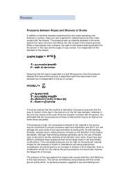
pressures Between Ropesand Sheaves or DrumsIn addition to bending stresses experienced by wire ropesoperating over sheaves or pulleys, ropes are also subjectedto radial pressure as they make contact with the sheave.This pressure sets up shearing stresses in the wires, distorts therope’s structure, and affects the rate of wear of the sheave grooves.When a rope passes over a sheave, the load on the sheavebearing results from the tension in the rope and the angle of ropecontact. It is independent of the diameter of the sheave.Load on bearing =2T sin θ2T = rope tension (pounds)θ = angle of rope contactAssuming that the rope is supported in a well-fitting groove,then the pressure between the rope and the groove isdependent upon the rope tension and diameter but isindependent of the arc of contact.2TPressure, P =DdP = pressure (psi)T = rope tension (pounds)D = diameter of sheave or drum (in)d = diameter of rope (in)It must be realized that this method of estimation of pressureassumes that the area of contact of the rope in the groove ison the full rope diameter, whereas in fact only the crowns ofthe outer wires are actually in contact with the groove. It isestimated that the local pressures at these contact points maybe as high as five times those calculated.If the pressure is high, the compressive strength of the materialin the groove may be insufficient to prevent excessive wearand indentation and this in turn will damage the outer wires ofthe rope and affect its working life. As with bending stresses,stresses due to radial pressure increase as the diameterof the sheave decreases. Although high bending stressesgenerally call for the use of flexible rope constructions havingrelatively small-diameter outer wires, these have less ability towithstand heavy pressures than do the larger wires in the lessflexible constructions. If the calculated pressures are too highfor the particular material chosen for the sheaves or drumsor indentations are being experienced, consideration shouldbe given to an increase in sheave or drum diameter. Such amodification would not only reduce the groove pressure, butwould also improve the fatigue life of the rope.Hardness of Rope WireRope gradeApproximate HardnessMinimum Tensile Strength Brinel Rockwell 'C'EEIP 444/486 46-50EIP 415/461 44-48IPS 388/444 42-46Recommended pulley hardness: 250-300 Brinell for Mn steel orequivalent alloy steel.Design Factor(Minimum Rope Breaking Strength /Maximum Load on Rope)Industry standards provide minimum design factors allowedfor certain rope applications. Some typical minimum designfactors follow:Mobile crane Hoist rope 3.5Hoist rope (rotation resistant) 5Boom hoist rope 3.5Wire rope slings 5Tower cranes 5Offshore pedestal cranes 5Drill lines 3Overhead cranes 5The pressure of the rope against the sheave also causesdistortion and flattening of the rope structure. This can becontrolled by using sheaves with the correct groove profilewhich, for general purposes, suggests a recommended groovediameter of nominal rope diameter +6%. The profile at thebottom of the groove should be circular over an angle ofapproximately 120°, and the angle of flare between the sides ofthe sheave should be approximately 52°.BRIDON North American Catalog 41
Technical InformationBend FatigueService life curve for various D:d ratiosBend fatigue testing of ropes usually consists of cycling a lengthof rope over a sheave while the rope is under a constant tension.As part of its ongoing development program, <strong>Bridon</strong> has testedliterally thousands of ropes in this manner over the years on itsown in-house design bend testing equipment.Through this work, <strong>Bridon</strong> has been able to compare the effectsof rope construction, tensile strength, lay direction, sheave size,groove profile and tensile loading on bend fatigue performanceunder ideal operating conditions. At the same time it has beenpossible to compare rope life to discard criteria (e.g., as laiddown in ISO 4309) with that to complete failure of the rope, i.e.,to the point where the rope has been unable to sustain the loadany longer. As part of the exercise, it has also been possible toestablish the residual breaking strength of the rope at discard levelof deterioration.Relative Rope Service Life10080604020005 10 15 20 25 30 35 40 45 50 55 60 65D:d ratioEffects of D:d Ratio and loading on fatigue lifeTypical example Dyform 6Number of bends to rope failure10% MBL20% MBL5% MBL30 29 28 27 26 25 24 23 22 21 20 19 18 17 16Sheave D:d ratioWhat needs to be recognized, however, is that very few ropesoperate under these controlled operating conditions, making it verydifficult to use this base information when attempting to predictrope life under other conditions. Other influencing factors, such asdynamic loading, differential loads in the cycle, fleet angle, reevingarrangement, type of spooling on the drum, change in ropedirection, sheave alignment, sheave size and groove profile, canhave an equally dramatic effect on rope performance.However, the benefit of such testing can be particularly helpful tothe rope manufacturer when developing new or improvingexisting products.If designers or operators of equipment are seeking optimum ropeperformance or regard bending fatigue life as a key factor in theoperation of equipment, such information can be provided by<strong>Bridon</strong> for guidance purposes.Oversize ToleranceWire ropes are manufactured slightly larger than the nominaldiameter. The maximum allowable oversize tolerances providedby industry standards are shown in the following table:Nominal Rope DiameterBending Ratios D:dUnderTypical minimum bending ratios (sheave or drum dia : ropedia) provided by some industry standards are as follows:DrumToleranceSheaveMobile crane Load hoist 18 18Boom hoist 15 15Load block 16Tower crane Hoist 18 18Load block 16Rotary drilling Drill Line 20 20Offshore pedestal crane Hoist 18 18Surface mining Hoist 24 24Drag 22 22OverUp to 1/8" -0 +8%Over 1/8” to 3/16" -0 +7%Over 3/16” to 5/16" -0 +6%Over 5/16" -0 +5%42 BRIDON North American Catalog
The Use of Swivels with Wire RopeUnder certain circumstances it may be necessary to use a swivel ina lifting system to prevent rotation of the load. This is typically donefor employee safety considerations. It is possible however, that theuse of a swivel will have an adverse affect on rope performanceand may in some cases damage the wire rope.There are many types of accessories available that incorporatedifferent types and degrees of rotation preventing swivels. Theswivel may be either an independent accessory or an integralpart of a lifting device such as a crane block with a swivel hook. Atypical independent accessory is a ball bearing anti-friction swivel.There are also headache balls with swivel hooks.The type of swivel that causes the most concern from thestandpoint of the wire rope is the independent anti-frictionswivel that attaches directly to the rope. The purpose of using aswivel in a lifting system is to prevent rotation of the load. Thisthen allows the wire rope to rotate. Excessive rope rotation candamage a wire rope.To assist in determining whether or not a swivel should be usedin the lifting system, the following recommendations shouldbe considered. It must also be recognized that the rotationcharacteristics of different types and constructions of wire rope varyconsiderably. The following types and constructions of wire ropeare grouped according to their rotation characteristics.<strong>Group</strong> 1Wire rope constructions having very high rotation characteristicsshould not be used with a swivel under any circumstances.These rope constructions will rotate excessively with one end freeto rotate and the rope will unlay and distort and be easily damagedwith a loss of rope breaking force.• Blue Strand 6x19 and 6x36 Class Lang Lay• All constructions of Triangular (flattened) Strand Lang Lay• Endurance Dyform 8 Lang Lay• Constructex<strong>Group</strong> 3a and 3bThe ropes in this <strong>Group</strong> are designed with an inner rope that is laidin the opposite direction to the outer strands to provide a mediumresistance to rotation. Ropes with medium rotation characteristicsare used with a swivel in single part reeving applications. However,a swivel is not recommended for multiple-part hoisting applicationsor in any application where the swivel is not necessary for safetyreasons. If it is necessary to use a swivel the rope must beoperating within the design factor of 5, must not be shock loadedand must be inspected daily by a qualified person for distortion.It should be noted that if a swivel is used in conjunction with <strong>Group</strong>3a ropes, rope service life might be reduced due to increasedinternal wear between the outer strands and the inner rope.<strong>Group</strong> 3a - Endurance 8RR Rotation Resistant- Endurance 19 Rotation Resistant<strong>Group</strong> 3b - Endurance Dyform 18 Rotation Resistant<strong>Group</strong> 4Wire ropes having low rotation characteristics used in either singleor multiple part reeving may be used with a swivel. The reason forthis is that the ropes will exhibit very little, if any, rotation when usedat the proper design factor. Application parameters such as a fleetangle may induce turn into a wire rope that can be relieved by theuse of a swivel. However, if the application does not induce anyturn into the rope or if a swivel is not beneficial to the performanceof the rope the swivel may not be necessary.• Endurance 35 LS• Endurance Dyform34LR /PI/MAXNOTE: When using a swivel with any wire rope, frequent inspection ofthe rope is necessary. The rope should not be shock loaded oroverloaded.<strong>Group</strong> 2Wire rope constructions having high rotation characteristics whenused in single part reeving may require a swivel in the systemto prevent rotation in certain operating conditions. However, thisshould be done only when employee safety is the issue.These rope constructions when used in a reeving system withone end free to rotate will have a high level of rotation. This willcause the rope to unlay to some degree and distortion of therope will occur.• Blue Strand 6x19 and 6x36 Class Regular Lay• Endurance Dyform 6 and 8 Regular LayBRIDON North American Catalog 43
Technical InformationFleet AngleOf all the factors that have some influence on the winding ofa rope on a smooth drum, the fleet angle, arguably, has thegreatest effect.Fleet angle is usually defined as the included angle betweentwo lines, one that extends from a fixed sheave to the flange ofa drum and the other that extends from the same fixed sheaveto the drum in a line perpendicular to the axis of the drum.(See illustration.)Illustration of Fleet AngleAt the sheaveWhere a fleet angle exists as the rope enters a sheave, it initially makescontact with the sheave flange. As the rope continues to pass throughthe sheave, it moves down the flange until it sits in the bottom of thegroove. In doing so, even when under tension, the rope will actually rollas well as slide. As a result of the rolling action, the rope is twisted, i.e.,turn is induced into or out of the rope, either shortening or lengtheningthe lay length of the outer layer of strands. As the fleet angle increasesso does the amount of twist.To reduce the amount of twist to an acceptable level, the fleet angleshould be limited to 2.5° for grooved drums and 1.5° for plain drums,and when using rotation-resistant ropes, the fleet angle should belimited to 1.5°.Fleet angleSheaveHowever, for some crane and hoist applications it is recognizedthat for practical reasons it is not always possible to comply withthese general recommendations, in which case the rope life couldbe affected.DrumIf the drum incorporates helical grooving, the helix angle of thegroove needs to be added or subtracted from the fleet angle asdescribed above to determine the actual fleet angle experiencedby the rope.At the drumWhen spooling rope onto a drum, it is generally recommendedthat the fleet angle is limited to between 0.5° and 2.5°. If the fleetangle is too small, i.e., less than 0.5°, the rope will tend to pileup at the drum flange and fail to return across the drum. In thissituation, the problem may be alleviated by introducing a kickerdevice or by increasing the fleet angle through the introductionof a sheave or spooling mechanism.If the rope is allowed to pile up, it will eventually roll awayfrom the flange, creating a shock load in both the rope andthe structure of the mechanism; an undesirable and unsafeoperating condition.Excessively high fleet angles will return the rope across thedrum prematurely, creating gaps between wraps of rope closeto the flanges as well as increasing the pressure on the rope atthe crossover positions.Even where helical grooving is provided, large fleet angles willinevitably result in localized areas of mechanical damage asthe wires "pluck" against each other. This is often referred to as"interference," but the amount can be reduced by selecting aLangs lay rope if the reeving allows. The interference effect canalso be reduced by employing a Dyform rope, which offers amuch smoother exterior surface than conventionalrope constructions.Floating sheaves or specially designed fleet anglecompensating devices may also be employed to reduce thefleet angle effect.44 BRIDON North American CatalogRope TorqueThe problem of torsional instability in crane hoist ropes would not existif the ropes could be perfectly torque balanced under load. The torquegenerated in a wire rope under load is usually directly related to theapplied load by a constant torque factor. For a given rope construction,the torque factor can be expressed as a proportion of the ropediameter and this has been done below.Variation with rope construction is relatively small, and hence thescope for dramatically changing the stability of a hoisting systemis limited. Nevertheless the choice of the correct rope can have adeciding influence, especially in systems that are operating close tothe critical limit. It should be noted that the rope torque referred tohere is purely that due to tensile loading. No account is taken of thepossible residual torque due, for example, to rope manufacture orinstallation procedures.Torsional StabilityTorsional stability and the cabling graph (see page 46) are twomethods that can be used to determine torsional stability or thetendency of the rope to cable. The torque factors quoted on page 47are approximate maximum values for the particular constructions. Tocalculate the torque value for a particular rope size multiply by thenominal rope diameter. Example: for 20 mm dia. Dyform 34LR at 20%of minimum breaking forceTorque value= torque factor x rope dia.= 0.76% x 20 mm= 0.152 mmTo calculate the torque generated in a particular rope when subjectedto a tensile load, multiply the load by the torque value and combinethe units.Example: for 20 mm dia. Dyform 34LR at 6000 kgf loadTorque generated= torque value x load= 0.152 . 6000= 912 kgf.mm
The torsional characteristics of wire rope will have the effect ofcausing angular displacement of a sheave block when used inmulti-fall reeving arrangements. The formula below gives a goodapproximation under such arrangements.S 2 = 4000L. Tvsin θWhere S is the rope spacing in mmL is the length of each part in the reevingTv is the torque value of the ropeθ is the angular displacement of the sheave blockWhen the angular displacement of the sheave block exceeds90° (sin θ = 1) torsional instability results and cabling of thereeving will occur. Therefore the test for stability of any particularreeving can be expressed as:WhereS >4 000 L. TvS is the rope spacing in mmL is length of each part in metersTv is torque value in mmThe preceding equations are all relative to a simple two partreeving. For more complex systems a similar approach may beused if account is taken of the different spacings of the ropes.Even Number of FallsRope PlanEffective RopeSpacingS=(X + Y)½Stable condition ifS > 4 000 . L. TvAngular displacement of blockTo predict the amount of angular displacement by which asheave block may turn under the influence of rope torque:sin θ = (4 000 L. Tv)S 2(for even number of falls)The equations assume that rope is torque-free in the no-loadcondition, therefore, induced torque during or immediately afterinstallation will adversely influence the calculated effect.The above data assumes a constant torque value which is avalid assumption for a new rope. Wear and usage can havea significant effect on the torque value but practical workshows that under such circumstances the torque value willdiminish, thus improving the stability of the arrangement. Somearrangements may be of such complexity that the evaluationdemands a computer study.Examples:Assuming a pedestal crane working on two falls is roped with20 mm diameter Dyform 34LR and the bottom block carries asheave of 360 mm diameter with the falls parallel:Torque value = 0.76% x 20= 0.152 mmIf the rope is new (worst condition) and no account is taken ofblock weight and friction, then angular displacement for a heightof lift of 30 meters is given bysin θ = (4 000 . 30 . 0.152)360 2= 0.141 i.e. 8° 10'The reeving would be expected to cable at a height of liftcalculated as:Note: For hoisting arrangements in which the rope falls arenot parallel an average rope spacing should be used.Uneven Number of Falls(Rope termination at bottom block)Rope PlanL = S 24 000 . Tv= 360 24 000 . 0.152= 213 metresFrom the crane designer’s viewpoint a safety factor against cablingshould be recognized (angular displacement limited at 30°) hencethe practical height of lift is approximately 106.5 meters.Effective Rope Spacing and modified formulafor stable conditionEffective Rope Spacing SBRIDON North American Catalog 45
Technical InformationCabling graphField research jointly conducted by the Wire Rope TechnicalBoard and the Power Crane and Shovel Association hasshown that cabling of the rope parts in a multiple-part reevedhoisting arrangement is controlled by several factors. Thefollowing calculations and graphs can be used to determinewhen and if cabling will occur on multiple-part reevedhoisting arrangements.S is determined as followsS = Spacing (Ft)2 part 3 partS2/3 of 2 partThe graph illustrates two-dimensional ratios. They are:1. L/s = Length of fall per unit rope spacing2. D/d = Average pitch diameter of traveling and crown blocksheave per unit rope diameterVarious constructions of rope shown on the graph indicatethe limited conditions for torsional stability with the angulardisplacement of the hoist block to a maximum of 90°. When theoperating conditions for a particular installation give a resultantabove the appropriate band, then cabling of the falls will mostlikely occur. If the operating conditions give a resultant belowany particular band, the cabling of the falls will most likely notoccur. If the operating conditions for any particular installationfall within the band, cabling is unpredictable.3004 part 5 part4/5 of 4 partS6 part 7 part6/7 of 6 partL/s250200150Stable if below bandUnstable if above bandUncertain if in bandS100505 10 15 20 25 30D/d1 Band 1 6x19 and 6x36 Class ropes, Endurance Dyform 6 and 82 Band 2 Endurance 8RR3 Band 3 Endurance Dyform 18, Endurance 194 Band 4 Endurance Dyform 34LR, Endurance 35LSL = length of fall (ft)s = average rope spacing (ft)D = average pitch diameter of point and block sheaves (in)d = nominal rope diameter (in)46 BRIDON North American Catalog
Summary Technical Information and Conversion Factors(For guidance purposes only)<strong>Bridon</strong> supplies a range of Endurance high performance steel wire ropes specifically designed and manufactured to meet the needsof today’s cranes and the demanding applications to which they are exposed. High performance ropes are normally selected bycustomers when they require the specific characteristics of improved performance, high strength, low extension, or low rotation.Rope ConstructionFillFactor%Rope modulus at 20%of breaking forcepsiExtension characteristicsInitial permanentextension%Torque factor at 20%of breaking force%Rotational characteristicsTurn value at 20%of breaking forcedegrees/rope lay6 & 8 Strand High performanceEndurance Dyform 6 69.0 13,500,000 0.10 7.50 58Endurance Dyform 8 66.2 12,600,000 0.15 8.74 91Endurance Dyform 8PI 66.8 12,600,000 0.16 9.55 94Rotation-ResistantEndurance 19 61.3 10,000,000 0.24 6.60 5Endurance Dyform 18 72.8 14,000,000 0.09 4.50 4Endurance Dyform 18PI 71.1 14,000,000 0.11 3.80 2.6Endurance 35ls 63.8 14,000,000 0.10 0.76 0.2Endurance Dyform 34lr/34LRPI 77.3 14,500,000 0.05 0.76 0.2Conventional ConstructionsBlue Strand 6x36 61.7 12,600,000 0.17 7.75 56Blue Strand 6x19 62.4 13,500,000 0.15 7.10 42Conversion Factors S.I. unitsForce1 kN = 0.101 972 Mp 1 UK tonf = 9.964.02 N 1 kg = 2.204 62 lb 1 lb = 0.453 592 kg1 N = 0.101 972 kgf 1 lbf = 4.448 22 N 1 tonne (t) = 0.984 207 UK ton 1 UK ton = 1.01605 tonnes (t)1 kgf = 9.806 65 N 1 lbf = 0.453 592 kgf 1 kg/m = 0.671 970 lb/ft 1 lb/ft = 1.488 kg/m1 kgf = 1 kp 1 UK tonf = 1.01605 tonne 1 kg = 1000 g 1 kip (USA) = 1000 lb1 N = 1.003 61 x 10 4 UK tonf 1 UK tonf = 9.964 02 kN 1 Mp = 1 x 10 6 g1 N = 0.2244 809 lbf 1 UK tonf = 2240 lbf1 kgf = 2.204 62 lbf 1 short tonf Length1 t = 0.984 207 UK tonf (USA) = 2000 lbf 1 m = 3.280 84 ft 1 ft = 0.304 8 m1 kN = 0.100 361 UK tonf 1 kip (USA) = 1000 lbf 1 km = 0.621 371 miles 1 mile = 1.609 344 km1 kip = 453.592 37 kgfpressure/Stress1 N/mm 2 = 0.101972 kgf/mm 2 1 mm 2 = 0.001 55 in 2 1 in 2 = 645.16 mm 21 kgf/mm 2 = 9.806 65 N/mm 2 1 m 2 = 10.763 9 ft 2 1 ft 2 = 0.092 903 0 m 21 N/mm 2 = 1 MPa1 kgf/mm 2 = 1 422.33 lbf/in 2 1 lbf/in 2 = 7.030 x 10 -4 kgf/mm 2 Volume1 kgf/mm 2 = 0.634 969 tonf/in 2 1 tonf/in 2 = 1.574.88 kgf/mm 2 1 cm 3 = 0.061 023 7 in 3 1 in 3 =16.387 1 cm 31 N/m 2 = 1.450 38 x 10 -4 lbf/in 2 1 lbf/in 2 = 6.894.76 N/m 2 1 litre (1) = 61.025 5 in 3 1 in 3 = 16.386 6 ml1 N/m 2 = 1 x 10 -6 N/mm 2 1 tonf/in 2 = 1.544 43 x 10 8 dyn/cm 2 1 m 3 = 6.102 37 x 104 in 3 1 yd 3 = 0.764 555 m 31 bar = 14.503 8 lbf/in 21 hectobar = 10 N/mm 2MassArea1 hectobar = 10 7 N/m 2 BRIDON North American Catalog 47
Guide to Examinationguide to ExaminationThe continued safe operation of lifting equipment, liftingaccessories (e.g., slings) and other systems employingwire rope depends to a large extent on the operation ofwell-programmed periodic rope examinations and theassessment by the competent person of the fitness of therope for further service.Some of the More Common Types ofWire Fractures Can Include:ASevered bywearB Tension C Fatigue D CorrosionfatigueExamination and discard of ropes by the competent personshould be in accordance with the instructions given in theoriginal equipment manufacturer’s handbook. In addition,account should be taken of any local or applicationspecific regulations.The competent person should also be familiar, as appropriate,with the latest versions of related ASME B30, International,European, or National standards.particular attention must be paid to those sections of ropewhich experience has shown to be liable to deterioration.Excessive wear, broken wires, distortions and corrosion arethe more common visible signs of deterioration (see below).Note: This publication has been prepared as an aid for rope examinationand should not be regarded as a substitute for the competent person.Wear is a normal feature of rope service and the use of thecorrect rope construction ensures that it remains a secondaryaspect of deterioration. Lubrication may help to reduce wear.Broken wires are a normal feature of rope service towards theend of the rope’s life, resulting from bending fatigue and wear.The local breakup of wires may indicate some mechanical faultin the equipment. Correct lubrication in service will increasefatigue performance.E Plastic wear F Martensite gSheared endDistortions are usually a result of mechanical damage, and ifsevere, can considerably affect rope strength.Visible rusting indicates a lack of suitable lubrication, resulting incorrosion. Pitting of external wire surfaces becomes evident insome circumstances. Broken wires ultimately result.Internal corrosion occurs in some environments whenlubrication is inadequate or of an unsuitable type. Reductionin rope diameter will frequently guide the observer to thiscondition. Confirmation can only be made by opening the ropewith clamps or the correct use of spike and needle to facilitateinternal inspection.Note: Non-destructive testing (NDT) using electromagnetic means mayalso be used to detect broken wires and/or loss in metallic area. Thismethod complements the visual examination but does not replace it.pictures courtesy of S.M.R.E. Crown Copyright 1966Factors Affecting Rope performanceMulti-layers of the rope on the drum can result in severedistortion in the underlying layers.Bad spooling (due to excessive fleet angles or slackwinding) can result in mechanical damage, shown as severecrushing, and may cause shock loading during operation.Small-diameter sheaves can result in permanent set ofthe rope, and will certainly lead to early wire breaks.Oversize grooves offer insufficient support to the ropeleading to increased localized pressure, flattening of therope and premature wire fractures. Grooves are deemedto be oversize when the groove diameter exceeds thenominal rope diameter by more than 15%.Undersize grooves in sheaves will crush and deformthe rope, often leading to two clear patterns of wear andassociated wire breaks.Excessive angle of fleet can result in severe wear of therope due to scrubbing against adjacent laps on the drum.Rope deterioration at the termination may be exhibited inthe form of broken wires. An excessive angle of fleet canalso induce rotation causing torsional imbalance.48 BRIDON North American Catalog
Typical Examples of Wire Rope Deterioration1Mechanical damage due9Typical wire fracturesto rope movement overas a result of bendsharp edge projectionfatigue.while under load.2Localized wear due10Wire fractures atto abrasion onthe strand, or coresupporting structure.interface, as distinctfrom "crown" fractures.3Narrow path of wear11Breakup of IWRCresulting in fatigueresulting from highfractures, caused bystress application.working in a grosslyoversize groove, or oversmall support rollers.4Two parallel paths of12Looped wires as abroken wires indicativeresult of torsionalof bending through animbalance and/orundersize groove inshock loading.the sheave.5Severe wear,13Typical exampleassociated withof localized wearhigh tread pressure.and deformation.6Severe wear in14Multi-strand ropeLangs Lay, caused"bird caged" due toby abrasion.torsional imbalance.7Severe corrosion.15Protrusion of ropecenter resulting frombuildup of turn.8Internal corrosion while16Substantial wearexternal surface showsand severe internallittle evidencecorrosion.of deterioration.BRIDON North American Catalog 49
Troubleshooting GuideThe following is a simplified guide to common wire rope problems. In the event of no other standard being applicable,<strong>Bridon</strong> recommends that ropes are inspected/examined in accordance with ASME B30.5.problemMechanical damage caused by the rope contacting the structure of thecrane on which it is operating or an external structure — usually of alocalized nature.Cause/Action• Generally results from operational conditions.• Check sheave guards and support/guide sheaves to ensure that the rope has not“jumped out” of the intended reeving system.• Review operating conditions.• Check sheave and drum groove radii using sheave gauge to ensure that they are nosmaller than nominal rope radius +2.5%. <strong>Bridon</strong> recommends that the sheave anddrum groove radii are checked prior to any rope installation.• Repair or replace drum/sheaves if necessary.Opening of strands in rotation-resistant ropes — in extreme circumstances therope may develop a “birdcage distortion” or protrusion of inner strands.Note — rotation-resistant ropes are designed with a specific strand gap whichmay be apparent on delivery in an off tension condition. These gaps will closeunder load and will have no effect on the operational performance of the rope.• Check fleet angles in the reeving system — a fleet angle in excess of 1.5 degreesmay cause distortion (see page 56).• Check installation method — turn induced during installation can cause excessiverope rotation resulting in distortion (see pages 55 to 58).• Check if the rope has been cut on site prior to installation or cut to remove adamaged portion from the end of the rope. If so, was the correct cutting procedureused? Incorrect cutting of rotation-resistant, low-rotation and parallel closed ropescan cause distortion in operation (see page 56 to 57).• Rope may have experienced a shock load.Broken wires or crushed or flattened rope on lower layers at crossover pointsin multi-layer coiling situations.Wire breaks usually resulting from crushing or abrasion.• Check tension on underlying layers. <strong>Bridon</strong> recommends an installation tension ofbetween 2% and 5% of the minimum breaking force of the wire rope. Care shouldbe taken to ensure that tension is retained in service. Insufficient tension will result inthese lower layers being more prone to crushing damage.• Review wire rope construction. Dyform wire ropes are more resistant to crushing onunderlying layers than conventional rope constructions.• Do not use more rope than necessary.• Check drum diameter. Insufficient bending ratio increases tread pressure.• Insufficient service dressing.• Consider alternative rope construction.Wires looping from strands.• If wires are looping out of the rope underneath a crossover point, there may beinsufficient tension on the lower wraps on the drum.• Check for areas of rope crushing or distortion.• Possible fleet angle problems causing rope rotation.“pigtail” or severe spiralling in rope.• Check that the sheave and drum diameter is large enough. <strong>Bridon</strong> recommends aminimum ratio of the drum/sheave to nominal rope diameter of 18:1.• Indicates that the rope has run over a small radius or sharp edge.• Check to see if the rope has “jumped off” a sheave and has run over a shaft.50 BRIDON North American Catalog
problemTwo single axial lines of broken wires running along the length of the ropeapproximately 120 degrees apart indicating that the rope is being nipped in atight sheave.Cause/Action• Check sheave and drum groove radii using sheave gauge to ensure that they areno smaller than nominal rope radius + 2.5%. <strong>Bridon</strong> would recommend that thesheave/drum groove radii are checked prior to any rope installation.• Repair or replace drum/sheaves if necessary.One line of broken wires running along the length of the rope indicatinginsufficient support for the rope, generally caused by oversize sheave ordrum grooving.• Check to see if the groove diameter is no greater than 15% greater than the nominalrope diameter.• Repair or replace drum/sheaves if necessary.• Check for contact damage.Short rope life resulting from evenly/randomly distributed bend fatigue wirebreaks caused by bending through the reeving system.Fatigue-induced wire breaks are characterized by flat ends on thebroken wires.• Bending fatigue is accelerated as the load increases and as the bending radiusdecreases (see page 42). Consider whether either factor can be improved.• Check wire rope construction. Dyform ropes are capable of doubling the bendingfatigue life of a conventional steel wire rope.• Bending fatigue is accelerated as the load increases and as the bending radiusdecreases (see page 42). Consider whether either factor can be improved.Short rope life resulting from localized bend fatigue wire breaks.Fatigue-induced wire breaks are characterized by flat ends on thebroken wires.• Check wire rope construction. Dyform ropes are capable of doubling the bendingfatigue life of a conventional steel wire rope.• Localized fatigue breaks indicate continuous repetitive bends over a short length.Consider whether it is economical to periodically shorten the rope in order to movethe rope through the system and progressively expose fresh rope to the severebending zone. In order to facilitate this procedure it may be necessary to beginoperating with a slightly longer length of rope.Broken rope — ropes are likely to break when subjected to substantialoverload or misuse particularly when a rope has already been subjected tomechanical damage.Corrosion of the rope both internally and/or externally can also result in asignificant loss in metallic area. The rope strength is reduced to a level whereit is unable to sustain the normal working load.• Review operating conditions.• Check sheave and drum groove radii using sheave gauge to ensure that they are nosmaller than nominal rope radius +2.5%. <strong>Bridon</strong> recommends that the sheave/drumgroove radii are checked prior to any rope installation.Wave or corkscrew deformations normally associated withrotation-resistant ropes.• Repair or replace drum/sheaves if necessary.• Check fleet angles in the reeving system — a fleet angle in excess of 1.5 degreesmay cause distortion (see page 44)• Check that rope end has been secured in accordance with manufacturer'sinstructions (see page 56 and 57).• Check operating conditions for induced turn.Rotation of the load in a single fall system.• Review rope selection.• Consider use of rotation-resistant rope.Rotation of the load in a multi-fall system resulting in “cabling” of the rope falls.possibly due to induced turn during installation or operation.• Review rope selection (see page 44 to 46 cabling calc.)• Consider use of rotation-resistant rope.• Review installation procedure (see page 55 to 58) or operating procedures.BRIDON North American Catalog 51
Troubleshooting GuideproblemCore protrusion or broken core in single layer six– or eight-strand rope.Cause/Action• Caused by repetitive shock loading — review operating conditions.Rope accumulating or “stacking” at drum flange due to insufficientfleet angle.• Review drum design with original equipment manufacturer — consider adding ropekicker, fleeting sheave, etc.• Check correct rope diameter.• If grooved drum check groove pitch.Sunken wraps of rope on the drum normally associated with insufficientsupport from lower layers of rope or grooving.• Check tension on underlying layers. <strong>Bridon</strong> recommends an installation tension ofbetween 2% and 5% of the minimum breaking force of the wire rope. Care shouldbe taken to ensure that tension is retained in service. Insufficient tension will result inthese lower layers being more prone to crushing damage.• Make sure that the correct rope length is being used. Too much rope (which maynot be necessary) may aggravate the problem.• Check fleet angle to drum.• Check general alignment of sheaves in the reeving system.Short rope life induced by excessive wear and abrasion.• Check that all sheaves are free to rotate.• Review rope selection. The smooth surface of Dyform wire ropes gives bettercontact with drum and sheaves and offers improved resistance to interferencebetweeen adjacent laps of rope.External corrosion.• Consider selection of galvanized rope.• Review level and type of service dressing.• Consider selection of galvanized rope.Internal corrosion.• Review frequency amount and type of service dressing.• Consider selection of plastic impregnated (PI) wire rope.52 BRIDON North American Catalog
Product Safety: Instructions and warnings onthe use of steel wire ropeThe following instructions and warnings combine to provideguidance on product safety and are intended for use by thosealready having a working knowledge of wire ropes, as well asthe new user. They should be read, followed and passed onto others.Failure to read, understand and follow these instructions couldresult in harmful and damaging consequences.1. Rope Selection CriteriaEnsure that the correct type of wire rope is selectedfor the equipment by referring to the OEM’s instructionmanual or other relevant documents. If in doubt contact<strong>Bridon</strong> for guidance.1.1 Rope strengthIf necessary, refer to the appropriate regulations and/orapplication standards and calculate the maximum force towhich the rope will be subjected.The calculation may take into account the mass to belifted or moved, any shock loading, effects of high speed,acceleration, any sudden starts or stops, frequency ofoperation and sheave bearing friction.By applying the relevant design factor and, whereapplicable, the efficiency of the rope termination, therequired minimum breaking load or force of the rope willbe determined, the values of which are available fromthe relevant national or international standards or fromspecific product data literature. If in doubt ask for advicefrom <strong>Bridon</strong>.1.2 Bending fatigueThe size and number of sheaves in the system willinfluence the performance of the rope.Wire rope that bends around sheaves, rollers or drums will deterioratethrough bending fatigue. Reverse bending and high speed willaccelerate the process. Therefore, under such conditions select a ropewith high bending fatigue resistance. Refer to product data information,and if in doubt ask for advice.1.3 AbrasionWire rope that is subject to abrasion will becomeprogressively weaker as a result of:Externally — dragging it through overburden, sand orother abrasive materials and passing around a sheave,roller or drum.Internally — being loaded or bent.Abrasion weakens the rope by removing metal from both the inner andouter wires. Therefore, a rope with large outer wires should normallybe selected.1.4 VibrationVibration in wire rope will cause deterioration. This maybecome apparent in the form of wire fractures where thevibration is absorbed.These fractures may be internal only and will not be visually identified.1.5 DistortionWire rope can be distorted due to high pressure againsta sheave, improperly sized grooves, or as a result ofmulti-layer spooling on a drum.Rope with a steel core is more resistant to crushingand distortion.1.6 CorrosionRope with a large number of small wires is moresusceptible to corrosion than rope with a small numberof large wires. Therefore, if corrosion is expected to havea significant effect on rope performance. The rope mayhave to be lubricated frequently in service or a galvanizedrope may be selected.1.7 CablingCabling of rope reeving due to block rotation can occurif the rope is incorrectly selected. Applications involvinghigh lifts are particularly vulnerable to this condition,therefore, ropes specifically designed to resist rotationneed to be selected.1.8 Fixing of rope endsRopes that have high rotation characteristics must notbe selected unless both ends of the rope are fixed or theload is guided and unable to rotate.1.9 Connecting ropesIn the event that it is necessary to connect one ropeto another (in series) it is essential that they have therequired strength, are of the same type and have thesame lay direction (i.e., connect right lay to right lay).Failure to heed this warning could result in catastrophic failureparticularly at a termination that is capable of being pulled apart (i.e.,splice) due to unlaying.1.10 Rope lengthRope length and/or difference in length between two ormore ropes used in a set may be a critical factor andmust be considered along with rope selection.Wire rope will elongate under load. Other factors such as temperature,rope rotation and internal wear will also have an effect. These factorsshould also be considered during rope selection.BRIDON North American Catalog 53
Product Safety: Instructions and warnings onthe use of steel wire rope1.11 Preformed and non-preformed ropesSingle layer round-strand rope is normally suppliedpreformed. However, if a non-preformed rope is selectedthen personnel responsible for its installation and/ormaintenance need to take particular care when handlingsuch rope, especially when cutting. For the purposesof this instruction, rotation-resistant ropes should beregarded as non-preformed ropes.1.12 Operating temperaturesWire rope with a steel core should be selected if there isany evidence to suggest that a fiber core will not provideadequate support to the outer strands and/or if thetemperature of the working environment may be expectedto exceed 180˚F.For operating temperatures above 200˚F de-rating of theminimum breaking force of the rope is necessary (e.g.,between 200˚F and 400˚F reduce by 10%; between200˚C and 300˚C reduce by 25%; between 600˚F and800˚F reduce by 35%).Do not use ropes with high carbon wires above 800˚F.Failure to observe this general guidance could result in failure of theropes to support the load.For temperatures over 800˚F, other materials suchas stainless steel or other special alloys should beconsidered.Rope lubricants and any synthetic filling and/or covering materials maybecome ineffective at certain low or high operating temperature levels.Certain types of rope end terminations also have limitingoperating temperatures and the manufacturer or <strong>Bridon</strong>should be consulted where there is any doubt. Ropeswith aluminium ferrules must not be used at temperaturesin excess of 300˚F.2. Storage2.1 Unwrap the rope and examine the rope immediately afterdelivery to check its identification and condition and verifythat it is in accordance with the details on the certificatesand/or other relevant documents.Check the rope diameter and examine any ropeterminations to ensure that they are compatible with theequipment or machinery to which they are to be fitted.2.2 Select a clean, well-ventilated, dry, undercover location.Cover with waterproof material if the delivery siteconditions preclude inside storage.Rotate the reel periodically during long periods of storage,particularly in warm environments, to prevent migration ofthe lubricant from the rope.Never store wire rope in areas subject to elevated temperatures asthis may seriously affect its future performance. In extreme cases itsoriginal as-manufactured strength may be severely reduced rendering itunfit for safe use.Ensure that the rope does not make any direct contactwith the floor and that there is a flow of air under the reel.Failure to do so may result in the rope becoming contaminated withforeign matter and start the onset of corrosion before the rope is evenput to work.Support the reel on a simple A-frame or cradle, locatedon ground that is capable of supporting the total massof rope and reel. Ensure that the rope is stored where itis not likely to be affected by chemical fumes, steam orother corrosive agents.Failure to do so may seriously affect its condition rendering it unfit forsafe use.2.3 Examine ropes in storage periodically and, whennecessary, apply a suitable dressing that is compatiblewith the manufacturing lubricant. Contact the ropesupplier, <strong>Bridon</strong> or original equipment manufacturer’s(OEM) manual for guidance on types of dressingsavailable, methods of application and equipment for thevarious types of ropes and applications.Re-wrap the rope unless it is obvious that this will bedetrimental to rope preservation.Failure to apply the correct dressing may render the originalmanufacturing lubricant ineffective and rope performance may besignificantly affected.Ensure that the rope is stored and protected in sucha manner that it will not be exposed to any accidentaldamage either during the storage period or when placingthe rope in, or taking it out of storage.Failure to carry out or pay attention to any of the above could result in aloss of strength and/or a reduction in performance. In extreme cases therope may be unfit for safe use.54 BRIDON North American Catalog
3. Certification and Marking3.1 Make sure that the relevant certificate has been obtainedbefore taking the rope into use for a lifting operation.Check to verify that the marking on the rope or itspackage matches the relevant certificate.Note: The rating of a component part of a machine or liftingaccessory is the responsibility of the designer of the machineor accessory. Any re-rating of a lifting accessory must beapproved by a competent person.3.2 Retain the certificate in a safe place for identificationof the rope when carrying out subsequent periodicstatutory examinations in service.4. Handling and Installation4.1 Handling and installation of the rope should be carriedout in accordance with a detailed plan and should besupervised by a competent person.Incorrectly supervised handling and installation procedures may resultin serious injury to persons in the vicinity of the operation as well asthose persons directly involved in the handling and installation.4.2 Wear suitable protective clothing such as overalls,industrial gloves, helmet, eye protectors, and safetyfootwear (and respirator, particularly where the emissionof fumes due to heat is likely).Failure to wear suitable protective clothing and equipment may resultin skin problems from overexposure to certain types of rope lubricantsand dressings; burns from sparks, rope ends, molten lubricants, andmetals when cutting ropes or preparing sockets for reuse; respiratory orother internal problems from the inhalation of fumes when cutting ropesor preparing sockets for reuse; eye injuries from sparks when cuttingropes; lacerations to the body from wire and rope ends; bruising of thebody and damage to limbs due to rope recoil, backlash and any suddendeviation from the line of path of rope.4.3 Ensure that the correct rope has been supplied bychecking to see that the description on the certificate is inaccordance with that specified in the purchaser’s order.4.4 Check by measurement that the nominal diameter ofthe new rope conforms to the nominal size stated onthe certificate.For verification purposes, measure the diameter by usinga suitable rope vernier fitted with jaws broad enough tocover not less than two adjacent strands. Take two sets ofmeasurements spaced at least 3' apart, ensuring that theyare taken at the largest cross-sectional dimension of therope. At each point take measurements at right angles toeach other.The average of these four measurements should bewithin the tolerances specified in the appropriate standardor specification.For a more general assessment of rope diameter use arope calliper.4.5 Examine the rope visually to ensure that no damage orobvious signs of deterioration have taken place duringstorage or transportation to the installation site.4.6 Check the working area around the equipment for anypotential hazards that may affect the safe installation ofthe rope.4.7 Check the condition of the rope-related equipmentin accordance with the OEM’s instructions. Includethe following:DrumCheck the general condition of the drum.If the drum is grooved, check the radius and pitchand ensure that the grooves will satisfactorilyaccommodate the size of the new rope.Check the condition and position of the kicker platesor wear plates, if fitted, to ensure that the new rope willspool correctly on the drum.SheavesEnsure that the grooving is of the correct shape andsize for the new rope.Check that all sheaves are free to rotate and ingood condition.Rope guardsCheck that any rope guards are correctly fitted and arein good condition.Check the condition of any wear plates or rollers whichare protecting structural members.Failure to carry out any of the above could result in unsatisfactory andunsafe rope performance.Note: Grooves must have clearance for the rope and provideadequate circumferential support to allow for free movement ofthe strands and facilitate bending. When grooves become wornand the rope is pinched at the sides, strand and wire movementis restricted and the ability of the rope to bend is reduced.4.8 When a new rope is fitted a variation in size comparedwith the old worn rope will be apparent. The new ropemay not fit correctly into the previously worn grooveprofile and unnecessary wear and rope distortion is likelyto occur. This may be remedied by machining out thegrooves before the new rope is installed. Before carryingout such action the sheaves or drum should be examinedto ensure that there will be sufficient strength remaining inthe underlying material to safely support the rope.BRIDON North American Catalog 55
Product Safety: Instructions and warnings onthe use of steel wire ropeThe competent person should be familiar with therequirements of the appropriate application/machinerystandard.Note: General guidance to users is given in the Wire RopeUsers Manual.Transfer the wire rope carefully from the storage area tothe installation site.CoilsPlace the coil on the ground and roll it out straight,ensuring that it does not become contaminated withdust/grit, moisture, or any other harmful material.If the coil is too large to physically handle, it may beplaced on a swift turntable and the outside end of therope pulled out allowing the coil to rotate.Never pull a rope away from a stationary coil as this will induceturn into the rope and kinks will form. These will adversely affectrope performance.ReelsPass a shaft through the reel and place the reel in asuitable stand which allows it to rotate and be brakedto avoid overrun during installation. Where multi-layercoiling is involved it may be necessary for the reelto be placed in equipment which has the capabilityof providing a back tension in the rope as it is beingtransferred from reel to drum. This is to ensure that theunderlying (and subsequent) laps are wound tightly onthe drum.- Position the reel and stand such that the fleet angleduring installation is limited to 1.5 degrees.- If a loop forms in the rope, ensure that it does nottighten to form a kink.A kink can severely affect the strength of a six-strand rope andcan result in distortion of a rotation-resistant rope leading to itsimmediate discard.Ensure that the reel stand is mounted so as not to createa reverse bend during reeving (i.e., for a winch drum withan overlap rope, take the rope off the top of the reel).4.9 Ensure that any equipment or machinery to be roped iscorrectly and safely positioned and isolated from normalusage before installation commences. Refer to the OEM’sinstruction manual and the relevant code of practice.4.10 When releasing the outboard end of the rope froma reel or coil, ensure that this is done in a controlledmanner. On release of the bindings and servings used forpackaging, the rope will want to straighten itself from itspreviously bent position. Unless controlled, this could bea violent action. Stand clear.Failure to control could result in injury.Ensure that the as-manufactured condition of the rope ismaintained during installation.If installing the new rope with the aid of an old one, onemethod is to fit a wire rope sock (or stocking) to each ofthe rope ends. Always ensure that the open end of thesock (or stocking) is securely attached to the rope by aserving or alternatively by a clip. Connect the two endsvia a length of fiber rope of adequate strength in orderto avoid turn being transmitted from the old rope into thenew rope. Alternatively a length of fiber or steel rope ofadequate strength may be reeved into the system for useas a pilot/messenger line. Do not use a swivel during theinstallation of the rope.4.11 Monitor the rope carefully as it is being pulled into thesystem and make sure that it is not obstructed by anypart of the structure or mechanism, which may cause therope to come free.Failure to monitor during this operation could result in injury.This entire operation should be carried out carefully andslowly under the supervision of a competent person.4.12 Take particular care and note the manufacturer’sinstructions when the rope is required to be cut. Applysecure servings on both sides of the cut mark.Ensure that the length of serving is at least equal to tworope diameters.(Note: Special servings are required for spiral ropes, i.e.,spiral strand and locked coil.)One serving either side of the cut is normally sufficient forpreformed ropes. For non-preformed ropes, (i.e., rotationresistantropes) a minimum of two servings each side ofthe cut will be necessary.Arrange and position the rope in such a manner that atthe completion of the cutting operation the rope endswill remain in position, thus avoiding any backlash or anyother undesirable movement.Cut the rope with a high-speed abrasive disc cutter. Othersuitable mechanical or hydraulic shearing equipment maybe used although not recommended when a rope end isrequired to be welded or brazed.When using a disc cutter be aware of the danger from sparks, discfragmentation and fumes.Ensure adequate ventilation to avoid any build-up offumes from the rope and its constituent parts includingany fiber core (natural or synthetic), any rope lubricant(s)and any synthetic filling and/or covering material.Rope produced from carbon steel wires in the formshipped is not considered a health hazard. Duringsubsequent processing (e.g., cutting, welding, grinding,cleaning) dust and fumes may be produced that containelements that may affect exposed workers.56 BRIDON North American Catalog
The products used in the manufacture of steel wire ropesfor lubrication and protection present minimal hazard tothe user in the form shipped. The user must, however,take reasonable care to minimize skin and eye contactand also avoid breathing their vapor and mist.4.13 Ensure that any fittings such as clamps or fixtures areclean and undamaged before securing rope ends.Make sure that all fittings are secure in accordancewith the OEM’s instruction manual or manufacturer’sinstructions and take particular note of any specific safetyrequirements, e.g., torque values (and frequency of anyreapplication of torque).The direction of coiling of the rope on the drum isimportant, particularly when using plain barrel drums,and should be related to the direction of lay of the rope inorder to induce close coiling.(See Fig. 2 for proper method of locating rope anchoragepoint on a plain drum.)proper method of locating rope anchorage point on a plain drumRIGhT hANDLAy RoPE-UNDERWINDWhen terminating a rope end with a wedge socket,ensure that the rope tail cannot withdraw through thesocket by securing a clamp to the tail or by following themanufacturer’s instructions. The tail length should be aminimum of 20 rope diameters for all rotation-resistantwire rope and a minimum of six rope diameters for 6- and8-strand ropes.(See Fig. 1 for two recommended methods of securingthe rope tail of a wedge socket termination).The loop back method uses arope grip and the loop should belashed to the live part of rope by asoft wire serving or tape to preventflexing of the rope in service.The method of looping back shouldnot be used if there is a possibilityof interference of the loop with themechanism or structure.Failure to secure in accordance withinstructions could lead to loss of therope and/or injury.START RoPE ATLEFT FLANGERIGhT hANDLEFThANDRIGhT hANDLAy RoPEovERWINDLEFT hANDLAy RoPE-UNDERWINDFig. 14.14 When coiling a rope on aplain (or smooth) barreldrum ensure that eachlap lies tightly againstthe preceding lap. Theapplication of tension in therope greatly assists in thecoiling of the rope.Any looseness or uneven winding willresult in excessive wear, crushing anddistortion of the rope.With plain barrel drums it is difficultto achieve satisfactory multi-layercoiling beyondthree layers.Fig. 2LEFThANDLEFT hANDLAy RoPEovERWINDWhen multi layer spooling has to be used it should berealized that after the first layer is wound on a drum, therope has to cross the underlying rope in order to advanceacross the drum in the second layer. The points at whichthe turns in the upper layer cross those of the lower layerare known as the cross-over points and the rope in theseareas is susceptible to increased abrasion and crushing.Care should be taken when installing a rope on a drumand when operating a machine to ensure that the rope isspooled and layered correctly.BRIDON North American Catalog 57
Product Safety: Instructions and warnings onthe use of steel wire rope4.15 Check the state of reusable rope end terminationsfor size, strength, defects and cleanliness before use.Non-destructive testing may be required dependingon the material and circumstances of use. Ensure thatthe termination is fitted in accordance with the OEM’sinstruction manual or manufacturer’s instructionsWhen reusing a socket and depending on its type anddimensions, the existing cone should be pressed out.Otherwise, heat may be necessary.When melting out sockets that have previously been filled with hotmetal, the emission of toxic fumes is likely. Note that white metalcontains a high proportion of lead.Correctly locate and secure any connection pins andfittings when assembling end terminations to fixtures.Refer to manufacturer’s instructions.Failure to pay attention to any of the above could result in unsafeoperation and potential injury.4.16 Limit switches, if fitted, must be checked and re-adjusted,if necessary, after the rope has been installed.4.17 Record the following details on the certificate afterinstallation has been completed: type of equipment,location, plant reference number, duty and date ofinstallation and any re-rating information/signature ofcompetent person. Then safely file the certificate.4.18 Run in the new rope by operating the equipment slowly,preferably with a low load, for several cycles. This permitsthe new rope to adjust itself gradually toworking conditions.Note: Unless otherwise required by a certifying authority, therope should be in this condition before any proof test of theequipment or machinery is carried out.Check that the new rope is spooling correctly on thedrum and that no slack or cross laps develop.Apply as much tension as possible (2% — 5% of the MBFof the rope) to ensure tight and even spooling, especiallyon the first layer.Where multi-layer spooling is unavoidable, succeedinglayers should spool evenly on the preceding layersof rope.Irregular spooling usually results in severe surface wear and ropemalformation, which in turn is likely to cause premature rope failure.4.19 Ensure that the as-manufactured condition of the ropeis maintained throughout the whole of the handling andinstallation operation.5. Inspection5.1 Inspect the rope and related equipment at the beginningof every work period at least daily in most instancesand particularly following any incident which could havedamaged the rope or installation.The entire length of rope should be inspected andparticular attention paid to those sections that experiencehas proven to be the main areas of deterioration.Excessive wear, broken wires, distortion, and corrosionare the usual signs of deterioration.In the case of ropes working over drums or sheaves it isparticularly necessary to examine those areas entering orleaving the grooves when maximum loads (i.e., shock loads)are experienced, or those areas that remain for long periodsin exposed places such as over a jib head sheave.On some running ropes, but particularly relevant tostanding ropes (e.g., pendant ropes) the areas adjacent toterminations should be given special attention.Note: Shortening the rope repositions the areas of maximumdeterioration in the system. Where conditions permit, beginoperating with a rope that has a slightly longer length thannecessary in order to allow for periodic shortening.When a non-preformed rope or multi-layer rope is usedwith a wedge socket and is required to be shortened, it isessential that the end of the rope is secured by welding orbrazing before the rope is pulled through the main bodyof the socket to its new position.Slacken the wedge in the socket. Pass the rope throughthe socket by an amount equivalent to the crop lengthor sample required. Note that the original bent portion ofthe rope must not be retained within the wedge socket.Replace the wedge and pull up the socket. Prepare andcut in accordance with section 4.12. Ensure that the ropetail cannot withdraw through the socket, see section 4.13.Failure to observe this instruction will result in a significantdeterioration in the performance of the rope and could render the ropecompletely unfit for further service.In cases where severe rope wear takes place at oneend of a wire rope, the life of the rope may be extendedby changing round the drum end with the load end,i.e., turning the rope end-for-end before deteriorationbecomes excessive.4.20 If samples are required to be taken from the rope forsubsequent testing and/or evaluation, it is essential thatthe condition of the rope is not disturbed. Refer to theinstructions given in 4.12 and, depending on therope type and construction, any other specialmanufacturer’s instructions.58 BRIDON North American Catalog
5.2 Remove broken wires as they occur by bending backwardsand forwards using a pair of pliers until they break deepin the valley between two outer strands. Wear protectiveclothing such as overalls, industrial gloves, helmet, eyeprotectors, and safety footwear during this operation.Do not shear off the ends of broken wires with pliers as this will leavean exposed jagged edge that is likely to damage other wires in the ropeand lead to premature removal of the rope from service. Failure to wearadequate protective clothing could result in injury.Note: Broken wires are a normal feature of service, moreso towards the end of the rope’s life, resulting from bendingfatigue and wear. The local break-up of wires may indicatesome mechanical fault in the equipment.Record the number and position in the rope of anyremoved broken wires.5.3 Do not operate an appliance if for any reason (e.g., ropediameter, certified breaking force, rope construction, lengthor strength, and type of rope termination) the wire rope andits termination is considered unsuitable for the required duty.5.4 Do not operate an appliance if the wire rope fitted hasbecome distorted, been damaged, or has deteriorated toa level such that discard criteria has been reached or islikely to be reached prior to normal expected life basedon historical performance data.Rope distortion is usually a result of mechanical damage and cansignificantly reduce rope strength.5.5 An authorized competent person must examine the ropein accordance with the appropriate regulations.5.6 Do not carry out any inspection, examination, dressing/lubrication, adjustment or any other maintenance of therope while it is suspending a load, unless otherwisestated in the OEM’s instruction manual or other relevantdocuments.Do not carry out any inspection or maintenance of therope if the appliance controls are unattended unless thesurrounding area has been isolated or sufficient warningsigns have been posted within the immediate vicinity.If the appliance controls are attended, the authorized personmust be able to communicate effectively with the driver orcontroller of the appliance during the inspection process.5.7 Never clean the wire rope without recognizing the potentialhazards associated with working on a moving rope.Failure to pay attention or take adequate precaution could result in injury.If cleaning by cloth/waste, the material can be snaggedon damaged surfaces and/or broken wires. If cleaningby brush, eye protectors must be worn. If using fluidsit should be recognized that some products are highlyinflammable. A respirator should be worn if cleaning by apressurized spray system.Failure to take adequate precaution could result in injury ordamage to health.Only use compatible cleaning fluids that will notimpair the original rope lubricant nor affect therope-associated equipment.The use of cleaning fluids (particularly solvent-based) is likely to cutback the existing rope lubricant leading to a greater quantity of lubricantaccumulating on the surface of the rope. This may create a hazard inappliances and machinery that rely on friction between the rope and thedrive sheave (e.g. elevators, friction winders and ski lifts).5.8 Lubricants selected for in-service dressing must becompatible with the rope manufacturing lubricant andshould be referenced in the OEM’s instruction manual orother documents approved by the owner of the appliance.If in doubt contact <strong>Bridon</strong>.5.9 Take particular care when applying any in-servicelubricant/dressing. Application systems which involvepressure should only be operated by trained andauthorized persons and the operation carried out strictlyin accordance with the manufacturer’s instructions.Most wire ropes should be lubricated at regular intervals(including cleaning) in order to extend safe performance.Ensure that any in-service lubricant dressing penetratesinto the core of the rope.Ensure that the in-service lubricant dressing is not appliedexcessively so that the amount of lubricant on the ropewill hinder rope examination.A dry rope unaffected by corrosion but subject to bend fatigue, is likelyto achieve only 30% of that normally attained by a lubricated rope.Note: The authorized person carrying out a rope inspectionmust be capable of recognizing the potential loss of safeperformance of such a rope in comparison with lubricated rope.Clean the rope before applying a fresh dressing/lubricantif it is heavily loaded with foreign matter, e.g., sand, dust.5.10 The authorized person responsible for carrying out wirerope maintenance must ensure that the ends of the ropeare secure. At the drum end this will involve checking theintegrity of the anchorage and ensuring that there are atleast three dead wraps tightly spooled. At the outboard endthe integrity of the termination must be checked to ensurethat it is in accordance with the OEM’s manual or otherdocuments approved by the owner of the appliance.Adjust the lengths of ropes in multi-rope systems in orderthat equal forces (within approved limits) are evident.BRIDON North American Catalog 59
Product Safety: Instructions and warnings onthe use of steel wire rope5.11Damage to, or removal of component parts (mechanical or structural)caused by abnormal contact with wire rope can be hazardous to the safetyof the appliance and/or the performance of the rope (e.g., damage to thedrum grooving, such that spooling is erratic and/or the rope is pulleddown into underlying layers, which might cause a dangerous condition or,alternatively, cause localized rope damage at crossover positions, whichmight then radically affect performance; loss/removal of wear platesprotecting the structure leading to major structural damage by cuttingand/or failure of the wire rope due to mechanical severance).5.12 Following any periodic examination or routine or specialinspection where any corrective action is taken thecertificate should be updated and a record madeof the defects found, the extent of the changes andthe condition of the rope.5.13 Apply the following procedures for the selection andpreparation of samples, from new and used lengthsof rope, for the purpose of examination and testingto destruction.Check that the rope end, from which the sample will betaken, is secured by welding or brazing. If not, selectthe sample length further away from the rope end andprepare new servings.Handle the rope in accordance with the instructionsgiven in section 4. Serve the rope, using the buried wiretechnique and apply a rope clamp or grip as close to thecut mark as practically possible. Do not use solder tosecure the servings.Ensure that the sample is kept straight throughout thewhole procedure and ensure that the minimum samplelength is 10' unless otherwise specified.The rope should be cut with a high speed abrasive disccutter or an oxyacetylene torch. Weld the rope ends ofthe sample as described in section 4.12, after which theclamp or grip can be removed.The identification of the rope must be established and thesample suitably marked and packed. It is recommendedthat the 10' sample is retained straight and secured to awood pallet for transportation.6. Wire Rope Discard6.1 Discard the wire rope in accordance with currentRegulations and in accordance with the OEM’sinstruction manual.Note: The authorized competent person should also be familiarwith the latest versions of ANSI, ASME, or ISO Standards. Otherstandards and instructions covering rope discard may alsobe applicable. In the case of synthetic sheaves (or syntheticlinings) refer to the OEM’s instruction manual or contact thesheave (or lining) manufacturer for specific discard criteria.6.2 If a wire rope is removed from service at a level ofperformance substantially different to historicallyestablished performance data and without anyobvious reason(s), contact <strong>Bridon</strong> for further guidance.6.3 Only qualified and experienced personnel, takingthe appropriate safety precautions and wearing theappropriate protective clothing, should be responsible forremoving the wire rope.Take particular care when removing ropes withmechanical damage as they may fail abruptly duringthe change-out procedure.Take the utmost care when removing exhausted/failedropes from drums and sheaves as they may be grosslydistorted, lively, and tightly coiled.Failure to take adequate precautions could result in injury.6.4 Store discarded rope in a safe and secure locationor compound and ensure that it is suitably marked toidentify it as rope which has been removed from serviceand not to be used again.Discarded rope can be a danger (e.g., protruding broken wires,excessive grease/lubricant, and rope mass) to personnel and equipmentif not handled correctly and safely during disposal.6.5 Record the date and reason for discard on the certificatebefore filing for future reference.6.6 Pay attention to any regulations affecting the safedisposal of steel wire rope.Failure to comply with these procedures will result in measuredbreaking force values which are not truly representative of the actualstrength of the rope.60 BRIDON North American Catalog
WARNINgWire rope will fail if worn out, shock loaded, overloaded,misused, damaged, improperly maintained, or abused.• Always inspect wire rope for wear, damage,or abuse before use• Never use wire rope that is worn-out, damagedor abused• Never overload or shock load a wire rope• Inform yourself: Read and understand the guidance onproduct safety given in this catalogue; also read andunderstand the machinery manufacturer’s handbook• Refer to applicable regulations, standards,and codes concerning inspection, examination,and rope removal criteriaProtect yourself and others — failure of wire rope maycause serious injury or death!BRIDON North American Catalog 61
Rope TerminologyWiresOuter wires: All wires positioned in the outer layer of wires in aspiral rope or in the outer layer of wires in the outer strands of astranded rope.Inner wires: All wires of intermediate layers positioned betweenthe center wire and outer layer of wires in a spiral rope or allother wires except center, filler, core, and outer wires of astranded rope.Core wires: All wires of the core of a stranded rope.Center wires: Wires positioned either at the center of a spiralrope or at the centers of strands of a stranded rope.Layer of wires: An assembly of wires having one pitch circlediameter. The exception is a Warrington layer comprisingalternately laid large and small wires where the smaller wiresare positioned on a larger pitch circle diameter than the largerwires. The first layer is that which is laid immediately over thestrand center.Note: Filler wires do not constitute a separate layer.Tensile strength grade of wires: A level of requirement oftensile strength of a wire and its corresponding tensile strengthrange. It is designated by the value according to the lowerlimit of tensile strength and is used when specifying wire andwhen determining the calculated minimum breaking force orcalculated minimum aggregate breaking force of a rope.Wire finish: The condition of the surface finish of a wire,e.g., bright, zinc coated.StrandsStrand: An element of rope usually consisting of an assembly ofwires of appropriate shape and dimensions laid helically in thesame direction in one or more layers around a center.Round strand: A strand with a cross-section which isapproximately the shape of a circle.Triangular strand: A strand with a cross-section which isapproximately the shape of a triangle.Note: Triangular strands may have built-up centers (i.e., more than onewire forming a triangle).Compacted strand: A strand that has been subjected toa compacting process such as drawing, rolling or swagingwhereby the metallic cross-sectional area of the wires remainsunaltered and the shape of the wires and the dimensions of thestrand are modified.Note: <strong>Bridon</strong>’s brands of Dyform rope contain strands that havebeen compacted.Single lay strand: Strand which contains only one layer ofwires, e.g., 6-1.Parallel lay strand: Strand which contains at least two layersof wires, all of which are laid in one operation (in the samedirection), e.g., 9-9-1; 12-6F-6-1; 14-7+7-7-1. Each layer of wireslies in the interstices of the underlying layer such that they areparallel to one another, resulting in linear contact.Note: This is also referred to as equal lay. The lay length of all the wirelayers are equal.Seale: Parallel lay strand construction with the same number ofwires in each wire layer, each wire layer containing wires of thesame size, e.g., 7-7-1; 8-8-1; 9-9-1.Warrington: Parallel lay strand construction having an outerlayer of wires containing alternately large and small wires,the number of wires in the outer layer being twice that in theunderlying layer of wires, e.g., 6+6-6-1; 7+7-7-1.Filler: Parallel lay strand construction having an outer layer ofwires containing twice the number of wires than in the innerlayer with filler wires laid in the interstices of the underlying layerof wires, e.g., 12-6F-6-1; 14-7F-7-1.Combined parallel lay: Parallel lay strand construction havingthree or more layers of wires, e.g., 14-7+7-7-1;16-8+8-8-1; 14-14-7F-7-1; 16-16-8F+8-1.Note: The first two examples above are also referred to as Warrington-Seale construction. The latter two examples are also referred to asSeale-Filler contruction.Multiple operation lay strand: Strand construction containingat least two layers of wires, at least one of which is laidin a separate operation. All of the wires are laid in thesame direction.Cross-lay: Multiple operation strand construction in which thewires of superimposed wire layers cross over one another andmake point contact, e.g., 12/6-1.Compound lay: Multiple operation strand which contains aminimum of three layers of wires, the outer layer of which is laidover a parallel lay center, e.g., 16/6+6-6-1.62 BRIDON North American Catalog
RopesSpiral rope: An assembly of two or more layers of shaped and/or round wires laid helically over a center, usually a single roundwire. There are three categories of spiral rope, i.e., spiral strand,half-locked coil, and full-locked coil.Spiral strand: An assembly of two or more layers of roundwires laid helically over a center, usually a single round wire.Half-locked coil rope: A spiral rope type having an outer layerof wires containing alternate half lock and round wires.Full-locked coil rope: A spiral rope type having an outer layerof full lock wires.Stranded rope: An assembly of several strands laid helicallyin one or more layers around a core or center. There are threecategories of stranded rope, i.e., single layer, multi-layer andparallel-closed.Single layer rope: Stranded rope consisting of one layer ofstrands laid helically over a core.Note: Stranded ropes consisting of three or four outer strands may, ormay not, have a core. Some three- and four-strand single layer ropesare designed to generate torque levels equivalent to those generated byrotation-resistant ropes.Rotation-resistant rope: Stranded rope designed to generatereduced levels of torque and rotation when loaded andcomprising an assembly of two or more layers of strands laidhelically around the center, the direction of lay of the outersstrands being opposite to that of the underlying layer.Rotation-resistant rope: Category 1:Stranded rope constructed in such a manner that itdisplays little or no tendency to rotate, or, if guided,transmits little or no torque, has at least 15 outer strandsand comprising an assembly of at least three layers ofstrands laid helically over a center in two operations, thedirection of lay of the outer strands being opposite to thatof the underlying layer.Rotation-resistant rope: Category 2:Stranded rope constructed in such a manner that it hassignificant resistance to rotation, has at least 10 outerstrands and comprising an assembly of two or morelayers of strands laid helically over a centre in two or threeoperations, the direction of lay of the outer strands beingopposite to that of the underlying layer.Rotation-resistant rope: Category 3:Stranded rope constructed in such a manner that it haslimited resistance to rotation, has no more than nine outerstrands and comprising an assembly of two layers ofstrands laid helically over a center in two operations, thedirection of lay of the outer strands being opposite to thatof the underlying layer.Compacted strand rope: Rope in which the outer strands, priorto closing of the rope, are subjected to a compacting processsuch as drawing, rolling or swaging.Note: <strong>Bridon</strong>’s products containing compacted strands are identified byDyform, e.g., Endurance Dyform 6; Endurance Dyform 34LR; etc.Compacted swaged rope: Rope which is subjected to acompacting process after closing, thus reducing its diameter.Plastic (solid polymer) filled rope: Rope in which the free internalspaces are filled with a solid polymer. The polymer extends to, orslightly beyond, the outer circumference of the rope.Cushioned rope: Stranded rope in which the inner layers, innerstrands or core strands are covered with solid polymers or fibers toform a cushion between adjacent strands or layers of strands.Cushion core rope: Stranded rope in which the core is covered(coated) or filled and covered (coated) with a solid polymer.Solid polymer covered rope: Rope which is covered (coated)with a solid polymer.Solid polymer covered and filled rope: Rope which is covered(coated) and filled with a solid polymer.Rope grade (Rr): A number corresponding to a wire tensilestrength grade on which the minimum breaking force of a ropeis calculated.Note: It does not imply that the actual tensile strength grades of thewires in a rope are necessarily the same as the rope grade.Preformed rope: Stranded rope in which the wires in the strandsand the strands in the rope have their internal stresses reducedresulting in a rope in which, after removal of any serving, the wiresand the strands will not spring out of the rope formation.Note: Rotation Resistant stranded ropes should be regarded as nonpreformedrope even though the strands may have been partially (lightly)preformed during the closing process.Rope class: A grouping of rope constructions where thenumber of outer strands and the number of wires and how theyare laid up are within defined limits, resulting in ropes within theclass having similar strength and rotational properties.Rope construction: System which denotes the arrangement ofthe strands and wires within a rope, e.g., 6x19S; 6x36WS; 18x7;34x7.Cable-laid rope: An assembly of several (usually six) singlelayer stranded ropes (referred to as unit ropes) laid helicallyover a core (usually a seventh single layer stranded rope).Braided rope: An assembly of several round strands braidedin pairs.Electro-mechanical rope: A stranded or spiral rope containingelectrical conductors.BRIDON North American Catalog 63
Rope TerminologyStrand and Rope LaysLay direction of strand: The direction right (Z) or left (S)corresponding to the direction of lay of the outer layer of wiresin relation to the longitudinal axis of the strand.Lay direction of rope: The direction right (Z) or left (S)corresponding to the direction of lay of the outer strandsin relation to the longitudinal axis of a stranded rope or thedirection of lay of the outer wires in relation to the longitudinalaxis of a spiral rope.Regular lay: Stranded rope in which the direction of lay of thewires in the outer strands is in the opposite directionto the lay of the outer strands in the rope. Right regular lay isdesignated zZ and left regular lay is designated zS.Note: This type of lay is sometimes referred to as ordinary lay.Lang lay: Stranded rope in which the direction of lay of thewires in the outer strands is the same as that of the outerstrands in the rope. Right lang lay is designated zZ and left langlay is designated sS.Alternate lay: Stranded rope in which the lay of the outerstrands is alternatively lang’s lay and regular lay. Right handalternate lay is designated AZ and left hand alternate lay isdesignated AS.Contra-lay: Rope in which at least one layer of wires ina spiral rope or one layer of strands in a stranded rope islaid in the opposite direction to the other layer(s) of wiresor strands respectively.Rope Characteristics and PropertiesFill factor: The ratio between the sum of the nominal crosssectionalareas of all the load bearing wires in the rope and thecircumscribed area of the rope based on its nominal diameter.Spinning loss factor: The ratio between the calculatedminimum breaking force of the rope and the calculatedminimum aggregate breaking force of the rope.Minimum breaking force (T min): Specified value, in tons orkN, below which the measured breaking force is not allowed tofall in a prescribed test.Rope torque: Value, usually expressed in ft-lb or Nm, resultingfrom either test or calculation, relating to the torque generatedwhen both ends of the rope are fixed and the rope is subjectedto tensile loading.Rope turn: Value, usually expressed in degrees per foot/meter,resulting from either test or calculation, relating to the amount ofrotation when one end of the rope is free to rotate and the ropeis subjected to tensile loading.Initial extension: Amount of extension which is attributed tothe initial bedding down of the wires within the strands and thestrands within the rope due to tensile loading.Note: This is sometimes referred to as constructional stretch.Elastic extension: Amount of extension that follows Hooke’sLaw within certain limits due to application of a tensile load.Permanent rope extension: Non-elastic extension.Note: Contra-lay is only possible in spiral ropes having more than onelayer of wires and in multi-layer stranded ropes.Rope lay length (stranded rope): That distance parallel to theaxis of the rope in which the outer strands make one completeturn (or helix) about the axis of the rope.CoresCore: Central element, usually of fiber or steel, of a single layerstranded rope, around which are laid helically the outer strandsof a stranded rope or the outer unit ropes of a cable-laid rope.Fiber core: Core made from either natural (e.g., hemp, sisal)or synthetic fibres (e.g., polypropylene) and designated by itsdiameter and runnage.Steel core: Core produced either as an independent wire rope(e.g., 7x7) or wire strand (e.g., 1x7).Solid Polymer Core: Core produced as a single element ofsolid polymer having a round or grooved shape. It may alsocontain internal elements of wire or fiber.Insert: Element of fiber or solid polymer so positioned as toseparate adjacent strands or wires in the same or overlyinglayers and fill, or partly fill, some of the interstices in the rope.64 BRIDON North American Catalog
IndexAAbrasion resistance 7BBend fatigue 44Boom support pendants 15CCabling graph 46Certification and marking 55Container crane ropes 11Conversion factors 47Corrosion resistance 8Crane rope data 16-29Crush resistance 8Customer service 4-5DDiscard criteria 60Dockside crane ropes 11Dragline ropes 15Dyform 7,8EExamination — wire rope 48-49Extension 40FFatigue 7,42Fill factors 47Fleet angle 44HHardness 41Handling and Installation 55-58IInspection 58-60Installation 55-58Interference at the drum 7MMining rope data 32-39Mobile crane ropes 9Mobile lattice boom crane ropes 10Modulus values 47pProduct safety 53-61QQuality and performance 4-5RRope selection criteria 53-54Rope terminology 62-64Rotary drilling rig ropes 14Rotation resistance 6,7,43-46Rotational characteristics 47SSheave hardness 41Sheave pressures 41Shovel ropes 17Sockets 36-37Steel mill ladle crane ropes 12Storage — wire ropes 54Strength 6Structural wire rope products 38-39Swivels 43TTechnical information summary 47Telescopic mobile crane ropes 9Temperature — operating 54Thimbles 36-37Torque 44Torque factors 47Torsional stability 44Tower crane ropes 9Training 4Troubleshooting guide 50-52UUnloader ropes 13WWell servicing rig ropes 14OOffshore pedestal crane ropes 13Oilfield rope data 30-31Ordering a rope 8Overhead gantry crane ropes 12BRIDON North American Catalog 65
UNITED KINGDOMDoncasterBalby Carr Bank, DoncasterSouth YorkshireDN4 5JQUnited Kingdomsales@bridon.comPhone: +44(0) 1302 565100Fax: +44(0) 1302 565190AberdeenUnit 4Venue Business CentreGrandholm CrescentAberdeenAB22 8AA.aberdeensales@bridon.comPhone: +44(0) 1224 702874Fax: +44(0) 1224 702837UNITED STATES<strong>Bridon</strong> AmericanC280 New Commerce Blvd.Wilkes BarrePA 18706USAmarketing@bridonamerican.comPhone: +1 800 521 5555Fax: +1 800 233 8362GERMANY<strong>Bridon</strong> International GmbHMagdeburger Straße 14aD-45881GelsenkirchenGermanyinfo@bridon.dePhone: +49(0) 209 8001 0Fax: +49(0) 209 8001 275RUSSIA<strong>Bridon</strong> International MoscowIvovaya Street 2/8Building 1, Office 215129329 MoscowRussiainfo@bridon.ruPhone: +7 499 1809231+7 499 1808001Fax: +7 499 1809231AFRICA<strong>Bridon</strong> International LimitedSucursal De AngolaRua Joachin Rodrigues Da Graca, No 58,Bairro Azul,Luanda.Republic of Angolaangolaops@bridon.comPhone: + 244 222 328156Mobile: + 244 923 726890MIDDLE EAST<strong>Bridon</strong> Middle EastPO Box 16931DubaiUnited Arab Emiratesbridonme@emirates.net.aePhone: +971 488 35 129Fax: +971 488 35 689SINGAPORE<strong>Bridon</strong> Singapore (Pte) Ltd.Loyang Offshore Supply Base (SOPS Street)Box No: 5064Loyang CrescentSingapore 508988bluestrand@bridon.com.sgPhone: +65 654 64 611Fax: +65 654 64 622CHINA<strong>Bridon</strong> Hong Kong Ltd.Unit B G/F Roxy Industrial Centre58-66 Tai Lin Pai RoadKwai ChungNorthern TerritoryHong Kongsales@bridon.com.hkPhone: +852 240 11 166Fax: +852 240 11 232<strong>Bridon</strong> Hangzhou57 Yonghua StreetXiacheng DistrictHangzhou CityZhejiang Province310022.P.R.Chinasales@bridonhangzhou.comPhone: +86 571 8581 8780Fax: +86 571 8813 3310INDONESIAPT <strong>Bridon</strong>Graha Inti Fauzi2nd FloorJl. Buncit Raya No.22Jakarta 12510bridon@cbn.net.idPhone: +62 (021) 791 81919Fax: +62 (021) 799 2640www.bridon.comAll statements, technical information and recommendations contained herein are believed tobe reliable, but no guarantee is given as to their accuracy and/or completeness. The usermust determine the suitability of the product for his own particular purpose, either alone or incombination with other products and shall assume all risk and liability in connection therewith.While every attempt has been made to ensure accuracy in the content of the tables, theinformation contained in this catalogue does not form part of any contract.