er connector 21-48 25-1A - Bar-Tec LTD
er connector 21-48 25-1A - Bar-Tec LTD
er connector 21-48 25-1A - Bar-Tec LTD

You also want an ePaper? Increase the reach of your titles
YUMPU automatically turns print PDFs into web optimized ePapers that Google loves.
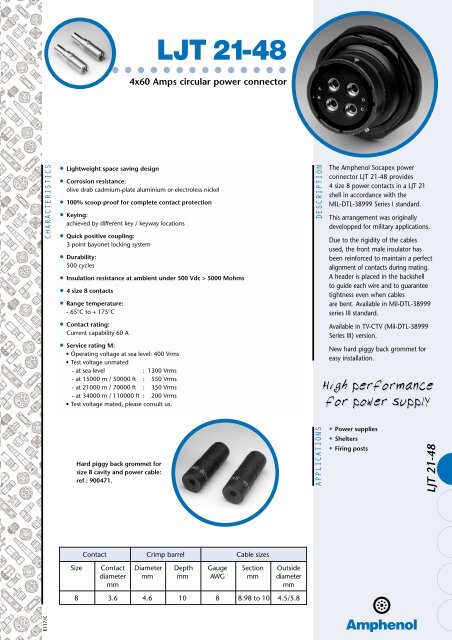
LJT <strong>21</strong>-<strong>48</strong>4x60 Amps circular pow<strong>er</strong> <strong>connector</strong>CHARACTERISTICS• Lightweight space saving design• Corrosion resistance:olive drab cadmium-plate aluminium or electroless nickel• 100% scoop-proof for complete contact protection• Keying:achieved by diff<strong>er</strong>ent key / keyway locations• Quick positive coupling:3 point bayonet locking system• Durability:500 cycles• Insulation resistance at ambient und<strong>er</strong> 500 Vdc > 5000 Mohms• 4 size 8 contacts• Range temp<strong>er</strong>ature:- 65°C to + 175°C• Contact rating:Current capability 60 A• S<strong>er</strong>vice rating M:• Op<strong>er</strong>ating voltage at sea level: 400 Vrms• Test voltage unmated- at sea level : 1300 Vrms- at 15000 m / 50000 ft : 550 Vrms- at <strong>21</strong>000 m / 70000 ft : 350 Vrms- at 34000 m / 110000 ft : 200 Vrms• Test voltage mated, please consult us.DESCRIPTIONThe Amphenol Socapex pow<strong>er</strong><strong>connector</strong> LJT <strong>21</strong>-<strong>48</strong> provides4 size 8 pow<strong>er</strong> contacts in a LJT <strong>21</strong>shell in accordance with theMIL-DTL-38999 S<strong>er</strong>ies I standard.This arrangement was originallydevelopped for military applications.Due to the rigidity of the cablesused, the front male insulator hasbeen reinforced to maintain a p<strong>er</strong>fectalignment of contacts during mating.A head<strong>er</strong> is placed in the backshellto guide each wire and to guaranteetightness even when cablesare bent. Available in Mil-DTL-38999s<strong>er</strong>ies III standard.Available in TV-CTV (Mil-DTL-38999S<strong>er</strong>ies III) v<strong>er</strong>sion.New hard piggy back grommet foreasy installation.High p<strong>er</strong>formancefor pow<strong>er</strong> supplyHard piggy back grommet forsize 8 cavity and pow<strong>er</strong> cable:ref.: 900471.APPLICATIONS• Pow<strong>er</strong> supplies• Shelt<strong>er</strong>s• Firing postsLJT <strong>21</strong>-<strong>48</strong>Contact Crimp barrel Cable sizesSize Contact Diamet<strong>er</strong> Depth Gauge Section Outsidediamet<strong>er</strong> mm mm AWG mm diamet<strong>er</strong>mmmm8 3.6 4.6 10 8 8.98 to 10 4.5/5.8E117/C
DIMENSIONAL CHARACTERISTICSDimensional charact<strong>er</strong>istics• Square flange receptacle• Jam nut receptacleA = 33.83 mmB = 15.29 mmC = 31.75 mmE = 39.67 mmF = 3.<strong>25</strong> mmG = 1.1875 - 18 2 A UNEFA = 33.83 mmB = 1.5000 - 18 UNEF inchesC = 43.00 mmE = 49.23 mmF = 52.65 mmG = 1.1875 - 18 2 A UNEFa = 8.33 mm Maxwithout protrusion of thepiggy back grommet.• PlugG = 1.1875 - 18 2 A UNEFC = 41.28 mma = 31 mm Maxwithout protrusion of thepiggy back grommet.• Position of major key wayA = 80° B = 69° C = 1<strong>21</strong>° D = 110°Receptacle: front face shown• Panel drilling for square flange and jam nut receptacleSquare flange receptaclefront panel mountingJam nut receptacleback panel mountingR4 Ø WØ EØ DFGV+0+0Shell R V-0.<strong>25</strong>W-0.<strong>25</strong>G E F-0.<strong>25</strong>DSize (mm) (mm) (mm) Mini Mini (mm) Mini(mm) (mm) (mm)<strong>21</strong> 31.75 42.5 3.<strong>25</strong> 50.60 38.28 37.06 32.16Panel thickness for jam nut receptacle : 1.6 mm mini3.2 mm maxi+0+0-0.<strong>25</strong>
Ins<strong>er</strong>t arrangement <strong>21</strong>-<strong>48</strong> particularities• Side half-view of female plug/receptacle• Side half-view of male plug/receptacle• Ins<strong>er</strong>t arrangement: front face shownMale plugLJT <strong>21</strong>-<strong>48</strong>INSERT ARRANGEMENT <strong>21</strong>-<strong>48</strong> PARTICULARITIESFemale receptacle
HOW TO ORDERConnectorsProprietary P/NS<strong>er</strong>iesShell type:00: square flange receptacle01: in-line receptacle07: jam nut receptacle06: plugLJT 00 RT <strong>21</strong> <strong>48</strong> P A 014Connector class:RT: for environmental applications (supplied withoutrear accessories).Design provides s<strong>er</strong>rations on rear threads of shells.<strong>21</strong>: shell size<strong>48</strong>: ins<strong>er</strong>t arrangement (4 size 8 contacts)Contact type:P: pinS: socketPolarization, rotation of major keyway:None = normalA, B, C, D.Shell finish :014: olive drab cadmium023: electroless nickel(Connector supplied with 4 contacts and 4 piggy back grommets 900471)For additional information, please see our LJT catalog.ContactsMale contact: 900198 Female contact: 900<strong>21</strong>7Reducing sleeve for AWG10: 900154 Piggy Back grommet: 900471Num<strong>er</strong>ous piggy back grommets are available depending to cable diamet<strong>er</strong>s. Please consult us.BackshellsThis <strong>connector</strong> is compatible with all backshells available for LJT <strong>connector</strong>s (MIL-DTL-38999 S<strong>er</strong>ies I / HE 308):LJT NSA = HE308-13 / LJT NSB / LJT NSD = HE308-14 / LJT SAD / LJT SACHE308-35 band backshell (BAND-IT System).ToolingCrimping pli<strong>er</strong>:Position<strong>er</strong>:809872809873Do not hesitate to contact us for furth<strong>er</strong> informationControlling gauge:Metallic removal tool:809877809845AmphenolAmphenol SocapexMil/A<strong>er</strong>o & Industrial Business Unit9<strong>48</strong>, Promenade de l’Arve - BP 29F - 74311 Thyez CedexTel.: +33 (0) 4 50 89 28 00 - Fax: +33 (0) 4 50 96 19 41http://www.amphenol.comSales office in ParisTel.: +33 (0) 1 49 05 30 00 - Fax: +33 (0) 1 49 05 30 43The information given in this document is as a guideline only. We res<strong>er</strong>ve the right to modify our products in any way we deem necessary. Any duplication is prohibited, unless approved in writing.E117/C
LJT <strong>25</strong>-<strong>1A</strong>4x100 ACircular pow<strong>er</strong> <strong>connector</strong>MAIN CHARACTERISTICS• 4 size 4 crimp contacts(male contact diamet<strong>er</strong>: 7.4 mm)• 4 size 16 crimp contacts(male contact diamet<strong>er</strong>: 1.6 mm)• Working temp<strong>er</strong>ature:- 54°C/+ 64°C whith a constant current of 100 A p<strong>er</strong> pow<strong>er</strong> contact• Temp<strong>er</strong>ature range:- 65°C/+ 175°C• Insulation resistance at ambient und<strong>er</strong> 500 Vdc > 5000 Mohms• Lightweight space saving design• Quick positive coupling:3 point bayonet lock system• 100% scoop-proof for total contact protection.• Keying:achieved by diff<strong>er</strong>ent key / keyway locations• Corrosion resistance:olive drab cadmium-plate aluminium• Durability:500 cycles• Contact rating:• Current capability- 100 A (size 4 contacts)- 13 A (size 16 contacts)• S<strong>er</strong>vice rating M:• Op<strong>er</strong>ating voltage at sea level : 400 Vrms• Test voltage unmated at sea level : 1300 Vrms- at 15000m / 50000 ft : 550 Vrms- at <strong>21</strong>000m / 70000 ft : 350 Vrms- at 34000 m / 110000 ft : 200 Vrms• Test voltage mated, please consult us.• Mating force:F < 4.6mN• Disconnection force :0,6mN < F < 4.6mN• Random vibrations at 0.4g2/Hz (50 to 2000 Hz in two directions):no electrical discontinuities > 1µsDESCRIPTIONAPPLICATIONSThis pow<strong>er</strong> <strong>connector</strong> fromAmphenol LJT <strong>25</strong>-<strong>1A</strong> wasoriginally developped for militaryapplications. Indeed, it is used inthe conditioning of tanks.This <strong>connector</strong> has the particularityto provide 4 size 4 pow<strong>er</strong> contactsand 4 size 16 contacts in a size<strong>25</strong> shell in accordance with theMIL-C-38999 S<strong>er</strong>ies 1 standard.High p<strong>er</strong>formancefor pow<strong>er</strong> supply• This <strong>connector</strong> is ideally suitedto harsh environment / military /a<strong>er</strong>onautic uses for pow<strong>er</strong> bus /loop and conditioned pow<strong>er</strong>supplies.E116/A4x100 A
CHARACTERISTICSApplication tools & process (coupled with backshell HE 308-35-<strong>25</strong>-30-36)For this pow<strong>er</strong> <strong>connector</strong>, we recommend the use of our backshell HE 308-35 for optimum p<strong>er</strong>formance.Tool ref<strong>er</strong>ences• For size 16 contacts:• Crimping pli<strong>er</strong>s• Turret position<strong>er</strong>(Position numb<strong>er</strong> 5)• Removal tool• For size 4 contacts• Crimping pli<strong>er</strong>s& a pair of jaws (One of the jaws isequipped with a positioning stop )• Removal tool (4 are needed)• For the rear accessories: 2 possibilities➊ ITS System• Pli<strong>er</strong>s• Tool• Tool❷ BAND-IT System• Tool80985780985880994<strong>48</strong>099478099<strong>48</strong>809943809949809950809951809952Installation instruction• Cable preparation• We recommend the use of the band backshell with aminimum chamb<strong>er</strong> diamet<strong>er</strong> of 30mm suitable for thesize of conductors.• First place the heat-shrink sleeve ov<strong>er</strong> the cablefollowed by the backshell HE308-35.• Stripping process• Cut the jacket from the cable taking care not todamage the braid.• Comb the braid back and stick it to the out<strong>er</strong> jacketwith adhesive.• Trim the size 4 conductors to 65mm ensuring th<strong>er</strong>e isno diff<strong>er</strong>ence in the lengths of these conductorsgreat<strong>er</strong> than 1mm. (This is to avoid damage to clips inthe insulator) (See figure 1).• Crimping process• Crimping of size 16 contacts (Locator positioned numb<strong>er</strong> 5)- The strip length of the size 16 conductors should be 6mm.- Crimp the contact of each size16 wire with the corresponding tool.- Aft<strong>er</strong> having crimped the size 16 contacts fold them back and position them with adhesive (see figure 2).• Crimping of size 4 contacts- The strip length of the size 4 conductors should be 13 mm.- Choose male or female positioning stop on your corresponding crimping tool.- Crimp the contacts.• Contact ins<strong>er</strong>tion• Check the position of each contact before ins<strong>er</strong>ting it in the cavity.• Ins<strong>er</strong>t firstly the 4 size 4 contacts in the insulator and push them until locked, and secondly do the same forsize 16 contacts.• Removal process• Take off the heat shrink sleeve and remove the band, fold back the braid and screw off the backshell.• Remove the size 16 contacts one by one using the tool 809944.• Fold back size 16 wires and secure them with adhesive.• Then remove secondly the 4 size 4 contacts at the same time, using 4 removal tools (see figure 3).Figure 180 ±0,515 ±0,5 Figure 2adhesive≈ 1 mmbraidadhesivesize 4 conductorsize 16 conductorsize 4 conductorFigure 34 removal tools30 minstraight
• 07 receptacleA = 40.18 mm B = 1.7500 - 18 UNEF inches C = 51.20 mmE = 55.58 mm F = 59.13 mm G = 1.4375 - 18 2A UNEFDIMENSIONAL CHARACTERISTICS• PlugG = 1.4375 - 18 2A UNEF C = 47.63mm a = 31 mm Max• Receptacle and plug mated• Position of major keywayA = 80° B = 69° C = 1<strong>21</strong>° D = 110°Receptacle: front face shown• Panel drilling detail for jam nut receptacleJ = 44.68 +0.<strong>25</strong> / -0 H= 43.41 +0 / -0.<strong>25</strong> K= 59.7 mm min4x100 A
HOW TO ORDERHE308 military P/NHE308 s<strong>er</strong>ies ReceptaclePlug07 for jam nut receptacle00 for square flange06 for plug07HE 308 T <strong>25</strong> 44 P 06SB7 MS<strong>er</strong>viceShell sizeContact arrangementContacts:P for pin (for receptacle only)S for socket (for plug only)Coding:B: position of major keywayN for standard or A, B, C, DShell finish:7: olive-drab cadmium platedIn accordance with DAT specificationProprietary P/NReceptacle07PLJT s<strong>er</strong>ies PlugLJT RT <strong>25</strong> <strong>1A</strong> B 01406S07 for jam nut receptacle00 for square flange01 for cable connecting receptacle06 for plugS<strong>er</strong>viceShell sizeContact arrangementContacts:P for pin (for receptacle only)S for socket (for plug only)Coding:B: position of major keywayNothing for standard or A, B, C, DShell finish:014: olive-drab cadmium platedBackshellsThe <strong>connector</strong> is compatible with all backshells available in our LJT range :LJT SAD HE 308-35 LJT NSA/HE30813LJT SAC LJT NSB LJT NSD/HE30814MÉDIASQUARE (33) 01 46 31 36 36Do not hesitate to contact us for furth<strong>er</strong> informationImmeuble le Doublon - 11, avenue Dubonnet92407 Courbevoie CedexTel. : (33) 1 49 05 30 00 - Fax : (33) 1 49 05 30 44<strong>Tec</strong>hnical supportTel. : (33) 4 50 89 28 00The information given in this document are as a guideline only.We res<strong>er</strong>ve the right to modify our products in any way we deem necessary.Any duplication is prohibited, unless approved in writing.E116/A
TV <strong>25</strong>-<strong>1A</strong>•••••••••••••••••Circular pow<strong>er</strong> <strong>connector</strong> 4 x 100 AMAIN CHARACTERISTICS• Lightweight space saving design• Corrosion resistanceolive drab cadmium-plate aluminium or electroless nickel• 100 % scoop-proof for total contact protection• Keyingachieved by diff<strong>er</strong>ent key / keyway locations• Durability500 cycles• Insulation resistance at ambient und<strong>er</strong> 500 Vdc > 5 000 MohmsDESCRIPTIONThe Amphenol Socapex pow<strong>er</strong><strong>connector</strong> TV <strong>25</strong>-<strong>1A</strong> provides 4size 4 pow<strong>er</strong> contacts + 4 size16 contacts in a TV <strong>25</strong> shell inaccordance with the MIL-DTL-38999 S<strong>er</strong>ies III standard.This arrangement was originallydeveloped for militaryapplications.Available in MIL-DTL-38999s<strong>er</strong>ies I standard and RNJ(cylindrical rack and panel).• 4 size 4 crimp contacts + 4 size 16 crimp contacts• Temp<strong>er</strong>ature range- 65 °C to + 175 °C• Contact ratingcurrent capability : - 100 A (size 4 contacts)- 13 A (size 16 contacts)• S<strong>er</strong>vice rating M- Op<strong>er</strong>ating voltage at sea level : 400 Vrms- Test voltage unmated : at sea level 1300 Vrmsat 15000 m / 50000 ft 550 Vrmsat <strong>21</strong>000 m / 70000 ft 350 Vrmsat 34000 m / 110000 ft 200 Vrms- Test voltage mated : please consult usHighp<strong>er</strong>formancefor pow<strong>er</strong>supplyAPPLICATIONS• Pow<strong>er</strong> supplies• Shelt<strong>er</strong>s• Firing posts• oth<strong>er</strong>sAmphenol
HOW TO ORDERCircular pow<strong>er</strong> <strong>connector</strong> 4 x 100 AProprietary P/NS<strong>er</strong>ies TV P00 RW <strong>25</strong> <strong>1A</strong> S A -Shell typeP00 : Square flange receptacle 175°C07 : Jam nut receptacle 175 °C06 : Straight plug 175 °CShell mat<strong>er</strong>ial, finish and contact typeRW : Aluminum, O.D. cadmium plated, crimp contactsShell size<strong>25</strong>Ins<strong>er</strong>t arrangement<strong>1A</strong> : 4 size 4 contacts + 4 size 16 contactsContact typeP : PinS : SocketPolarizationBlank for normal or A,B,C,D,EContactsBlank : Connector deliv<strong>er</strong>ed with contactsLC : Connector deliv<strong>er</strong>ed without contactIns<strong>er</strong>t arrangement : Male front face shownToolingFor size 4 contacts : Crimping pli<strong>er</strong> : 809947 Jaws : 8099<strong>48</strong> Removal tool : 809943 (4 are needed)For size 16 contacts : Crimping pli<strong>er</strong> : 809857 Turret : 809858 Removal tool : 809944Amphenol Socapex Promenade de l’Arve -B.P.29 - 74311 THYEZ - FRANCE - Tel. :33 (0) 4 50 89 28 00 - Fax : 33 (0) 4 50 96 19 41Copyright. Printed in France by Amphenol Socapex.