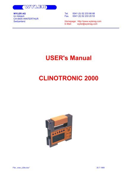
USER's Manual CLINOTRONIC 2000
USER's Manual CLINOTRONIC 2000
USER's Manual CLINOTRONIC 2000

You also want an ePaper? Increase the reach of your titles
YUMPU automatically turns print PDFs into web optimized ePapers that Google loves.
PPanel and display 2.11 7Possible configuration 1.3 6Power supply, external 6 33QQuick calibration 5.5.1 29RReference, resp. differential measurement with two CLINO <strong>2000</strong> 3.11 25REL zero offset 2.2.1 8Relative base length, measurement 3.3 16Relative measurement 3.5.2 22Relative measurement / absolute measurement 3.9 22Reset 3.1 11Resolution 6 33Reversal measurement 3.2.1 12SSelecting a sensor or an instrument 3.7 21Selecting correct filter type for various applications 3.8 21Selecting the measuring unit 3.3 16Selection pointer 2.2.2 10SEND/ESC key 2.2.1 8Sensor / instrument, selection 3.7 21Sensor / Port A-B 2.2.2 10Sensor address 2.2.2 10Sensor address changing 5.4 27Service 5. 27Service 5 27Settling time 6 33Shutting off the instrument 2.2.1 8Spare parts 5.3 27Spare parts 5.3 27Starting 1.2 5Starting / How to use the instrument 2. 7Storage 5.2 27Storage 5.2 27TTechnical data 6. 33Technical data 6 33Temperature range 6 33Terminating a measurement or a set up 3.6 21Terminating a measurement or a set up 3.6 21VVirtual zero, automatic set-up 3.2.2 14ZZERO absolute (with reversal measurement) 3.2 12Zero offset 2.2.1 8ZERO VIRTUAL 3.2 12ZERO VIRTUAL 3.2.2 13ZERO/SEL “+/-“ key 2.2.1 9ZERO-Setting / ZERO absolute and ZERO virtual 3.2 12ZEROTRONIC sensor 5.4 28Page 4 of 33
1. INTRODUCTION1.1. DESCRIPTION OF THE CLINO <strong>2000</strong>The CLINO <strong>2000</strong> was developed by WYLER AG as an intelligent display and measuring unit together with thedigital instrument’s family ZEROTRONIC. With this instruments all the sensors and instruments of theZEROTRONIC family can be used (See point 1.3 Configuration)The CLINO <strong>2000</strong> is a- Measuring instrument- Display unitOn the CLINO <strong>2000</strong> a number of parameters can be changed and adjusted:- Measuring unit- Measuring mode- Relative base length and many moreThe CLINO <strong>2000</strong> is compatible with the other instruments of the ZEROTRONIC family by using the RS485serial communication. The measuring values may be transmitted to a printer or a PC/Laptop via RS232 output.The measuring principle of the ZEROTRONIC family is based on a changing of the capacity of a condenserbuilt of two electrodes and a pendulum in form of a shield installed in between. The measured change ofcapacity is directly influenced by the change of the inclination of the pendulum. This capacity change is theprimarily used signal for the angle to be measured. The measuring system is designed to be completelyantimagnetic. The basic signal received in the CLINO <strong>2000</strong> will be computed into an angle by comparing thesignal with a reference curve stored and then displayed in the required unit.1.2. STARTINGBefore working with the CLINO <strong>2000</strong> it is strongly recommended to carefully read this manual first.This will avoid malfunctioning by making unsuitable manipulations like e.g. deleting the calibration data in thesensor head etc.Page 5 of 33
1.3. POSSIBLE CONFIGURATIONStand alone unitTwo units connected for remote display or differential mode / max. 15mCLINO <strong>2000</strong> connected with ZEROTRONIC Sensor / max. 15mCLINO <strong>2000</strong> connected to a PC / RS232Page 6 of 33
CLINO <strong>2000</strong> connected with a MINILEVEL or LEVELTRONIC „NT“ for differential modeAll the above configurations can be used. For specifications of the sensors and the instruments see therespective data sheets.2. STARTING / HOW TO USE THE INSTRUMENT2.1. DESCRIPTION OF PANEL FUNCTIONS2.1.1. PANEL AND DISPLAYPage 7 of 33
2.2. KEY FUNCTIONS2.2.1. DESCRIPTION OF THE INDIVIDUAL KEYSON/MODE - KeyFunction - 1 - Pressing the ON/MODE key starts the CLINO <strong>2000</strong>. When keeping the keypressed all the LCD elements are lighted. After releasing the key the instrumentswitches to the measuring mode and the calibration data of the internal sensor hasbeen collected. After a short period of time the actual angle will be displayed in thelast used measuring unit. In case of trouble an error message will be displayed.(See point 4)When pressing the ON/MODE key for more than 3 seconds the display startsflashing and the automatic shut off is disabled. In the standard mode theinstrument shut off after about 5 minutes. To turn off the instrument press theON/MODE key for more than 3 seconds until the display disappears.Exeption: In case the instrument is powered by an external power supply, theinstrument is never shutting off automatically.Function - 2 - The ON/MODE is also used for moving the selection pointer on the lowerdisplay area. By pressing this key the selection pointer moves from one position tothe next.Function - 3 - For shutting off the CLINO <strong>2000</strong>; the ON/MODE key needs to be pressed for3-4 seconds until the displayed figures disappear.Function - 4 -Used for „ZERO-Setting“ of saved (memory) values in the function „REL ZERO“.To set the memory in this function to ZERO press the ON/MODE key, thedisplayed values will become ZERO. This has to be confirmed by pressingENTERENTER – KeyThe keyfunction.ENTER is used to save an entered value or to accept a selectedSEND/ESC- KeyFunction - 1 - The key SEND is used for the transmission of a measuring value through theRS232 port or to send the value to a printer or another connected system. Throughthe same port the values may also be transmitted to a PC or Laptop for furthertreatment of the data.Function - 2 -Function - 3 -Also used for canceling any „HOLD“ function and return to the measuring mode.Canceling any task not yet finished.Page 8 of 33
ZERO/SELECT "+/-" - KeyThe key ZERO "+/-" can be used to change a number of possibleparameters like e.g.- Measuring units- Measuring units, respectively ports ( „A“ / „B“ / „A+B“ / „A B“ )- Changing of the measuring range- Changing of the instruments address- Set up the relative base length- Set up of the „Zero-Offset“- Set up of the „REL Zero-Offset“ etc.HOLD - KeyFunction - 1 -Function - 2 -With the HOLD key a measured value may „frozen“. This value will bedisplayed until by pressing the key SEND the CLINO <strong>2000</strong> will return to themeasuring mode.When using the mode REL ZERO and ZERO the actual measuring value canbe accepted by pressing the HOLD keyPage 9 of 33
2.2.2. DESCRIPTION OF THE PANELMaindisplayThe actual measuring values of an active sensor/instrument are displayed. By using themode „SENSOR“ other sensors or instruments connected at port B may be selected,differential measurement may be applied.Indicator ofinclinationdirectionThe pictograph indicates the direction of the inclinationdeclining to the right (negative angle)inclining to the right (positive angle)Selection pointerWith the selection pointer the intended function can be chosen:SENSORABSOLUTEREL ZEROUNITZEROLIMITSFILTERADDRESSCALIBONLINESelect the active sensor/portAbsolute measuring modeRelative measuring modeSelection of measuring unitsSet absolute zeroOutput of control signalsAdjustment of filter typeDisplay and changing of sensoraddressesCalibration of sensorsDisplay of active communicationthrough portBattery display"BATT"Measuring unitsWhen the battery power is low, the sign "BATT" is constantly onThe actual measuring unit is displayed. 10 basic units are availableand most of them can in addition be changed into subunits.Sensor/port A-B Function - 1 - The connection/port is displayed forinformation concerning:- the displayed measuring value- active sensor/instrument forcalibrationpurposesFunction - 2 -Shows the measuring mode e.g.individual measuring or differentialmeasuring (A-B)Sensor addressThe active sensor address is displayedPage 10 of 33
3. HOW TO USE THE CLINO <strong>2000</strong>3.1. CHECKING THE FUNCTIONSThe key ON/MODE can be pressed. As long as this key is pressed all elements of the LCD display will showup. After releasing the key the mode is switched to the measuring mode. The active signal is displayed in thelast used measuring unit. During the reading of the calibration data six small „o“ will be displayed.The following display variations are correct:When now the connected instrument or sensor is tilted, the displayed value must change accordingly.If a second instrument or an additional sensor has been connected to port B, a respective message may appearif some errors are noted:The following error messages are possible:ERROR 0 Instrument is defect, to be sent to the service centerERROR 1 No sensor or instrument connected, or not properly installedERROR 2 No measurement has been done so far with the connected sensor/instrument.The sensor must be addressed correctly (See point 3.7. Selecting a sensor oran instrument)ERROR 3 Calibration data not available. The display shows the malfunctioning item (portand address) also possible when the battery power is not sufficient(Communication with sensor not possible)For other error messages see point 4To reinstall the basic set up a RESET may be done at any time. The procedure is as follows:Both keys ON/MODE and ENTER must be pressed simultaneously for at least one second. All themanually installed data is lost and the CLINO <strong>2000</strong> will be set to the following basic standards:Basic standards:Measuring mode:absoluteMeasuring unit:the next possible and useful unitRelative Base:1000 mmZERO-OFFSET absolute:remains intactSensor: PORT A, no Sensor (ERROR 2)Filter No 5Immediately after RESET the error message 2 is displayed. This means the connected sensor must beaddressed correctly from new. (See point 3.7. Selecting a sensor or an instrument)Page 11 of 33
3.2. ZERO-SETTING / ZERO ABSOLUTE AND ZERO VIRTUALRemarks:Using ZERO SETTING two different tasks can be realized:a) ZERO ABSOLUTE / The instrument shows "0" when the angle of the mounting surface is exactlypositioned in the direction of the center of the earth.b) ZERO VIRTUAL / The instrument shows "0" at any predefined angle.3.2.1. ZERO ABSOLUTE (WITH REVERSAL MEASUREMENT)The ZERO absolute is the basis for all the inclination measurements in the absolute mode. For such ameasurement if high precision is required, it is of utmost importance that the object to be measured and theCLINO <strong>2000</strong> are both at the same temperature level. The CLINO <strong>2000</strong> should have been turned on a fewminutes before the measurement procedure. For this procedure a suitable surface must be chosen (rigid, flatand as horizontal as possible). On this surface the CLINO <strong>2000</strong> must be placed; the exact position of theinstrument is to be marked on the surface.The ZERO absolute will automatically be set by applying thereversal measurement. (Taking two measurements on thesame spot but in the 180° opposite direction) For this procedurea suitable surface must be chosen (rigid, flat and as horizontalas possible). On this surface the CLINO <strong>2000</strong> must be placed,the exact position of the instrument is to be marked on thesurface.The „ZERO-OFFSET“ is stored in the CLINO <strong>2000</strong>EXAMPLE:The selection pointer of the CLINO <strong>2000</strong> must now be placedbelow the marking ZERO by pressing the ON/MODE keyseveral times. If the required position is reached, it must beconfirmed by pressing ENTER. On the display the last set„Zero-Offset“ (Basic offset) will be displayed. The directionindicator (+/-) is flashing.The CLINO <strong>2000</strong> must now sit at position one and after a fewseconds settling time allowed, by pressing the key HOLD, thefirst reading is collected. This first value is displayed and theselection pointer below ZERO is flashing which means the secondreading is expected.The CLINO <strong>2000</strong> must now be rotated horizontally by 180° andplaced exactly on the same spot. After a few seconds settling timethe key HOLD must be pressed again for collecting thesecond reading.The computed „Zero-Offset“ (Basic offset) is now displayed onthe CLINO <strong>2000</strong>.(The displayed „Zero-Offset“ is calculated by adding the tworeadings and dividing the result by two.)Page 12 of 33
If this „Zero-Offset“ (Basic offset) must now be saved,the key ENTER must be pressed. Immediately afterthis, the selection pointer jumps to the measuring modeabsolute and the measuring result under considerationof the „Zero-Offset“ (Basic offset) will be displayed.The „Zero-Offset“ (Basic offset) computed by applying the reversal method is the deviation of the instrument’sZERO to the absolute ZERO. The display on the CLINO <strong>2000</strong> therefore is the:Displayed value =Value of the CLINO <strong>2000</strong> minus „Zero-Offset“.The reversal measurement to establish the exact „Zero-Offset“ (Basic offset) should be done periodically if highquality measurements are required. Especially after longer intervals the method is useful.3.2.2. ZERO VIRTUALI) <strong>Manual</strong> set-up of the virtual ZEROOne possibility of using ZERO virtual means to establish an artificial plane, respectively angle, to be chosen asabsolute zero.Another possibility is to change the existing „Zero-Offset“ (Basic offset) of the CLINO <strong>2000</strong> e.g. established bymeans of using the reversal method.Example:Only well skilled and trained user should make use of this feature!!!Initial position:The display on the CLINO <strong>2000</strong>shows the measured value of+0°07‘20‘‘. This value is the trueinclination of the instrument.Only one sensor (internal sensor of the CLINO <strong>2000</strong> or the external sensor connected to Port “B”) at a time canbe set to ZERO virtual. This sensor must be selected first.The selection pointer must be moved below the marking ZERO in the display of the CLINO <strong>2000</strong> by pressingthe key ON/MODE several times. If reached the selection must be confirmed by pressing ENTER.The last computed or manually entered value „Zero-Offset“(Basic offset) is displayed. In our example 00° 00‘ 00‘‘The direction indicator is flashingThis displayed value may now be changed manually byapplying the keys ZERO/SELECT „+/-“ to the desiredvalue.e.g. from +0° 00’ 00’’ to new +0°07‘20‘‘The direction indicator is flashingThe value is now the new „Zero-Offset“Page 13 of 33
If this so manually established „Zero-Offset“ must now besaved the key ENTER must be pressed. The new „Zero-Offset“ is now saved in the CLINO <strong>2000</strong>. Immediately after this,the selection pointer jumps to the measuring mode absoluteand the measuring result under consideration of the new„Zero-Offset“ will be displayed. The following new value willnow be displayed in the absolute mode:„ZERO-OFFSET“ is stored in the CLINO <strong>2000</strong>Displayed value =Value of the CLINO <strong>2000</strong> minus „Zero-Offset“.Remarks: Until the input is confirmed by using the ENTER key, every manipulation can bestopped any time by pressing SEND/ESCResult:Despite the fact that CLINO <strong>2000</strong> isstill placed at the same angle thedisplay of the instrument now showsthe value 0°00‘00‘‘ This is the socalled virtual ZEROThis new virtual ZERO is thereference for all the futuremeasurements based on this angle(originally 0°07‘20‘‘)II) Automatic set-up of the virtual ZEROPractically quite often a measuring surface is not absolutely horizontal but should be the reference plane forother measurements. In these cases it is useful to set the basic value for this surface to: 0°00’00‘‘This can be done by manually setting the virtual zero as described before or by automatically define the valuewith the CLINO <strong>2000</strong> set-up. (It is done by using a reversal measurement mode without turning the instrument180 deg.)Procedure:Initial position:The display shows the measuredvalue on the CLINO <strong>2000</strong> :+0°09‘16‘‘. This value is the trueinclination of the CLINO <strong>2000</strong>.The selection pointer must be moved below the marking ZERO in thedisplay of the CLINO <strong>2000</strong> by pressing the key ON/MODE severaltimes. If reached the selection must be confirmed by pressingENTER.The last computed or manually entered value „Zero-Offset“. Thedirection indicator is flashingPage 14 of 33
The CLINO <strong>2000</strong> must now sit at position one and after a fewseconds settling time allowed, by pressing the key HOLD,the first reading is collected. This first value is displayed and theselection pointer below ZERO is flashing which means thesecond reading is expected.After a few seconds settling time the key HOLD must be pressed again for collecting the second reading.The instrument remains at the same position without turning 180°.The newly computed „Zero-Offset“ is now displayed on theCLINO <strong>2000</strong>(The displayed „Zero-Offset“ is calculated by adding the tworeadings and dividing the result by two.)If this „Zero-Offset“ must now be saved, the key ENTER mustbe pressed. Immediately after this, the selection pointer jumps tothe measuring mode absolute and the measuring result underconsideration of the „Zero-Offset“ (Basic offset) will bedisplayed.The „ZERO-OFFSET“ is stored in the CLINO <strong>2000</strong>Displayed value =Value of the CLINO <strong>2000</strong> minus „Zero-Offset“.Remarks: Until the input is confirmed by using the ENTER key, every manipulation can be stopped at anytime by pressing SEND/ESCResult:Despite the fact that theCLINO <strong>2000</strong> is still placed at thesame angle the display of theinstrument now shows the value0°00‘00‘‘ This is the so calledvirtual ZEROThis new virtual ZERO is thereference for all the futuremeasurements based on this angle(originally 0°09‘16‘‘)Remarks: Please see also "Relative measurement" Chapter 3.9.2Page 15 of 33
3.3. SELECTION OF THE MEASURING UNITThe desired measuring unit can be selected by repeatedly pressing the key ON/MODE until the selectionpointer is below the function UNIT and then the ENTER is pressed.The possible formats may now be chosen by pressing the key ZERO/SELECT "+/-" until the desired unitis displayed. This selection must be confirmed by pressing ENTER. The selection remains valid untilchanged in the same manner as described above.The following measuring units can be chosen:xxx° xx' DEG Deg / Minxx° xx' xx" DEG Deg / Min / Secxxxx' xx" DEG Min / Secxxx.xxx° DEG Degree, 3 decimalxxx.xx %o ‰, 2 decimalxxx.xx A %o Artillerie-Promillexx.xxxx "/REL mm per relative base, 4 decimalxxx.xx mm/REL mm per relative base, 2 decimalxxxx.xx mRad Milliradian, 2 decimalxx.xxxx "/12" Inch per 12 Inch, 4 decimalxx.xxxx "/10" Inch per 10 Inch, 4 decimalxxxx.xx mm/m mm per m, 2 decimalxxx.xxx GON New degree, 3 decimalFor a measurement with relative base length the selectionpointer must be moved by repeatedly pressing the ON/MODEkey to the position UNIT. Confirm with ENTER.By using the keys ZERO/SELECT "+/-" the desired unitcan now be chosen (mm/REL or inch/REL) The selection must beconfirmed with the key ENTER.On the display the direction indicator is flashing alternatively plusor minus; the existing base length is shown (Standard length is1000 mm or 10")By pressing ENTER this value may be accepted or withZERO/SELECT „+/-“ the relative base length may beadjusted as required and then finally confirmed withENTER.In the relative mode the angle is related to the height "X" as theelevation over the set relative base length in the chosenunit (in mm, or Inch).Exception: RESET (see point 3.1)Page 16 of 33
3.4. HOLD-FUNCTIONThis function is available in all measuring modes.Place the CLINO <strong>2000</strong> on a flat stable surface. Use the keyHOLD. While the CLINO <strong>2000</strong> waits for a validmeasurement (two identical values in succession) the displaywill show "oooooo". As it is practically impossible for twosuccessive values to be identical while the instrument ishandled, the instrument may be positioned after the key isdepressed.As soon as the condition for a valid measurement is fulfilled,the measuring value is displayed, the direction indicatorflashing. To read the measurement value, the CLINO <strong>2000</strong>may be removed from its located position. The display value is"frozen".Use the key SEND/ESC. If a printer is connected, themeasured value will be transmitted and the CLINO <strong>2000</strong> will beready for use in the normal mode If you just want to read thevalue,pressing SEND/ESC again will return to the standard mode.If HOLD is required for the next measurement, it is possiblewithout canceling; directly to recall HOLD again.Remarks:The level of vibration at the measuring location considerably influences the time necessary tocollect a valid measurement. Severe vibration may even completely prevent the condition (twoidentical values in succession), necessary to register a true measurement.In order to regain measuring capability under this condition, take the instrument to an object witha lower vibration level and complete the operation in process. By key using SEND/ESC thefurther procedure may be cancelled immediately. The displayed value may now be accepted orthe process must be repeated.If after 60 seconds no value was accepted, the „ERROR 7“ message is displayed.HOLD function has not been successfully completed within 60 seconds. The procedureneeds to be repeated.By using the function RESET the CLINO <strong>2000</strong> will return to the standard settings. With theexception of the calibration data all previous adjustments are lost!!Page 17 of 33
3.5. FUNCTION SEND (PRINT-FUNCTION)Using the key SEND/ESC will send the displayed value through the port "RS 232" to a connected PC, orLaptop via the RS232 port. This function can also be used in combination with HOLD in order to transmit the„frozen“ value.The function SEND may be activated from a connected PC/Laptop by transmitting a letter „P“ (as letter) throughthe serial port RS 232DATA FORMAT OUT-PORTMeasurement activeMessMode_AMessMode_BMessMode_A_minusBMessMode_A_B[sss Aaaa sn.nnnnnn][sss Baaa sn.nnnnnn][sss Aaaa-Baaa sn.nnnnnn][sss Aaaa sn.nnnnnn Baaa sn.nnnnnn]sss = 0 .. 255 - Continuous no.aaa = Sensor Address 1..255 (e.g. 004) / ML/LT NT 1-32sn.nnnnnn = +9.999999 - Positive Overrange-9.999999 - Negative Overrangeother value - Angle in rad e.g. +0.226349Menue aktive or error ( -0.000000 means no data available)MessMode_AMessMode_BMessMode_A_minusBMessMode_A_B[9xy Aaaa -0.000000][9xy Baaa -0.000000][9xy Aaaa-Baaa -0.000000][9xy Aaaa -0.000000 Baaa -0.000000]aaa = Sensor Address 1..255 resp. 0 when address undefinedx = 0 - General error1 - Port A error2 - Port B errory = 0 - Menu active (no error)>0 - Error codes (According to manual)Format of transmissionasynchrony, 7Bit, 2 Stopbits, no parityPage 18 of 33
Example using the Hyper Terminal of Windows NT or Windows Terminal program(Example is WIN NT)1. Open the Terminal-Program inWindows / Accessories. and insert anameConfirm with OK2. Enter the serial port definitionconnected to the CLINO <strong>2000</strong>.Confirm with OK3. Enter the parametersBits per Second: 9600Data bits: 7Parity:noStop bits: 2Protocol:noConfirm with OKThe HyperTerminal-Windowsappear.Repeatedly pressing the keySEND/ESC the actual value willbe transmitted in [Rad]Alternatively the value can be calledby pressing the key "P" on the PCkeyboard.Page 19 of 33
CLINO <strong>2000</strong> with address 50 connected to port "A"Meaning of thedisplay:068Continuous number.(3 measurements persecond are performed)A050Port „A“, address 50-0.000100- 0.000100 Radresp.-100 µRadCLINO <strong>2000</strong> with address 50 is connected to port "A",one external sensor with address 21 is connected to port "B" / Measuring mode: A & B alternativelymeasuredMeaning of thedisplay:031A050Continuous number.Port „A“, address 50-0.000104B021+0.001079- 0.000104 Radresp.-104 µRadPort „B“address 21+0.001079 Radresp.+1079 µRadCLINO <strong>2000</strong> with address 50 is connected to port "A",one external sensor with address 21 is connected to port "B" / Measuring mode: A - B differentialmeasurementMeaning of thedisplay:141A050 – B021-0.001144Continuous numberMeasuring modeDifferential modePort „A“ CLINO <strong>2000</strong>with address 50 minusPort „B“ sensor withaddress 21DifferenceSensor [A] – [B]:- 0.001144 Radresp.-1144 µRadPage 20 of 33
3.6. TERMINATING A MEASUREMENT OR A SET UPIn case of the required canceling of a measuring procedure or the changing of parameters the process may beended at any time and the previous state will be installed by pressing SEND/ESC. This is true only as longas no change has been accepted by pressing ENTER before.3.7. SELECTING A SENSOR OR AN INSTRUMENTWith the CLINO <strong>2000</strong> the possibility exists to display the measured values of the instrument itself as well as thedifference between the instrument and an additional instrument or a connected sensor ZEROTRONIC. In caseof the differential measurement the second instrument must be connected to the port B (External sensor B). It isnot possible to measure the difference of two sensors connected to the same port.Basically the following set-up is possible:- Measurement of the CLINO <strong>2000</strong> (= internal sensor A, corresponding to Sensor/Port A)- Measurement of one or more instruments connected to port B- Differential measurement between the CLINO <strong>2000</strong> and another instrument at port B- Alternating display of the CLINO <strong>2000</strong> and an instrument connected to port BFor differential measurement respectively measurementwith a reference <strong>CLINOTRONIC</strong> <strong>2000</strong> see chapter”3.11. Differential- respect. Reference Measurement with two <strong>CLINOTRONIC</strong> <strong>2000</strong>”For choosing the measuring mode and the address of thesensors connected the ON/MODE key must be pressedrepeatedly until the selection pointer is below SENSOR andaccepted by pressing ENTER. The possibilities "Port A","Port B", "Port A-B" or "Port A B" may be selected byapplying the key ZERO/SELECT "+/-" The desiredselection can be accepted by pressing ENTER. After thisthe CLINO <strong>2000</strong> is looking for all the connected sensorsrespectively their address. Up to 255 sensors may beconnected. The address of the first sensor will be displayedflashing. During the searching procedure the frame of the„Sensor address“ will flash in circular motion below theselected port.If more than one sensor is connected to the port B, the onedesired can be selected by pressing ZERO/SELECTand confirmed with ENTER.In case of differential measurement between two sensors thesame procedure must be repeated for port B.After pressingENTER the respective measurement starts.3.8. SELECTING CORRECT FILTER TYPE FOR VARIOUS APPLICATIONSA number of different types of filters are incorporated. The standard factory setting is filter type no 5. To changethis setting the selection pointer must be moved below „Filter“. After pressing ENTER the actual setting isdisplayed. The number may be changed from 1 to 10 by using the + or - arrows and then be confirmed bypressing ENTER.The most suitable type of filter is best found out by practically testing, as the measuring conditions have quite aninfluence. Generally spoken it can be said that the lowest figure (almost no filter) sends the collected signalsrapidly to the display possibly resulting in an unstable display. The maximum filter (No. 10) mathematicallytreats the signal by collecting data and sending somewhat delayed a signal integrated over a period of time.Page 21 of 33
3.9. ABSOLUTE MEASUREMENT / RELATIVE MEASUREMENT3.9.1. ABSOLUTE MEASUREMENTThe standard mode (by default) is the absolute measurement.If this is not the case when starting the CLINO <strong>2000</strong> the ON/MODE key must be pressed repeatedly until theselection pointer is in position ABSOLUTE. This must be confirmed with ENTER and the absolute mode isready.The displayed value is theValue of the CLINO <strong>2000</strong> minus „ZERO - OFFSET“3.9.2. RELATIVE MEASUREMENTImportant remark:The defined „REL ZERO OFFSET“ is superimposed on the „ZERO-OFFSET“ stored in the CLINO <strong>2000</strong>.The „REL ZERO OFFSET“ stored temporarily in the CLINO <strong>2000</strong> can be recalled with any time when thesame instrument is connected. This value must be confirmed or changed for example to zero.In case of differential measurement ( 1 Sensor or instrument connected to Port A an port B each) the„REL ZERO OFFSET“ will be stored in the CLINO <strong>2000</strong>.Displayed value =Value of the instrument minus „ZERO-OFFSET“ minus „REL ZERO OFFSET“Initial position:The display shows the measured valueon the CLINO <strong>2000</strong> : +0°10‘00‘‘. Thisvalue is the true inclination of theinstrument.The requirement is now to set theinstrument's inclination at an angle ofzero and use this angle as a referencefor future measurements.Page 22 of 33
The selection pointer must be moved below the markingREL ZERO in the display of the CLINO <strong>2000</strong> by pressing thekey ON/MODE several times. If reached the selection mustbe confirmed by pressing ENTER.The last computed or manually entered value „REL ZEROvalue“, in our example 0° 00'‘00'‘ The direction indicator isflashingThe CLINO <strong>2000</strong> must now be at the correct position and after afew seconds settling time allowed, by pressing the keyHOLD, the reading is collected. This value )"REL ZEROOFFSET") is displayed.Should this value no be stored press ENTER. This relativezero value is stored in the CLINO <strong>2000</strong>. The display jumps intothe measuring mode "REL ZERO", the display is 0°00‘00‘‘ andthe measurement continues by considering the "REL ZEROOFFSET"As an alternative the value can also be changed manually byusing the key ZERO/SELECT "+/-" before confirmingwith ENTERResult:Despite the fact that the CLINO <strong>2000</strong>is still placed at the same angle thedisplay now shows the value0°00‘00‘‘ (Fig. 1)This new relative zero is thereference for all the futuremeasurements based on this angle(originally 0°10‘00‘‘)The selection pointer of the CLINO<strong>2000</strong> can now be placed below themarking ABSOLUTE by pressing theON/MODE key several times toreturn to the absolute measuringmode. After confirming withENTER the original value isdisplayed. (Fig. 2)Fig. 1Fig. 2The values stored in the stacks of „ZERO“ and „Relative Zero“ can be deleted as follows:Press the ON/MODE key repeatedly until the selection pointer is located under "REL ZERO"or "ZERO" and confirm with ENTER. In the display the existing value is seen. By using the keyZERO/SELECT "+/-" the value can be set to "0". This can now be confirmed withENTER and the CLINO <strong>2000</strong> starts in the measuring mode. The stack is empty.Page 23 of 33
3.10. MEASURING BY SETTING LIMITSWhen your task requires the indication of a surpassed measuring value with an "alarm" the LIMITS functionmust be used.In this mode it is possible to define an upper and a lower measuring limitation (LIMITS). After installation ofthe limits a signal will be seen on the screen and also sent through the port RS 232 if the measured value risesabove the upper limit or falls below the lower limit.For the setting of limits the selection pointer must be moved to the positionLIMITS by repeatedly pressing the key ON/MODE. If reached it needsto be accepted by pressing ENTER. In the display of the CLINO <strong>2000</strong>a possible installed lower limit is displayed with a marking LO. This valuemay now manually be adjusted to the required value by usingZERO/SELECT „+/-“. If reached it must be accepted by pressingENTER. After this the upper value is displayed with the marking HI.This value may now manually be adjusted to the required value by usingZERO/SELECT „+/-“. If reached it must be accepted by pressingENTER.ATTENTION: The upper limit (HI) must always, absolutely seen, behigher than the lower limit (LOW)After the confirmation in the display the upper limit is seen (remark HI)This value can be changed manually by using the keysZERO/SELECT „+/-“ and after confirming with ENTERthe limit is set.After the saving of the upper limit the display shows OFF or ON. By usingthe key ON/MODE the display jumps between the two possibilities.The desired mode must be confirmed with ENTER. (Means: limits ON or limits OFF) If the limits must not bestored, the procedure can be cancelled by using SEND/ESCIf during a measurement the limitsare reached the display startsflashing, alternatively the measuredvalue and the remark HI or LOdepending on the limit reached areseen.At the same time two signal will be transmitted to the port RS 232. The first signal may be used for an externalcontrol action or a relay (12V/500 mA) may be activated.The second signal transmits the polarity of the signal in relation to the set limitation.Page 24 of 33
3.11. DIFFERENTIAL-, RESPECT REFERENCE MEASUREMENT WITH TWO<strong>CLINOTRONIC</strong> <strong>2000</strong>Applying differential measurement respectively reference measurement means by definition using twoinstruments, a Measuring Instrument (A) and a Reference Instrument (B), whereas the difference betweenthe two angles is of interest (A-B). This difference remains unchanged when the same angular change isapplied on both instruments. This measurement is a special form of a relative measurement.The differential measurement has the greatest advantages in the following tasks:Measurements made on objects under influence of vibrationMeasurements made on objects and systems not rigid enough (unstable, flimsy)Measuring Instrument (A)Reference Instrument (B)Preconditions:• Both instruments are powered by either internal batteries in each instrument or by using an externalpower supply connected to one of the two instrument’s free socket “RS232”• Both instruments are connected together using the ports “EXTERNAL SENSOR (B)”, with abus cable (max. 1000 m)Start-upBoth instruments are placed in position and properlyconnected and power supply installed as mentionedabove.First the Reference instrument must be started bypressing the button ON/MODE.The ON/MODE key must now be pressedrepeatedly until the selection pointer is below ONLINEand accepted by pressing ENTER. The displayshows now “REF” what means that the instrument is inthe reference mode.Page 25 of 33
Secondly the Measuring instrument must bestarted by pressing the button ON/MODE.The ON/MODE key must now be pressedrepeatedly until the selection pointer is belowSENSOR and confirmed by pressing ENTER.The "Port A-B" must be selected for choosingdifferential mode, applying the keyZERO/SELECT "+/-" until the desiredselection is displayed, then accept by pressingENTER. After this the CLINO <strong>2000</strong> is lookingfor all the connected sensors respectively theiraddress. The correct addresses of (A) and (B)must be confirmed with ENTER.Remarks:When the differential mode is selected for thefirst time with the two respective instruments allthe calibration data must be collected andcomputed, this task will usually take up to twominutes time. After this the start-up time will beusually be reduced to approximately 20 to 30seconds.On the display of the measuring instrument themeasuring result (value of measuring instrumentminus value of reference instrument, A-B) is nowseen.As long as the installed configuration remains thesame only the ON/MODE key must bepressed on the two instruments for a renewedstart-up.Page 26 of 33
4. ERROR MESSAGESERROR 0ERROR 1ERROR 2Instrument’s fault, needs to be sent to the service centerSensor(s) /Instrument(s) not connected, or not correct addressNo measuring has been made with the connected sensor. The sensormust be addressed first (See point 3.7. Selecting a sensor or aninstrument)ERROR 3 No calibration data available (the respective sensor/port is displayed)ERROR 4 No sensor address foundERROR 5 More than one sensor foundERROR 6 Changing of sensor address was not successfulERROR 7 HOLD function has not been successfully completed within 60seconds. The procedure needs to be repeated.ERROR 8 Battery not correctly installedERROR 9 It was not possible to save the calibration data successfully in thesensor headRemarks:After the error message is displayed and confirmed withjumps to the position SENSOR (select sensor)ENTER the position indicator5. SERVICE5.1. GENERALThe CLINO <strong>2000</strong> needs no special service other than the regular cleaning.5.2. STORAGEThe CLINO <strong>2000</strong> should be stored in a save place, best in the transportation case. For longer storage periods itis recommended to remove the batteries.5.3. SPARE PARTSThe following spares are available:- Batteries- Cables5.4. CHANGING OF SENSOR ADDRESSMove the position indicator to the position ADDRESS byrepeatedly pressing the key ON/MODE and confirm thesetting with ENTER. If only one sensor is connected asdescribed above the respective port and address number isdisplayed flashing.Remarks:If more than one sensor is connected, the error message ERROR 5 is displayed. (More than one sensor found)Using the keys ZERO/SELECT the new address canbe entered and confirmed by pressing ENTER. If theprocedure was successful the measurement starts with thenewly given address.Page 27 of 33
Addresses of external Zerotronic sensors may be chosen between no. 1 and no. 254Addresses of external Measuring instruments (Minilevel NT, Leveltronic NT) may only be chosenbetween no. 1 and no. 32The address no 255 is reserved for service purposes and should not be used.The address of the internal sensor of the CLINO <strong>2000</strong> can’t be changed.The following error messages are possible:ERROR 4ERROR 5ERROR 6No sensor address foundMore than one sensor foundChanging of sensor address was not successfulPage 28 of 33
5.5 CALIBRATION5.5.1 QUICK CALIBRATIONThe CLINO <strong>2000</strong> is equipped with an integrated calibration set-up for a quick calibration procedure.On the backside of the instrument a number of precisely manufactured and placed holes are available forinstalling the dowel pins as calibration aids. These pins are part of the delivery and can be inserted into theholes. With the quick calibration method the values at + and - 45° as well as the exact zero value can be fixed.By this procedure the instrument can be set to a sufficiently high precision for most of the applications.The calibration procedure is as follows:1. Start the instrument in the mode „Absolute“ Point 3.9.12. Select menu „ZERO“ and confirm with ENTER Press ON/MODE several times untilthe selection pointer is below ZERO3. Press „MODE“ shortly (less than 5 sec.)4. Adjustment of angle at +45°,Pre-set value will be displayedThe dowel pins are to be inserted in such a way that theinstrument would display +45° when two pins are on ahorizontal plane.E.g. hold the instrument on the side of a measuring andsetting plate, the pins on top.Press HOLD, keep the instrument stableFirst displayed is oooooo, then the measured value isseen.Confirm with ENTER5. Adjustment of angle at 0°,Pre-set value will be displayedThe dowel pins are to be inserted in such a way that theinstrument would display 0° when two pins are on ahorizontal plane.E.g. hold the instrument on the side of a measuring andsetting plate, the pins on top.Press HOLD, keep the instrument stableFirst displayed is oooooo, then the measured value isseen.Confirm with ENTER6.Adjustment of angle at -45°,Pre-set value will be displayedThe dowel pins are to be inserted in such a way that theinstrument would display -45° when two pins are on ahorizontal plane.E.g. hold the instrument on the side of a measuring andsetting plate, the pins on top.Press HOLD, keep the instrument stableFirst displayed is oooooo, then the measured value isseen.Confirm with ENTER7. During the sampling of the collected values firstdisplayedis: . . . . . ., then oooooo, at the end it will automaticallyswitch in the measuring mode8. By applying a reversal measurement set the instrumentto absolute zero (see point 3.2.1)9. The CLINO <strong>2000</strong> is now calibrated and can be used formeasuring.The calibration aids (dowel pins) must be stored grease applied and any damage is to be prevented.Also the holes in the instrument must remain free of dust and dirt.Page 29 of 33
5.5.2 FINE CALIBRATION OVER THE WHOLE MEASURING RANGEThe fine calibration may be required when- the existing calibration was lost- the accuracy is not sufficient anymore- a connected sensor or the measuring range has changedFor such a calibration procedure a precise sine bar or an accurate index table should be available.Remarks:In order to guarantee the precise functioning of the instrument a minimum of seven calibrationpoints are required over the whole measuring range.Principle of the calibration methodThe bases of all the measurements with digital technology like the CLINO <strong>2000</strong> and the connectedsensors/instruments are the calibration data stored in the sensor heads. Throughout the whole measuring rangea number of reference calibrating points are stored in the sensor heads. The linearity of the measuring rangedepends on the number of these reference-calibrating points. Each measured angle delivers a signal in form ofa frequency and to these reference frequencies the respective calibration points are matched. From thesevalues a calibration curve will be established.The measured angles between these calibration points are computed by interpolation and displayed on thescreen in the desired measuring unit.All sensors/instruments leaving the factory at WYLER’s are calibrated according the measuring range and haveundergone a severe quality test procedure.Page 30 of 33
For the calibration procedure the selection pointer must be moved to the position CALIB by repeatedly pressingthe key ON/MODE. If reached it needs to be accepted by pressing ENTER. By using thekey ZERO/SELECT „+/-“ the respective port may be chosen. „Port A“, for the internal sensor in theCLINO <strong>2000</strong>, „Port B“ for a possible external sensor. The selected possibility must be confirmed bypressing ENTER.After this the CLINO <strong>2000</strong> is looking for all the connected sensors respectively their address. The address of thesensor will be displayed flashing. During the searching procedure the frame of the „Sensor address“ will flashin circular motion below the selected port.Are several sensors connected the required one must be selected by the keyconfirmed with ENTER.ZERO/SELECT „+/-“ andImmediately after this the calibration procedure is starting.In the display the last entered distance between two calibration points is seen. By using thekey ZERO/SELECT „+/-“ this distance may be entered from new. Two basic possibilities are available:I) Choose calibration point distance is between 0.5 and 7.5 degrees,in steps of 0.5 degrees.II) Choose calibration point distance is between 1.0 and 15.0 mm/m,in steps of 1.0 mm/m.For calibrating the CLINO <strong>2000</strong> it is recommended to use 5° 7.5° steps.After choosing the distance and confirming withENTER the procedure continuous as follows:- In the area of the sensor address the number of calibrating points isdisplayed (incl. zero position)- In the major display area the total calibration range to be calibrated isseen (Result of number of calibration points and the distances chosen).By applying ZERO/SELECT „+/-“ the number of calibration points may be changed. The correspondingcalibration range will automatically adjust. Confirm with ENTER.In the display the first angle to set is seen flashing. In the window „Address Sensor“ the number 1 is seen forthe first calibration point to be set.The CLINO <strong>2000</strong> or the external sensor must now be set to the first calibrating position on a suitable calibrationgauge (rotary table, sine bar). This angle is displayed flashing on the screen and the figure 1 is seen whichstands for the first calibration point.Page 31 of 33
If the correct position is installed and a few seconds settling time were allowed the value can be saved bypressing ENTER. During the reading of the data the display remains stable. After successful reading thenext calibration point will be displayed and the respective procedure must continue.Example Measuring range of CLINO <strong>2000</strong> +/- 45 degreesDistance between the calibrating points5.000 degreeNumber of calibrating points 23Range of calibration+/- 50 degreesResult 1. Calibration point - 55.000°2. Calibration point - 50.000°3. Calibration point - 45.000°……………………21. Calibration point + 55.000°After entering the last calibration point the complete calibration data will be saved in the sensor head. Duringthis procedure a moving bar is displayed and when successful finished the CLINO <strong>2000</strong> switches to themeasuring mode.If something went wrong the following message shows up:ERROR 9It was not possible to save the calibration data successfully in the sensorheadRemarks:The „ZERO-OFFSET“ and the „REL ZERO OFFSET“ will be set to zero.Until the definitive saving of the calibration values the procedure may bestopped by using ESC.Page 32 of 33
6. TECHNICAL DATAMeasuring range/MessbereichCalibration /KalibrierungSettling time /MesszeitResolution /AuflösungLimits of error /FehlergrenzeOptional:Built-in software andcalibration aidsInterne Kalibriersoftware undmitgelieferte KalibrierhilfenValue available after /Anzeige nachDepending on units setAbhängig von ausgewählterMasseinheit± 45 Arc.deg.± 10 Arc.deg.± 30 Arc.deg± 60 Arc.deg.23 Setting points /23 Kalibrierpunkte< 5 sec.5 Sec. of arc (≈ 0.025 mm/m)< 5 Sec. of arc + 0.07%R.O.Data connection /AnschlussPower supply withbatteries (Lifetime)After quick calibration, usingthe calibration aidsNach Kurzkalibrierung mit denKalibrierhilfenSpecial cables /SpezialkabelBatteries:< 30 Sec. of arcRS 485, asynchr., 7 Bit,2 Stopbits,no parity, 9600 Baud2 x Size AA 1.5V Alkaline(40 - 60 hrs)Stromversorgung mitBatterien (Betriebsdauer)External power supply /Externe SpeisungHousing (Weight) /Gehäuse (Gewicht)Temp. range /Temp. -BereichRemarks/Bemerkungen:Option, rechargeable batteries:Stainless steel /Stahl rostfreiOperating /BetriebstemperaturStorage /LagertemperaturF.S.=Full Scale; R.O.=Read Out;2 x Size AF 1,2 V NiMHrechargeable(30-50 hrs)+12... +48 V DC /200 - 500 mW150 x 150 x 35 mm (3 kg)0° to 40 °C.-20° to 70 °C.Remarks:The instruments are delivered with batteries of AA type. When using the type AF, the installedspacer is to be removed.When using external power supply the batteries may remain in the instrument.Rechargeable batteries must be charged outside of the instrumentPage 33 of 33