Anchorage Connector Instructions - Flexible Lifeline Systems
Anchorage Connector Instructions - Flexible Lifeline Systems
Anchorage Connector Instructions - Flexible Lifeline Systems

Create successful ePaper yourself
Turn your PDF publications into a flip-book with our unique Google optimized e-Paper software.
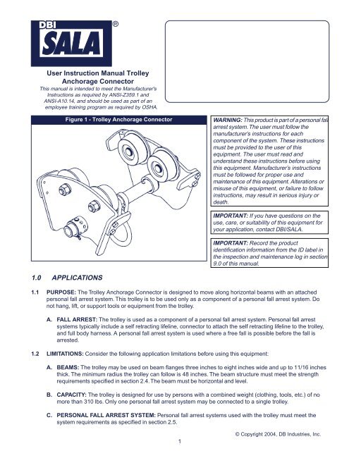
User Instruction Manual Trolley<strong>Anchorage</strong> <strong>Connector</strong>This manual is intended to meet the Manufacturer's<strong>Instructions</strong> as required by ANSI-Z359.1 andANSI-A10.14, and should be used as part of anemployee training program as required by OSHA.Figure 1 - Trolley <strong>Anchorage</strong> <strong>Connector</strong>WARNING: This product is part of a personal fallarrest system. The user must follow themanufacturer’s instructions for eachcomponent of the system. These instructionsmust be provided to the user of thisequipment. The user must read andunderstand these instructions before usingthis equipment. Manufacturer’s instructionsmust be followed for proper use andmaintenance of this equipment. Alterations ormisuse of this equipment, or failure to followinstructions, may result in serious injury ordeath.IMPORTANT: If you have questions on theuse, care, or suitability of this equipment foryour application, contact DBI/SALA.IMPORTANT: Record the productidentification information from the ID label inthe inspection and maintenance log in section9.0 of this manual.1.0 APPLICATIONS1.1 PURPOSE: The Trolley <strong>Anchorage</strong> <strong>Connector</strong> is designed to move along horizontal beams with an attachedpersonal fall arrest system. This trolley is to be used only as a component of a personal fall arrest system. Donot hang, lift, or support tools or equipment from the trolley.A. FALL ARREST: The trolley is used as a component of a personal fall arrest system. Personal fall arrestsystems typically include a self retracting lifeline, connector to attach the self retracting lifeline to the trolley,and full body harness. A personal fall arrest system is used where a free fall is possible before the fall isarrested.1.2 LIMITATIONS: Consider the following application limitations before using this equipment:A. BEAMS: The trolley may be used on beam flanges three inches to eight inches wide and up to 11/16 inchesthick. The minimum radius the trolley can follow is 48 inches. The beam structure must meet the strengthrequirements specified in section 2.4. The beam must be horizontal and level.B. CAPACITY: The trolley is designed for use by persons with a combined weight (clothing, tools, etc.) of nomore than 310 lbs. Only one personal fall arrest system may be connected to a single trolley.C. PERSONAL FALL ARREST SYSTEM: Personal fall arrest systems used with the trolley must meet thesystem requirements as specified in section 2.5.1© Copyright 2004, DB Industries, Inc.
D. FREE FALL: Personal fall arrest systems used with the trolley must be rigged to limit the free fall to six feet.See subsystem manufacturer’s instructions for more information.E. FALL CLEARANCE: There must be sufficient clearance below the user to arrest a fall before the user strikesthe ground or other obstruction. The clearance required is dependent on the following factors:• Elevation of Trolley • Connecting subsystem length• Deceleration distance • Movement of harness attachment element• Worker height • Free fall distanceSee personal fall arrest system manufacturer’s instructions for more information.F. TROLLEY LOAD ANGLE: Loads imposed on the trolleyby the personal fall arrest system must remain withinthirty degrees of the vertical center line of the beam. SeeFigure 2.Figure 2 - Trolley Load AngleG. ENVIRONMENTAL HAZARDS: Use of this equipment inhazardous environments may require additionalprecautions to reduce the possibility of injury to the useror damage to the equipment. Hazards may include, butare not limited to; heat, caustic chemicals, corrosiveenvironments, high voltage power lines, explosive ortoxic gases, moving machinery, and sharp edges.H. TRAINING: This equipment is intended to be installedand used by persons trained in its application and use.1.3 APPLICABLE STANDARDS: Refer to applicable local, state,and federal (OSHA) requirements governing this equipmentfor more information on anchorage connectors andassociated system components, including OSHA 1910.66,appendix C and OSHA1926.502.2.0 SYSTEM REQUIREMENTS2.1 COMPATIBILITY OF COMPONENTS: DBI/SALA equipment is designed for use with DBI/SALA approvedcomponents and subsystems only. Substitutions or replacements made with non-approved components orsubsystems may jeopardize compatibility of equipment and may affect the safety and reliability of the completesystem.2.2 COMPATIBILITY OF CONNECTORS: <strong>Connector</strong>s are considered to be compatible with connecting elementswhen they have been designed to work together in such a way that their sizes and shapes do not cause their gatemechanisms to inadvertently open regardless of how they become oriented. Contact DBI/SALA if you have anyquestions about compatibility.<strong>Connector</strong>s (hooks, carabiners, and D-rings) must be capable of supporting at least 5,000 lbs. (22.2kN).<strong>Connector</strong>s must be compatible with the anchorage or other system components. Do not use equipment that isnot compatible. Non-compatible connectors may unintentionally disengage. See Figure 3. <strong>Connector</strong>s must becompatible in size, shape, and strength. Self locking snap hooks and carabiners are required by ANSI Z359.1 andOSHA, an d in Canada, by CSA Z259.12.2.3 MAKING CONNECTIONS: Only use self-locking snap hooks and carabiners with this equipment. Only useconnectors that are suitable to each application. Ensure all connections are compatible in size, shape andstrength. Do not use equipment that is not compatible. Ensure all connectors are fully closed and locked.DBI/SALA connectors (snap hooks and carabiners) are designed to be used only as specified in each product’suser’s instructions. See Figure 4 for inappropriate connections. DBI/SALA snap hooks and carabiners should notbe connected:2
Figure 3 - Unintentional Disengagement (Roll-out)If the connecting element that a snap hook (shown) or carabiner attaches to is undersized or irregular inshape, a situation could occur where the connecting element applies a force to the gate of the snap hook orcarabiner. This force may cause the gate (of either a self-locking or a non-locking snap hook) to open, allowingthe snap hook or carabiner to disengage from the connecting point.Small ring or othernon-compatiblyshaped element1. Force is applied to thesnap hook.2. The gate presses againstthe connecting ring.A. To a D-ring to which another connector is attached.3. The gate opens allowing thesnap hook to slip off.B. In a manner that would result in a load on the gate.NOTE: Large throat opening snap hooks should not be connected to standard size D-rings or similar objects which willresult in a load on the gate if the hook or D-ring twists or rotates. Large throat snap hooks are designed for use on fixedstructural elements such as rebar or cross members that are not shaped in a way that can capture the gate of the hook.C. In a false engagement, where features that protrude from the snap hook or carabiner catch on the anchor andwithout visual confirmation seems to be fully engaged to the anchor point.Figure 4 - Inappropriate ConnectionsD. To each other.E. Directly to webbing orrope lanyard or tieback(unless themanufacturer’sinstructions for boththe lanyard andconnector specificallyallow such aconnection).F. To any object which isshaped ordimensioned suchthat the snap hook orcarabiner will notclose and lock, or thatroll-out could occur.2.4 ANCHORAGE STRUCTURE STRENGTH: The structure to which the trolley is installed must sustain static loadsin the directions permitted by the personal fall arrest system of at least 5,000 lbs. When more than one trolley isinstalled on the same anchorage structure, the anchorage structure strength must be multiplied by the number ofpersonal fall arrest systems attached to the structure.3
From OSHA 1926.500 and 1910.66: <strong>Anchorage</strong>s used for attachment of a personal fall arrest system shall beindependent of any anchorage being used to support or suspend platforms, and must support at least 5,000 lbs.per user attached; or be designed, installed, and used aspart of a complete personal fall arrest system whichFigure 5 - End Stopsmaintains a safety factor of at least two, and issupervised by a qualified person.2.5 PERSONAL FALL ARREST SYSTEM: Personal fallarrest systems used with this equipment must meetapplicable local, state, and federal (OSHA) requirements.A personal fall arrest system incorporating a full bodyharness must be capable of arresting a user’s fall with amaximum arresting force of 1,800 lbs., and limit the freefall distance to six feet or less. The deceleration distancemust be 42 inches or less.3.0 INSTALLATION AND USEWARNING: Do not alter or intentionally misuse this equipment. Consult withDBI/SALA if using this equipment with components or subsystems other thanthose described in this manual. Some subsystem and component combinationsmay interfere with the operation of this equipment.Figure 6 - Fall ClearanceWARNING: Consult with your doctor if there is any reason to doubt your fitness tosafely absorb the shock from a fall arrest. Age and fitness can seriously affectyour ability to withstand falls. Pregnant women and minors must not use thisequipment.3.1 BEFORE EACH USE of this equipment inspect it according to section 5.0.3.2 PLAN your fall arrest system before installing and using this equipment.Consider all factors affecting your safety during use. The following listgives some important points to consider when planning your system:A. ANCHORAGE BEAM: Select a rigid anchorage beam that is capable ofsupporting the loads specified in section 2.4. Joints between beamsections must be flush to allow the trolley to pass over smoothly. Thebeam must have end stops at each end to prevent the trolley fromrolling off the beam. The end stops must be sized and positioned tosafely stop the trolley. The trolley should not catch or hang-up on theend stop; the trolley must be able to freely return in the oppositedirection after contacting the end stop. See Figure 5.B. FALL CLEARANCE: See Figure 6. There must be sufficient clearancein your fall path to prevent striking an object or lower level in the eventof a fall. The amount of clearance required is dependent on theapplication. See personal fall arrest system manufacturer’s instructionsfor information on calculating fall clearance.Figure 7 - Swing FallsC. SWING FALLS: See Figure 7. Swing falls occur when the anchoragepoint is not directly overhead. The force of striking an object in a swingfall may cause serious injury or death. Minimize swing falls by workingas directly below the anchorage point as possible. Do not permit aswing fall if injury could occur. Swing falls will significantly increase theclearance required when a self retracting lifeline or other variable lengthconnecting subsystem is used. If a swing fall situation exists in yourapplication contact DBI/SALA before proceeding.4
4.0 TRAINING4.1 The user and purchaser of this equipment must be familiar with the instructions, operating characteristics,application limits, and the consequences of improper use of this equipment. Users and purchasers must betrained in the correct care and use of this equipment.WARNING: Training must be conducted without exposing the trainee to a fall hazard. Training should be repeated on aperiodic basis.5.0 INSPECTION5.1 FREQUENCY:• Before Each Use: Inspect trolley according to sections 5.2 and 5.3.• Annually: The trolley must be inspected by a competent person other than the user. See sections 5.2 and5.3 for inspection guidelines.5.2 INSPECTION STEPS:Step 1.Step 2.Step 3.Inspect trolley for damage. Look for cracks or deformities. Look for excessive wear or damage to theanchorage point. All fasteners must be secure.Inspect trolley wheels. All wheels should turn freely and be undamaged.Inspect entire unit for corrosion.Step 4. The warning label must be present and fully legible. See section 8.0.Step 5. Record inspection results in section 9.0.WARNING: If this equipment is subjected to the forces of a fall arrest, it must be removed from service and destroyed, orreturned to DBI/SALA for inspection and repair.5.3 If inspection reveals an unsafe or defective condition remove from service and destroy or contact DBI/SALA forrepair.6.0 MAINTENANCE, SERVICING, STORAGE6.1 MAINTENANCE: Clean the trolley using water and mild detergent. Wipe dry with a clean cloth and hang to air dry.Do not force dry with heat. An excessive build-up of dirt, paint, etc. may prevent the trolley from working correctly.No lubrication is required.6.2 SERVICING: Servicing must be completed by an authorized service center. Authorization must be in writing.6.3 STORAGE: Store this equipment in a cool, dry, clean environment. Inspect the trolley after extended storage.8
7.0 SPECIFICATIONS7.1 MATERIALS:2103143Trolley: Steel Frame, shielded wheel bearingsLoad Bar: Alloy steelD-ring: Alloy steelPivot Point bow-tie clip cotter pin: bow 722103147Trolley: 304 stainless steel frameLoad Bar: 303 stainless steelBearings: 440 stainless steelWheels: 303 stainless steelAdjusters: 303 stainless steelD-ring: Forged 410 stainless steelFasteners: 18-8 stainless steelCotter Pins: 5/64 in. x 3/4 in., 18-8 stainless steel7.2 DIMENSIONS (in inches):9
8.0 LABELING8.1 This label must be present and fully legible:10
9.0 INSPECTION AND MAINTENANCE LOGDATE OF MANUFACTURE: _______________________________________________________________________MODEL NUMBER: ______________________________________________________________________________DATE PURCHASED: ________________________________________________________________________________INSPECTION DATEINSPECTION ITEMSNOTEDCORRECTIVE ACTIONMAINTENANCEPERFORMEDApproved By:Approved By:Approved By:Approved By:Approved By:Approved By:Approved By:Approved By:Approved By:Approved By:Approved By:Approved By:11
USACanada3965 Pepin Avenue 260 Export BoulevardRed Wing, MN 55066-1837Mississauga, Ontario L5S 1Y9Toll Free: 800-328-6146 Toll Free: 800-387-7484Phone: (651) 388-8282 Phone: (905) 795-9333Fax: (651) 388-5065 Fax: (905) 795-8777www.salagroup.comwww.salagroup.comThis manual is available for download at www.salagroup.com.I S O9 0 0 1Certificate No. FM 39709Form: 5902145Rev: D12