Stereoscopic 3D Copy & Paste - Disney Research
Stereoscopic 3D Copy & Paste - Disney Research
Stereoscopic 3D Copy & Paste - Disney Research

Create successful ePaper yourself
Turn your PDF publications into a flip-book with our unique Google optimized e-Paper software.
ight eye images. The pasted object should assume the correctorientation depending on the surface orientation in the target,which varies with the desired location for pasting.• The copied object disparities in the target should be such thatthe depth composition is correct with respect to the depth inthe target.To take these aspects into account for <strong>3D</strong> copy & paste introducesthe problem of recovering the depth information. Many existingmethods for two-view stereo have been presented to compute perpixeldisparities [Scharstein and Szeliski 2010]. However, for inputimages of arbitrary scenes the computed disparities are often inaccurate.Furthermore, another challenge is to seamlessly composite thecopied selection into the target. The aforementioned 2D copy &paste methods may result in smearing artifacts in the case wherethe backgrounds are dissimilar in texture. Only composition usingalpha mattes can seamlessly blend objects with dissimilar backgrounds[Wang and Cohen 2008]. High quality alpha mattes willrequire accurate segmentation of the object to be copied and pasted.Finally, direct rendering methods, e.g., forward mapping or geometrymesh approximation, may result in artifacts in the case of inaccuratedepth maps.Contributions To address these challenges, we have developedan end-to-end system for <strong>3D</strong> copy & paste with the following additionalcontributions:• Automatic propagation of the segmentations from left eye toright eye image (Section 3.2).• Registration with respect to the local underlying support surfacein the target (Section 3.3.1).• Rendering using stereo billboards, which avoids the so-called“cardboarding” effect and preserves the original stereo volumeof the source selection (Section 3.3.3).• Generation of contact shadows by transferring the disparitymap to the target and using an image space ambient occlusionapproach (Section 3.3.5).Paper Organization The remainder of this paper is organized asfollows: we discuss related work in Section 2, and a detailed descriptionof our system is given in Section 3, results obtained withour system are presented in Section 4, a discussion of the presentedsystem and outlook on future work is given in Section 5, and finallySection 6 provides concluding remarks.2 Related WorkWe summarize prior work that is relevant to the challenges describedin the previous section and to the components of our system,which we describe in the following. We furthermore describehow we address some of the presented problems.Disparity Maps An important requirement of our system iscomputing disparity maps. Many two-view stereo disparity mapmethods, classified according to Scharstein and Szeliski [2002],have been reported in the literature and their relative scores arelisted [Scharstein and Szeliski 2010]. However, to date no methodcan produce accurate disparity maps for arbitrary input images suchas those typically found in people’s digital photo collections. Oursystem therefore aims to be robust with respect to depth map inaccuracies.Segmentation Accurate segmentation is inherently user assistedand iterative. Rother et al. [2004] describe a method that iterativelyapplies graph cuts optimization. Users may provide additionalhints to refine the segmentation. Liu et al. [2009b] let theuser paint strokes to denote foreground object and an incrementalgraph cuts scheme updates the segmentation in real-time. Multiobjectsegmentation for both methods would require a significantamount of user interaction. Lu et al. [2007] describe a multi-classsegmentation method, but this can handle only a small number ofdistinct classes and is computationally expensive. To allow for easymultiple object segmentation we combine the fast cluster-mergingmethod by Ning et al. [2010], and mean-shift clustering [Comaniciuand Meer 2002].Pop-up light field [Shum et al. 2004] is an image-based renderingsystem that models a sparse light field using a layered representation.In this system, the user interactively segments layers forpop-up until some desired quality is met. Our system shares somesimilarities with pop-up light field, but we work with stereoscopicinput instead of sparse light fields. In addition, our layers are notflat, but we preserve stereo volume using our stereo billboards. Finally,we focus on editing using copy & paste, while pop-up lightfield is mainly concerned with high quality rendering.Cosegmentation Propagating the segmentations from one eyeimage to the other eye image is related to cosegmentation. Cosegmentationaims at segmenting the common parts between a pair or asequence of images. Rother et al. [2006] exploit histograms for consistencybetween foreground objects in images. Cheng et al. [2007]encode the consistency between objects in frames within a priorand solve a mixture model. Zitnick et al. [2005] aim for consistentsegmentation and motion simultaneously, using segment shape andoptical flow between images as constraints and finally solving anenergy minimization problem. Motion, optical flow, and trackinghave also been proposed in segmentation propagation for video sequences[Chuang et al. 2002; Agarwala et al. 2004]. Rather thanrelying on multiple frames, or modeling the consistency betweenobjects explicitly, we have chosen to adopt Video Snapcut [Bai et al.2009] which propagates a set of local windows along the segmentationcontour with associated color and shape information.<strong>Copy</strong> & <strong>Paste</strong> <strong>Copy</strong> & paste using Poisson image editing [Pérezet al. 2003] has the advantage that no accurate segmentation is necessary,but requires care to be taken to avoid smearing in the case ofdissimilar backgrounds. Drag and Drop Pasting [Jia et al. 2006] attemptsto avoid smear by computing an optimal boundary for Poissonblending. However this method still will not produce desiredresults for multiple (partially occluding) objects of different textures.Alpha matting [Wang and Cohen 2008] on the other handwill be able to handle such cases, and we compute alpha mattes forall segmentations in our system.In Photo Clip-Art [Lalonde et al. 2007] objects are inserted into atarget image from a database of pre-segmented and labeled images.The <strong>3D</strong> scene structure, and lighting are estimated by image analysisand to determine which object to retrieve from the database. Inour case the user explicitly selects the objects to be copied from andpasted into stereoscopic <strong>3D</strong> images, and we address the challengesthat arise with this.Stereo Editing & Display Several stereoscopic editing approachesexist. <strong>Stereoscopic</strong> Inpainting [Wang et al. 2008] describesa segmentation-based method which exploits disparity mapsto fill in missing depth and color due to occlusion in stereoscopicimages. Editing methods for manipulating stereo parameters, e.g.,stereo baseline, compute disparity maps to adjust the parameters locallyor globally [Lang et al. 2010; Koppal et al. 2010; Wang andSawchuk 2008]. A commercial stereo editing tool we are currentlyaware of is the Ocula plug-in for Nuke [The Foundry 2010]. Thefocus in these methods is either on foreground object removal, colorcorrection, alignment correction, or stereo view synthesis ratherthan object copy & paste.
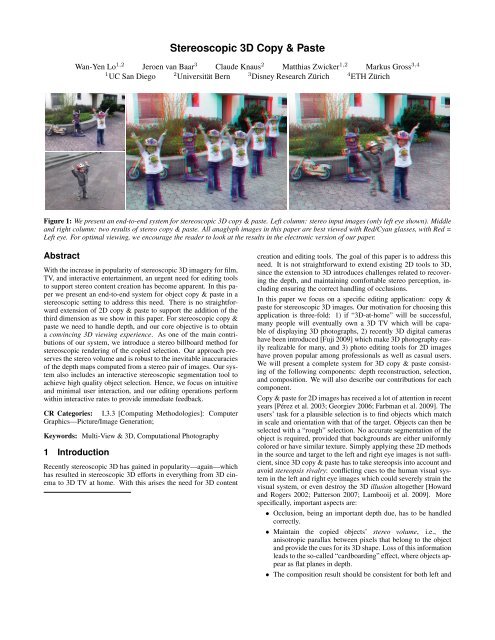
Iteration 0 Iteration 1 Iteration 2 Iteration 4Iteration 0 Iteration 1k = 10 k = 700(a) Mean-shift kernel adjustment (k = kernel size)(c) Segmentation refinementIteration 2Iteration 4k = 1000 k = 5000(b) Interactive cluster merging(d) Localized classifiers(e) Propagation resultsFigure 3: (a) Adjusting the kernel size can ease multi-object segmentation, because the largest clusters usually correspond to separate objects.(b) With a larger kernel size, the user is able to do the clustering with less strokes. (c) Segmentation refinement of the pineapple through fouriterations of graph cuts optimization. The corresponding probability maps estimated from overlapping localized classifiers are shown in (d).Classifier windows are only defined along the segmentation boundary, with some outlined in blue for illustration purposes. Green denotevalues based on local GMMs, while red values are based on the global GMM. The intensity directly corresponds to the probability. As thesegmentation is improved, the number of red windows decreases. (e) Propagation results from the left eye image to the right eye image. Pixelswith unknown segmentation are shown in white.ground surfaces, the foreground objects’ delicate contours requirea smaller mean-shift kernel size to better preserve details. We thusemploy the following scheme: the user adjusts the kernel size untilthe foreground objects are sufficiently clustered into an initialsegmentation (Figure 3a), next the user provides strokes to mergeclusters and improve the segmentation of the foreground objects(Figure 3b). These two steps can be repeated until some desiredsegmentation of the foreground objects has been achieved. The remainingclusters of the background surface can then be merged withonly a small number of strokes. Please see our accompanying videofor further demonstration.Besides using color information, we further exploit the disparitiesas a fourth channel in the mean-shift to improve the cluster boundaries,since disparities computed earlier already largely have discontinuitiesalong object silhouettes. Furthermore, the user can adjustthe kernel size adaptively for each object.We merge clusters using the maximal-similarity merging mechanism[Ning et al. 2010]. Clusters covered by the users’ stroke arefirst merged and marked as selected, and the selection is then propagatediteratively. More specifically, if cluster R is selected, wemerge cluster Q with R if:1. R and Q are adjacent, and2. ρ(R, Q) = max ρ(Q, S).S∈N (Q)Here N (Q) denotes the set of adjacent clusters to Q, and ρ(R, Q)measures the similarity of two clusters in color and depth. Instantvisual feedback is provided to the user during sketching, similarto Paint Selection [Liu et al. 2009b], allowing the user to decidewhether to continue or stop sketching.Segmentation refinement with localized classifiers User inputstrokes help differentiate objects in the scene. However, dueto color ambiguity or estimation errors in the disparity maps, thecontours of the merged clusters may not fit the object boundaryaccurately, as shown in iteration 0 of Figure 3c. Therefore, aftereach stroke sketch, the contours are refined by applying graphcuts optimization [Boykov et al. 2001] using overlapping localizedclassifiers [Bai et al. 2009]. Bai et al. use the localized classifiersto propagate a segmentation in a current frame to subsequentframes in a video sequence. In our work, we use a similar methodfor both contour refinement in the left image and for propagatingthe segmentation to the right image. We first discuss the contourrefinement for the segmentation in the left image.Bai et al. [2009] assume an accurate segmentation of the first frameas input. They then define a set of overlapping windows whose centerslie on the segmentation boundary, shown in Figure 3d. Eachwindow contains both background pixels (black) and foregroundobject pixels (green or red). Color statistics for each window aregathered, and a classifier assigns to every foreground pixel withinthat window, a probability of that pixel belonging to the foreground.Bai et al. advocate using small local windows. However, as statedabove, our initial segmentation may be inaccurate and hence, the localstatistics for small windows may be incorrect. Larger windowswould then be required for the inaccurate areas along the boundary.Since there is no knowledge of where the inaccurate areas are, wecreate two different sized windows at each sampled location on theboundary: one small (30 × 30 pixels) and one larger (60 × 60 pixels).For each window we build a Gaussian Mixture Model (GMM)in the Luv color space using local color statistics. In addition, weuse information from the whole image to build a global GMM. Foreach window size we then compute the model confidence for bothlocal and global GMMs (see Equation 2 in [Bai et al. 2009]), and wepick the one with the highest confidence. We run several iterationsof 2-label graph cuts refinement for each input stroke. After eachiteration we update the local classifiers along the new boundary.The refinement results are shown in Figure 3c, and the correspondinglocal windows in Figure 3d (with foreground pixels in windowsusing local GMM in green, and in windows using global GMM inred).Consistent propagation. To avoid the need for the user to repeatthe segmentation procedure for the right image, we propagatethe segmentation result from the left image. We exploit the dispar-
ity map and only propagate those pixels with coherent disparitiesbetween the left and right images, since those pixels tend to haveclassifiers with strong confidence. A pixel is said to have coherentdisparities if the difference between the disparity from the left tothe right image, and the disparity from the right to the left image isone pixel or less. The initial propagation result, i.e., iteration 0, isshown in Figure 3e. Since the image after propagation is initiallysparsely segmented, we also propagate the local classifiers from theleft image. However, we compute a new global GMM on the secondimage using only pixels with coherent disparities. We compute theconfidence values as described above and pick the one with highestconfidence. We perform several iterations of k + 1-label graph cutsfor global refinement for k partitioned segments. An example isshown in Figure 3e. In addition, if the automatic propagation doesnot give the desired quality of segmentation, the user may provideadditional strokes for refinement.3.3 CompositionIn the final component of our system the user composites (pastes)the selection in the target images. To support interactive explorationof the location for pasting, we aim for interactive performancewhile the user observes the resulting composite in stereo<strong>3D</strong>. However, as explained in Section 1, composition needs to takethe various aspects related to stereopsis into account: target depthcomposition, consistency, occlusions, and stereo volume. To addressthese aspects we perform the following steps:• Alignment of the pasted object with the local underlying surfacein the target.• Constraining the rotation of the pasted object to avoid the needfor in-painting or object completion.• Stereo volume preservation using stereo billboards.• Depth sorting to determine the correct visibility, i.e., occlusions.• Shadow estimation using the depth map and an ambient occlusiontechnique.Inaccuracies in the depth maps preclude direct artifact free renderingof the selection, either using, for example, point sample rendering[Zwicker et al. 2002], or mesh fitting [Zitnick et al. 2004].For robustness with respect to inaccuracies in the depth maps weintroduce the stereoscopic extension of billboard rendering whichwe have labeled stereo billboards. In the remainder of this Sectionwe will explain the above steps in more detail. For all our methods,we represent the geometry (point clouds) of both source andtarget scenes in a common coordinate frame. We define the centerof projection of the left eye camera as the origin of a <strong>3D</strong> coordinatesystem, and align the source and target camera to lie at the origin ofthis frame.3.3.1 Local Surface Orientation AlignmentIn the real world, objects are typically placed on some supportingsurface, e.g., a table or a sidewalk. Therefore, when an object iscopied from a source to a target image, our system aims to orient itin such a way that its support surface in the source becomes alignedwith an appropriate support surface in the target. As an exampleconsider the situation in Figure 4. When the pineapple from thesource scene on the left is copied into the target on the right, weaim to align the supporting table surfaces. This registration problemcould be solved using a general point cloud registration technique[Besl and McKay 1992]. We observe, however, that in practiceobjects are mostly placed onto planar support surfaces. Thereforewe use a simple strategy to align supporting planes.During the Selection step the images have been segmented, andeach foreground object and background surface is represented by asourcetargettablewalltableobjectwalltablealign table to wallalign table to tableFigure 4: Left: Source and target scene images (left eye) with differentorientations of the support surfaces. Middle+Right: After thepineapple is copied and pasted into the target scene, we compute atransformation for best alignment. In this case, there are two possiblealternatives, but the best choice would be to align the source’stable surface to the target’s table surface.segment. For a selected object in the source we define a set S ofneighbor segments. For example in Figure 4 the pineapple has thetable as its neighbor segment. When the object is pasted into thetarget, S will overlap with a set Ŝ of segments in the target scene.In the example of Figure 4, Ŝ contains the target’s table and wallsegments. Exploiting the fact that support surfaces typically areplanar, we estimate a least squares fitting plane for each s ∈ S andŝ ∈ Ŝ. For each segment in {S, Ŝ} we define a coordinate frame(R, t), with rotation R : R 3 → R 3 and translation t. We define tas the centroid of the <strong>3D</strong> points associated with the segment, and Ris computed from the normal of the estimated plane. We then aimto find the two segments s ∗ and ŝ ∗ with the most similar orientation,i.e., they minimize the rotation required to align the source andtarget segment:(s ∗ , ŝ ∗ ) = argmin ‖ RŝR −1s ‖. (1)s∈S,ŝ∈ŜThe desired alignment transformation T A(x) = R A(x) + t A is thetransformation that aligns these two segments. It can be computedasR A = Rŝ∗R −1s ∗ ,t A = tŝ∗ − R A(t s ∗). (2)Instead of using the entire segments, in practice we only use informationfrom partial segments. Partial segments are determined bytaking a predefined area around the selected object, e.g., the rectangularorange area around the pineapple in Figure 4. We denote suchpartial segments as patches.3.3.2 Rotation ConstraintsIf one could move an object freely in <strong>3D</strong>, parts that previously werehidden would become visible, as shown in Figure 5a. With stereoscopicinput images we have no data available for the invisible partsand hence, in-painting or object completion techniques would berequired to handle such rotations. To avoid these difficult tasks ofin-painting and object completion, we try to keep the object’s “forwardfacing” orientation of the source images. We accomplish thisby rotating the object around the normal of the support plane computedduring the alignment step.Assume t is the centroid of the object in the source scene, and ˆt isits new location after being pasted into the target scene. With thealignment transformation in Equation 2 we get:ˆt = T A(t) = R A(t) + t A. (3)We denote the up vector of the camera as u, and determine the angleθ between the projections of t and ˆt onto the ground plane (see Figure5(a)). We can then apply a corresponding rotation R F to ensure
239–256.BOYKOV, Y., VEKSLER, O., AND ZABIH, R. 2001. Fast approximateenergy minimization via graph cuts. IEEE Trans. onPattern Anal. and Mach. Intell. 23, 11, 1222–1239.CHUANG, Y.-Y., AGARWALA, A., CURLESS, B., SALESIN,D. H., AND SZELISKI, R. 2002. Video matting of complexscenes. In Proc. of SIGGRAPH 2002, ACM Press / ACM SIG-GRAPH, J. F. Hughes, Ed., ACM, 243–248.COMANICIU, D., AND MEER, P. 2002. Mean shift: A robustapproach toward feature space analysis. IEEE Trans. on PatternAnal. and Mach. Intell. 24, 603–619.DONG SEON, C., AND FIGUEIREDO, M. A. T. 2007. Cosegmentationfor image sequences. Int. Conf. on Image Anal. and Proc.,635 –640.FARBMAN, Z., HOFFER, G., LIPMAN, Y., COHEN-OR, D., ANDLISCHINSKI, D. 2009. Coordinates for instant image cloning.ACM Trans. on Graph. 28, 3 (Aug.).FUJI, 2009. Finepix REAL <strong>3D</strong> W1.http://www.fujifilm.com/products/3d/camera/finepix real3dw1/.FUKUDA, K., WILCOX, L. M., ALLISON, R., AND HOWARD,I. P. 2009. A reevaluation of the tolerance to vertical misalignmentin stereopsis. Journal of Vision 9, 2 (February), 1–8.GEORGIEV, T. 2006. Covariant derivatives and vision. Proc. ofEuropean Conf. on Comp. Vision 4, 56–69.HARTLEY, R. I., AND ZISSERMAN, A. 2004. Multiple View Geometryin Computer Vision, second ed. Cambridge UniversityPress, ISBN: 0521540518.HOWARD, I. P., AND ROGERS, B. J. 2002. Seeing in Depth,Basic Mechanics & Depth Perception, vol. 1 & 2. I Porteous,Thornhill, Ontario.JIA, J., SUN, J., TANG, C.-K., AND SHUM, H.-Y. 2006. Dragand-droppasting. ACM Trans. on Graph. 25, 3 (July), 631–637.KOPPAL, S., ZITNICK, C., COHEN, M., KANG, S., RESSLER, B.,AND COLBURN, A. 2010. A viewer-centric editor for stereoscopiccinema. IEEE Comp. Graph. and Appl. Preprint.LALONDE, J.-F., HOIEM, D., EFROS, A. A., ROTHER, C.,WINN, J., AND CRIMINISI, A. 2007. Photo clip art. ACMTrans. on Graph. 26, 3 (July).LAMBOOIJ, M., IJSSELSTEIJN, W., FORTUIN, M., AND HEYND-ERICKX, I. 2009. Visual discomfort and visual fatigue of stereoscopicdisplays: A review. Journal of Imaging Science and Tech.53, 3, 030201.LANG, M., HORNUNG, A., WANG, O., POULAKOS, S., SMOLIC,A., AND GROSS, M. 2010. Nonlinear disparity mapping forstereoscopic 3d. ACM Trans. on Graph. 29, 4 (July).LIU, F., GLEICHER, M., JIN, H., AND AGARWALA, A. 2009.Content-preserving warps for 3d video stabilization. ACM Trans.on Graph. 28, 3.LIU, J., SUN, J., AND SHUM, H.-Y. 2009. Paint selection. ACMTrans. on Graph. 28, 3 (Aug.).LOOS, B. J., AND SLOAN, P.-P. 2010. Volumetric obscurance. InACM Symp. on Interactive <strong>3D</strong> Graph. and Games, ACM, NewYork, NY, USA, 151–156.LU, F., FU, Z., AND ROBLES-KELLY, A. 2007. Efficient graphcuts for multiclass interactive image segmentation. Proc. of theAsian Conf. on Comp. vision, 134–144.MAMMEN, A. 1989. Transparency and antialiasing algorithmsimplemented with the virtual pixel maps technique. IEEE Comp.Graph. and Appl. 9, 4, 43–55.NING, J., ZHANG, L., ZHANG, D., AND WU, C. 2010. Interactiveimage segmentation by maximal similarity based regionmerging. Pattern Recogn. 43, 2, 445–456.PATTERSON, R. 2007. Human factors of 3d displays. Journal ofthe Soc. for Information Disp., 15, 861–871.PÉREZ, P., GANGNET, M., AND BLAKE, A. 2003. Poisson imageediting. ACM Trans. on Graph. 22, 3 (July), 313–318.REINHARD, E., ASHIKHMIN, M., GOOCH, B., AND SHIRLEY, P.2001. Color transfer between images. IEEE Comp. Graph. andAppl. 21, 5, 34–41.RHEE, S.-M., ZIEGLER, R., PARK, J., NAEF, M., GROSS, M.,AND KIM, M.-H. 2007. Low-cost telepresence for collaborativevirtual environments. IEEE Trans on Vis. and Comp. Graph. 13,1, 156–166.ROTHER, C., KOLMOGOROV, V., AND BLAKE, A. 2004. ”grabcut”:interactive foreground extraction using iterated graph cuts.ACM Trans. on Graph. 23, 3 (Aug.), 309–314.ROTHER, C., MINKA, T., BLAKE, A., AND KOLMOGOROV, V.2006. Cosegmentation of image pairs by histogram matching.IEEE Conf. on Comp. Vision and Pattern Recog., 993–1000.SCHARSTEIN, D., AND SZELISKI., R. 2002. A taxonomyand evaluation of dense two-frame stereo correspondence algorithms.Int. Journal of Comp. Vision 47, 1/2/3, 7–42.SCHARSTEIN, D., AND SZELISKI, R., 2010. Middlebury StereoRepository. http://vision.middlebury.edu/stereo/.SHUM, H. Y., SUN, J., YAMAZAKI, S., LI, Y., AND TANG, C. K.2004. Pop-up light field: An interactive image-based modelingand rendering system. ACM Trans. on Graph. 23, 2 (Aug.), 143–162.SMITH, B., ZHANG, L., AND JIN, H. 2009. Stereo matching withnonparametric smoothness priors in feature space. IEEE Conf.on Comp. Vision and Pattern Recog., 485–492.TAGUCHI, Y., WILBURN, B., AND ZITNICK, C. L. 2008.Stereo reconstruction with mixed pixels using adaptive oversegmentation.IEEE Conf. on Comp. Vision and Pattern Recog.,1–8.THE FOUNDRY, 2010. Nuke - Ocula Plug-in.http://www.thefoundry.co.uk/.WANG, J., AND COHEN, M. F. 2008. Image and video matting: Asurvey. Foundations and Trends in Comp. Graph. and Vision 3,2, 97–175.WANG, C., AND SAWCHUK, A. A. 2008. Disparity manipulationfor stereo images and video. <strong>Stereoscopic</strong> Disp. and Appl. 6803,1, 68031E.WANG, L., JIN, H., YANG, R., AND GONG, M. 2008. <strong>Stereoscopic</strong>inpainting: Joint color and depth completion from stereoimages. In IEEE Conf. on Comp. Vision and Pattern Recog., 1–8.ZITNICK, C. L., AND KANG, S. B. 2007. Stereo for image-basedrendering using image over-segmentation. Int. Journal of Comp.Vision 75, 1, 49–65.ZITNICK, C. L., KANG, S. B., UYTTENDAELE, M., WINDER, S.,AND SZELISKI, R. 2004. High-quality video view interpolationusing a layered representation. ACM Trans. on Graph. 23, 3(Aug.), 600–608.ZITNICK, C. L., JOJIC, N., AND KANG, S. B. 2005. Consistentsegmentation for optical flow estimation. IEEE Int. Conf. onComp. Vision, 1308–1315.ZWICKER, M., PFISTER, H., VAN BAAR, J., AND GROSS, M.2002. Ewa splatting. IEEE Trans. on Vis. and Comp. Graph. 8,3, 223–238.