
You also want an ePaper? Increase the reach of your titles
YUMPU automatically turns print PDFs into web optimized ePapers that Google loves.
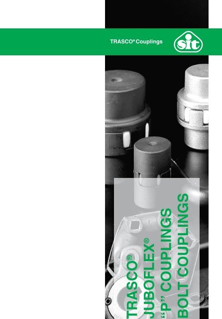
TRASCO ® <strong>Couplings</strong>TRASCO ®JUBOFLEX ®“P” COUPLINGSBOLT COUPLINGS
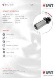
www.sitspa.comTRASCO ® couplingsDescriptionTRASCO ® flexible couplings consist of two metal hubs and anelastic gear ring which is resistant to oils, chemical agents andheat. The construction allows safe power transmission betweendriver and driven shafts, absorbing impact loads, and torsionalvibrations.In its class TRASCO ® coupling transmits more power in relationto the physical space occupied.It has a very compact design and allows safe power transmissionby absorbing peak loads and torsional vibrations.Moreover, the elastic deformation of the polyurethane gear ringcompensates angular and radial misalignments and also absorbssmall shaft length variation.The involute profile of the gear ring teeth prevents high stressconcentration on reduced surfaces and the crowned profileavoids the transmission of axial stress.The high duty factor of TRASCO ® couplings is due to the fact thatthe elastic element works under compression and never underflexion.TRASCO ® couplings are suitable for working in both horizontaland in vertical positions and easily support any load variation orreversal. The two coupling halves are electrically insulated fromeach other.TRASCO ®TRASCO ®“A” execution Spider “B” execution “BL” executionATEX 94/9/EC complianceIt is possibile to ask for specific certification for use in hazardousarea according to EC standard 94/9/EC. TRASCO couplings areavailable with specific mounting/operating instruction manual andconformity. For information, please contact our technical office.Hubs are available in cast iron GG25, die cast aluminum alloy orforged aluminum.Special request hubs are available in steel or cast iron GGG40.In the base execution, “GR” TRASCO ® couplings are available intwo different versions: precision “P” or economy “S”.In all other executions, only the precision type is manufactured.The difference between “P” and “S” type hubs is that in theprecision execution the circular sections of the hubs are precisionmachined, while in the economy execution, they are simplydeburred.The “S” version allows lower axial displacement as indicated in thetechnical performance table. Each hub is available in two types“A” and “B”, which can accommodate maximum bore size inmm corresponding respectively to the first and second number ofthe coupling designation.Besides the various executions shown in the catalogue, it isalways possible to manufacture coupling hubs for specialapplications.Direct drives (073.00)1
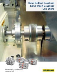
GRMP...AARwww.sitspa.com“GR” base programGRMP...BTRASCO ® couplings are dimensionally manufactured to hubtypes “A” and “B”, the difference being the maximum shaftdiameter which hubs can accept (corresponding respectively tothe first and second code number).The long hub execution “L” (allows full cover of the motor shaft) istIHPSMNSHIavailable in both “A” and “B” executions.Materials used for manufacture are:• cast iron grade GG25 (all sizes);• aluminum, diecasting• cast iron grade GGG40 and steel upon request.GRMP...AARGRMP...BFaEAFbBGTRASCO ®FgMozzo"A"Mozzo"B"FgLDimensional specification hubs in GG25HMH1 2 0 1 0 7 / 1 / C LFa FbFg [mm]E A BexecutionA B execution AL execution S N S BL execution M S N GType max maxII[mm] [mm] A B [mm] [mm] [mm] H [mm] L [mm] I [mm] H [mm] L [mm] I [mm] H [mm] L [mm] I [mm] H [mm] L [mm] I [mm] [mm] [mm] [mm] [mm]t19/24* - 24 - - 40 - 40 25 66 - 25 66 - - P - - 50 - - 16 2 12 1824/32 24 32 8 10 55 40 55 30 78 24 30 78 - 50 128 44 60 128 - 18 2 14 2728/38 28 38 8 10 65 48 65 35 90 28 35 90 - 60 160 53 80 160 - 20 2,5 15 3038/45 38 45 10 12 80 66 80 45 114 37 45 114 - 80 214 72 110 214 - 24 3 18 3842/55 42 55 10 12 95 75 95 50 126 40 50 126 - 110 246 100 110 246 - 26 3 20 4648/60 48 60 12 12 105 85 105 56 140 45 56 140 - 110 278 99 140 278 - 28 3,5 21 51EA55/70 55 70 15 15 120 98 120 65 160 52 65 160 - 110 280 97 140 280 - 30 4 22 6065/75 65 75 15 15 135 115 135 75 185 61 75 185 - 140 315 126 140 315 - 35 4,5 26 6875/90 75 90 15 15 160 135 160 85 210 69 85 210 - 140 350 124 170 350 - 40 5 30 80MozzoMozzo90/100 90 100 20 20 200 160 180 100 245 81 100 245 81 170 "A" 425 151 210 425 "B" 191 45 5,5 34 100100/110 115 - 45 - 225 180 - 110 270 89 110 270 - - - - - - - 50 6 38 113110/125 125 - 55 - 255 200 - 120 295 96 120 295 - - - - - - - 55 6,5 42 127125/145 145 - 55 - 290 230 - 140 340 112 140 340 - - -L- - - - 60 7 46 147* Sintered steelDimensional specification hubs in aluminumTypeFamax[mm]Fbmax[mm]AFg [mm]executionBE[mm]A[mm]B[mm]FaFgL[mm]H[mm]GM1 2 0 1 0 7 / S1/ C L[mm] [mm]19/24 - 24 - 4 40 40 40 66 25 16 2 12 - 1824/32 24 32 6 22 55 40 55 78 30 18 2 14 24 2728/38 28 38 8 26 65 48 65 90 35 20 2,5 15 28 3038/45 38 45 10 36 80 66 77 114 45 24 3 18 37 3842/55 - 55 - 15 95 - 95 126 50 26 3 20 - 4648/60 - 60 - 24 105 - 105 140 56 28 3,5 21 - 51FgN[mm]FbBValid bore for “P” executionI[mm]G[mm]Order formGRM P 42/55 ALTRASCO ® GR hub“P” precise execution; “S” standard executionTipo“A” Execution ; Execution “B”Long hubGRMALU 38/45 ATRASCO ® GR aluminum hubTypeExecution “A” ; Execution “B”AR 19/24 RTRASCO ® GR spiderTypeYellow colour if not indicated,“R” red, “V” greenDirect drives (073.00)7
www.sitspa.comStock rangeHubs with finished bore H7, keyway, stop screwTypeMaterial*HubexecutionStock range bore [mm]10111214151618192022242528303235384042454850556065707580859019/24*ALU = Aluminum - AC = Steel - GG = Cast iron24/32 28/38 38/45 42/55 48/60 55/70 65/75 75/90 90/100ALU AC ALU GG ALU GG ALU GG ALU GGALU GG GG GG GG GGB B A B A B A B A B A B A B B A B B A B A B A A A• •• •• •• • •• • •• • •• •• • •• • ••• • •• • •• • •• • •• • •• • •• • •• • •• • • • ••••• • • • • • • •• • • • • • • •• • • • • • • •• • • • • • • •• • • • • • • • •• • • • • • • • •• • • • • • • •• • • • • • •• • • • • • •• • • • • • •• • • • • • • •• • • • • • • •• • • • • •• • • •• • •• ••••Setscew specifics per hub dimensionHub dimension P [mm] t [mm]19 M5 1024/32 M5 1028/38 M6 1538/45 M8 1542/55 M8 2048/60 M8 2055/70 M10 2065/75 M10 2075/90 M10 2590/100 M12 30100/100 M12 30110/125 M16 35125/145 M16 40PtGRMP....A8Direct drives (073.00)
HSMNHSwww.sitspa.com“GRB” taper bush seriesTRASCO ® couplings type GRB are manufactured in cast ironGG25. They combine the typical high performances of standardcouplings with the mounting and dismounting advantages offeredby the SER-SIT ® taper bush:-they are ready to be mounted;-they are manufactured in two different executions:IILB1Ø EØ BØ dHSMNHSØ dØ BB1 and B2 (see picture);• they solve the problem of fighting corrosion;• hubs type B1 may be axially moved for spider replacement;• they may be used in all types of machinery.B2HSMNHSØ EØ BØ dTRASCO ®Ø dØ BØ EØ BØ dØ dØ BB1ILIB2ILIØ dØ BType75/90 2517 (6545) 160 158 130 45 40I5I30 3690/100 * 3535 (9090) 200 180 223 89 45 5,5L34 70* Only “B1” executionTaper bushB2E[mm]B[mm]L[mm]28/38 1108 (2820) 65 65 66 23 20 2,5 15 -38/45 1108 (2820) 80 78 70 23 24 3 18 1542/55 1610 (4025) 95 94 78 26 26 3 20 1648/60 1615 (4040) 105 104 106 39 28 3,5 21 2855/70 2012 (5030) 120 118 96 33 30 4 22 2065/75 2012 (5030) 135 133 101 33 35 4,5 26 19B1H[mm]Ø EØ BØ dM[mm]HSMNS[mm]HSN[mm]Ø dØ BI[mm]HSMNHSØ dØ BØ EØ BØ dØ dØ BILIB1HSMNHSOrder formGRMB 42/55 B1AR 19/24 RØ EØ BTRASCO ® GRMB hub for taper lockTypeØ dILIØ dØ B“B1” Execution ; “B2” ExecutionSpiderTypeYellow if not indicated, “R” red, “V” greenTaper locktypeTransmissibletorque[Nm]1108 (2820) 1501610 (4025) 4901615 (4040) 4902012 (5030) 8002517 (6545) 13003535 (9090) 5000Direct drives (073.00)9
www.sitspa.com“GRL CAL3” series with intermediate shaftThis series allows the joining of two shafts (even two spaced)through two TRASCO ® couplings and an intermediate shaft(length “LR2”) of customized dimension, fixed with hubs throughshrink-disc.The presence of two polyurethane elements allows highdampening capability and large radial misalignments.Hubs are classically made of cast-iron, while shafts are madeof steel; though different materials can be used according todifferent applications.L L2L1E L3S N SØ DHØ dØ dRLR2LZR2TypeDimensions [mm] GRL-CAL3Internal hubExternal hubSITLOCK 3 elementsdmin dmaxLR2L Intermediate shaftL2DH L1 L3 L E N s L2LZR2Screwmin.TAL1E L3Type Din 912-12.9[Nm]dR C [Nm/Rad·m]S N SM·L14 4 15 30 11 26 50 13 10 1,5 61,5 109 LR2+22 10x2.0 68,36 10x16 M4X10 4,919/24 6 24 40 25 26 67 16 12 2 81 120 LR2+50 12x2.0 130 12x18 M4X10 4,924/32 8 28 55 30 38 86 18 14 2 102 156 LR2+60 20x3.0 954,9 20x28 M6X18 1728/38 10 38 65 35 45 100 20 15 2,5 117,5 177 LR2+70 25x2.5 1811 25x34 M6X18 17Ø DHØ d38/45 12 45 80 45 45 114 24 18 3 135 192 LR2+90 32x3.5 5167 32x43 M6X18 1742/55 14 55 95 50 52 128 26 20 3 151 214 LR2+100 40x4.0 11870 40x53 M6X18 1748/60 15 60 105 56 70 154 28 21 3,5 178,5 261 LR2+112 45x4.0 17486 45x59 M8X22 41LR25570 20 74 120 65 80 175 30 22 4 280207/ 201 288 2/ CLLR2+130 55x4.0 33543 LZR2 55x71 M8X22 4165/75 22 80 135 75 80 190 35 26 4,5 220,5 307 LR2+150 60x4.0 44362 60x77 M8X22 41Ø dROrder formGRM 48/60 per cal 3AR 38/45 RTRASCO ® GR hubTypeSpiderTypeYellow if not indicated, “R” red, “V” greenIntermediate shaft on request12Direct drives (073.00)280207/ 2/ CL
www.sitspa.com“GRF” flange seriesEAThis series, with flanges, has been developed for applications onheavy machinery and to combine different shafts and flangessolutions.• Shaft-shaft: using two hubs type “BF”, allows the replacement ofthe elastic element without traversing of either motor-machine ordriven-machine.• Shaft-flange: using one hub type “CF” and one type “GR”.• Flange-Flange: using two S hubs N Stype “CF”. ILcEABcPNrFaGBbFaAEaHMVHTRASCO ®LbBFCFEAFaGBbFaAEaFaGCDEaHSNMSVHIGRMP...AS N SH M VARBFBFCFLcCFTypeFamin[mm]Famax[mm]EAFaE[mm]Ea[mm]GA[mm]PC[mm]NrCDEaD[mm]Nr[mm]P[mm]G[mm]19/24 - 19 40 65 40/32 40 50 5 4,5 18 25 26 1,5 17 8 16 2 12 74 49Bc24/32 9 24 55 80 55/40 55 65 5 4,5 27 30 31 1,5 22 8 18 2 14 86 5628/38 9 28 65 100 65/48 65 80 6 6,5 30 35 36 1,5 25 10 20 2,5 15 100 6538/45 11 38 80 115 66 80 95 6 6,5 38 45 46 1,5 35 10 24 3 18 124 7942/55 11 42 95 140S75N S95 115 6 9 46 50 51 2 38 12 26 3 20 138 8848/60 13 48 105 H 150 M 85V105 125 8 9 51 56 57 2 44 12 28 3,5 21 152 9655/70 16 55 120 175 98 120 145 8 11 60 65 66 2 49 16 30 4 22 176 11165/75 16 65 135 190 115 135 160 10 11 68 75 76 2 59 16 35 4,5 26 201 12675/90 16 75 160 215 135 160 185 10 14 80 85 87 2,5 66 19 40 5 30 229 144Lb230107/ 1/ CL90/100 21 90 200 260 160 200 225 12 14 BF 100 100 102 3 80 20 45 5,5 34 265 165100/110 46 115 225 285 180 225 250 12 14 113 110 112 4 85 25 50 6 38 295 185110/125 56 125 255 330 200 255 290 12 18 127 120 122 4 94 26 55 6,5 42 321 201125/145 56 145 290 370 230 290 325 16 18 147 140 142 5 110 30 60 7 46 370 230Valid bore for “P” execution.EAFaGBbFaAEaH[mm]Bb[mm]Bc[mm]I[mm]V[mm]M[mm]S[mm]N[mm]Lb[mm]Lc[mm]CFOrder formS N S IShaft side flange H“BF” MexecutionV HTypeBFGRMP...AARBFGRFBF 48For hub “GR” order form please see TRASCO ® GR base programLcEAFaGCDEaBcPCFGRFCF 48NrRing side flange “BF” and “CF” executionTypeCFCFNrNumber of screwsS N SH M V230107/ 1/ CLDirect drives (073.00)13
www.sitspa.comLbNrAFGBcDP“GRF C” flange SseriesN SH M VThe GRF C series has the same characteristics as the BF series, while being compact in dimension.BFNCFNLcEAFaGBbBFaDEEAFaGBcCPNrDEHS N SM V HIPHSNMSVBFNCFNLbBFN240107/ 2/ CLTypeFamin[mm]Famax[mm]E[mm]A[mm]B[mm]H[mm]I[mm]Lb[mm]Lc[mm]24/32 9 24 55 40 36 30 22 86 56 8 18 2 14 31 1,5 27 45 8 36 M528/38 9 28 65 48 42 35 25 100 65 10 20 2,5 15 36 S 1,5N 30 S 54 I 8 44 M638/45 11 38 80 66 52 45 35 124 79 10 24 3 18 H 46 1,5 M V38 66H8 54 M842/55 11 42 95 75 62 50 38 138 88 12 26 3 20 51 2 46 80 12 65 M848/60 13 48 105 85 70 56 44 152 96 12 28 3,5 21 57 2 51 90 12 75 M855/70 16 55 120 98 80 65 49 176 111 16 30 4 22 66 2 60 102 8 84 M1065/75 16 65 135 115 94 75 59 201 126 16 35 4,5 26 76 2 68 116 12 96 M1075/90 16 75 160 135 108 85 66 229 144 19 40 5 30 87 2,5 80 136 15 112 M1290/100 21 90 200 160 142 100 80 265 165 20 45 5,5 34 102 3 100 172 15 145 M16100/110 46 115 225 180 158 110 85 295 185 25 50 6 38 112 4 113 195 15 165 M16110/125 56 125 255 200 178 120 94 321 201 26 55 6,5 42 122 4 127 218 15 180 M20125/145 56 145 290 230 206 140 110 370 230 30 60 7 46 142 5 147 252 15 215 M20V[mm]M[mm]EAFaS[mm]N[mm]Bb[mm]GBc[mm]G[mm]DBb[mm]NrBFaC[mm]PNrDEP[mm]Valid bore for “P” execution.GRMP...AOrder formShaft side flange “BFN” executionTypeBFNARCFNMFNBFNGRFBFN 48For hub “GR” order form please see TRASCO ® GR base programGRFCFN 48Ring side flange “BFN” and “CFN” executionTypeLcCFNCFNCFNNrNumber of screwsEAFaCNrEGBcDP14Direct drives (073.00)HSNMSV
www.sitspa.com“GRS” double cardanic seriesIt allows compensation of high axial, radial and angular misalignment.Moreover, the use of the double spider allows fordouble the torsion angle and provides very high dampeningeffect.LØ EØ AØ FaØ GØ FbØ BTRASCO ®S N S S N SIM V MIH C HLFa Fb H V C M S N L E A B G ∆KrType[mm] [mm] [mm] [mm] [mm] [mm] [mm] [mm] [mm] [mm] [mm] [mm] [mm] [mm]GRMP...A24/32 9 - 24 11 - 32 30 16 52 18 2 14 112 AR 55 40 55 27 0,8928/38 9 - 28 11 - 38 35 18 58 20 2,5 15 128 65 48GRS65 30 138/45 11 - 38 13 - 45 45 20 68 24 3 18 158 80 66 80 38 1,1542/55 11 - 42 13 - 55 50 22 74 26 3 20 174 95 75 95 46 1,2648/60 13 - 48 13 - 60 56 24 80 28 3,5 21 192 105 85AR105 51 1,3655/70 16 - 55 16 - 70 65 28 88 30 4 22 218 120 98 120 60 GRMP...B 1,5265/75 16 - 65 16 - 75 75 32 102 35 4,5 26 252S135N S S115N S135 68 1,7575/90 16 - 75 16 - 90 85 36 116 40 5 30I286M160V135M160I80 290/100 21 - 90 21 - 100 100 40 130 45 5,5 34 H330 200 C 160 180 H 100 2,5Ø EØ AØ FaØ GØ FbØ B∆Kw[°]1°30’Valid bore for “P” executionGRMP...AARGRSOrder formFor hub “GR” order form please see TRASCO ® GR base programGRSARGRMP...BGRS 48/60Spacer elementTypeF a Bore of hub “A” mmF b Bore of hub “B” mm∆K r Maximum radial misalignment mm∆K w Maximum angular misalignment °Direct drives (073.00)15
www.sitspa.com“GR FRT” drum brake seriesThis series has been developed to suit drum-brake (FRT)transmissions.It is constituted as an elastic coupling screwed to the brake band.Components are either made of cast-iron (G25), spheroidalcast-iron (GS400), or steel according to application.Also, assembling of different dimensioned brake bands to anykind of coupling is allowed. See below tables.FRTFRTEAFaGCtVDFbB j6NrDbHSN SMHPBbLGR FRT - drum brakeDb x Bb 28 38 42 48 55 65 75 90 100 110 125W FRT[kg]J FRT[kg m 2 ]min -1withVmax30 m/s160x60 30 31 - - - - - - - - - 2,12 0,01 3580200x75 35 36 38 39 41 - Cd - - - - - 3,45 0,03FRD2860250x95 43 44 46 47 49 50 52 - - - - 6,87 0,08 2290315x118 - - 55 56 58 59 61 64 - - - 14,95 0,28 1820630x236 - - - - - - 107 110 112 115 119 112,00 8,01 910710x265 - - - - - - S N -S- 123 126 130 161,00 14,90 810800x300 - - - - - - V - - - - 144 202,00 27,20 720H M HFa;Fb max [mm] FRDEAFaG400x150 - - 68 69 71 72 74 77 79 82 - 31,20 0,89 1430500x190 - - - - - 87 89 92 94 97 101 60,00 2,70 1150TypeFa;Fbmin[mm]FaFb(GG25)Fb(GS400)Fb(Steel)E[mm]A[mm]Ba B[mm] L28 FR 10 28 20 22 24 65 48 38 35 90 30 8 6,5 20 2,5 15 52 M638 FR 12 38 28 32 34 80 66 50 45 114 38 8 7,5 24 3 18 66 M842 FR 14 42 30 38 42 95 75 60 50 126 46 12 9,5 26 3 20 80 M848 FR 15 48 35 45 48 105 85 68 56 140 51 12 10,5 28 3,5 21 90 M855 FR 20 55 42 50 55 120 98 78 65 160 60 8 12,5 30 4 22 102 M10010207/ 3/ CL65 FR 22 65 48 55 65 135 115 92 75 185 68 12 13,5 35 4,5 26 116 M1075 FR 30 75 58 70 75 160 135 106 85 210 80 15 15,5 40 5 30 136 M1290 FR 40 90 75 90 100 200 160 140 100 245 100 15 18,5 45 5,5 34 172 M16100 FR 45 115 - 100 - 225 180 156 110 270 113 15 20,5 50 6 38 195 M16110 FR 55 125 - 110 - 255 200 176 120 295 127 15 23,5 55 6,5 42 218 M20125 FR 55 145 - 130 - 290 230 204 140 340 147 15 27,5 60 7 46 252 M20H[mm]FbPj6BL[mm]D NrDaG[mm]NrV[mm]M[mm]S[mm]N[mm]D[mm]P[mm]FRTOrder formFor hub “GR” order form please see TRASCO ® GR base programGRFRTFRTGRFR 48EAFaBrake side hubCtTypeVB j6NrDbDGFbBand on request.PWFRT “GRFRT” weight kgS N SJFRT “GRFRT” moment of inertia kgm 2Nr Number of screws H M H16Direct drives (073.00)Bb
“GR FRD” brake disc seriesThis series has been developed to suit disc-brake (FRD)transmissions according to DIN 15431/15435.It is constituted as an elastic coupling screwed to the brake band.Components are either made of cast-iron (G25), spheroidalHSN SMBbLHPwww.sitspa.comcast-iron (GS400), or steel according to application.Also, assembling of different dimensioned brake bands to any kindof coupling is allowed. See below tables.TRASCO ®CdFRDGFbD NrDaHSNVMEAFaBj6SHPFRDBaLFRTGR FRD - brake discDa x Ba 28 38 42 48 55 65 75 90 100 110 125010207/ 3/ CL200x12,5 X X - - - - - - - - - 2,93 0,0154 3820250x12,5 X X X X - - - - - - - 4,66 0,0376 3060315x16 - - X X X X X - - - - 8,62 0,1118 2430400x16 - - - X X X X X X X - 15,23 0,3152 1910500x16 - - - - X X X X X X X 23,96 0,7680 1530630x20 - - - - - X X X X X X 47,72 2,4264 1210710x20 - - - - - X X X X X X 60,93 3,9151 1080800x25 - - - - - - - X X X X 94,91 7,8790 950EAFaGCtVFbB j6Nr900x25 - - - - - - - - - X X 118,95 12,6091 850DDbW FRD[kg]FRTJ FRD[kg m 2 ]min -1withVmax40 m/sTypeFa;Fbmin[mm]FaFa;Fb max [mm]Fb(GG25)HSFb(GS400)N SMFb(Steel)E[mm]A[mm]B[mm]28 FR 10 28 20 22 24 65 48 38 35 90 30 8 6,5 20 2,5 15 52 28,5 M638 FR 12 38 28 32 34 80 66 50 45 114 38 8 7,5 24 3 18 66 37,5 M842 FR 14 42 30 38 42 95 75 60 50 126 46 12 9,5 26 3 20 80 40,5 M848 FR 15 48 35 45 48 105 85 68 56 140 51 12 10,5 28 3,5 21 90 45,5 M8Bb55 FR 20 55 42 50 55 120 98 78 65 160 60 8 12,5 30 4 22 102 52,5 M10LHP65 FR 22 65 48 55 65 135 115 92 75 185 68 12 13,5 35 4,5 26 116 61,5 M1075 FR 30 75 58 70 75 160 135 106 85 210 80 15 15,5 40 5 30 136 69,5 M1290 FR 40 90 75 90 100 200 160 140 100 245 100 15 18,5 45 5,5 34 172 81,5 M16100 FR 45 115 - 100 - 225 180 156 110 270 113 15 20,5 50 6 38 195 89,5 M16110 FR 55 125 - 110 - 255 200 176 120 295 127 15 23,5 55 6,5 42 218 96,5 M20125 FR 55 145 - 130 - 290 230 204 140 340 147 15 27,5 60 7 46 252 112,5 M20H[mm]L[mm]G[mm]NrV[mm]M[mm]S[mm]N[mm]D[mm]Cd[mm]P[mm]Order formFor hub “GR” order form please see TRASCO ® GR base programGRFRDGRFR 48Disc on request.Brake side hubTypeCdFRDEAFaGFbj6BD NrDaWFRD “GRFRD” disc weight kgJFRD “GRFRD” moment of inertia kgm 2NrNumber of screwsSNVSPDirect drives (073.00)17
www.sitspa.comTRASCO ® couplings weight and moment of inertiafig.1 fig.2 fig.3GRS aluminumfig.4 fig.5 fig.6Type19/2424/3228/3838/4542/5548/6055/7065/7575/9090/100100/110110/125125/145GR(A esecuz.)fig. 1GR(B esecuz.)fig. 1GR(AB esecuz.)fig. 1GRALU(esecuz. A)fig. 1GRALU(B esecuz.)fig. 1GRALU(AB esecuz.)fig. 1GRBfig. 2GRF(CF)fig. 3GRF(CFN)fig. 4W [kg] - 0,37 - - 0,14 - - 0,23 - - -J [kgm 2 ] - 0,0001 - - 0,00004 - - 0,00006 - - -W [kg] 0,56 0,78 0,67 0,22 0,31 0,26 - 0,3 0,18 0,42 0,14GRF(BFN)fig. 5SpacerelementGRSfig. 6J [kgm 2 ] 0,0002 0,0004 0,0003 0,00008 0,00015 0,00012 - 0,0003 0,00009 0,00018 0,00006W [kg] 0,92 1,25 1,1 0,36 0,49 0,43 1 0,58 0,3 0,69 0,22J [kgm 2 ] 0,0005 0,0009 0,0007 0,0002 0,00034 0,00027 0,0007 0,0008 0,00021 0,00041 0,00013W [kg] 1,97 2,5 2,25 0,77 0,98 0,9 1,7 0,8 0,313 0,933 0,35J [kgm 2 ] 0,0017 0,0027 0,002 0,0007 0,001 0,00084 0,0026 0,001 0,00047 0,00097 0,00035W [kg] 3,1 3,85 3,46 - 1,5 - 2,8 1,41 0,76 1,81 0,51J [kgm 2 ] 0,0035 0,006 0,0047 - 0,002 - 0,0036 0,004 0,0012 0,0023 0,0007W [kg] 4,2 5,3 4,75 - 2 - 4,7 1,62 0,89 2,27 0,67J [kgm 2 ] 0,006 0,01 0,008 - 0,004 - 0,0078 0,005 0,0017 0,0035 0,001W [kg] 6,4 7,8 7,1 - - - 5 2,82 1,47 3,55 0,97J [kgm 2 ] 0,012 0,02 0,015 - - - 0,012 0,012 0,0035 0,007 0,002W [kg] 9,7 11,8 10,8 - - - 6,9 3,46 1,89 4,89 1,43J [kgm 2 ] 0,024 0,035 0,03 - - - 0,014 0,017 0,0059 0,0123 0,004W [kg] 15,2 20,8 18 - - - 14,8 5,03 3 7,86 2,2J [kgm 2 ] 0,051 0,082 0,07 - - - 0,065 0,032 0,0125 0,0275 0,009W [kg] 26,2 30,2 28,2 - - - 35,4 7,9 4,87 13,54 3,9J [kgm 2 ] 0,13 0,17 0,15 - - - 0,162 0,073 0,033 0,108 0,025W [kg] 32,6 - - - - - - 13,5 7,55 20,15 -J [kgm 2 ] 0,22 - - - - - - 0,139 0,063 0,14 -W [kg] 45,5 - - - - - - 18,8 10,15 27,05 -J [kgm 2 ] 0,38 - - - - - - 0,255 0,11 0,242 -W [kg] 68,8 - - - - - - 27,4 14,9 40,9 -J [kgm 2 ] 0,76 - - - - - - 0,463 0,21 0,48 -Weight and moments of inertia are calculated on hubs with max diameter bore.18Direct drives (073.00)
www.sitspa.comTables for TRASCO ® couplings with taper or splined boresøøTRASCO ®Taper 1:5 per:BOSCH - BUCHER- LEDUC - DÜSTERLOHCode ø d + 0,05 b JS9 t2 + 0,1 Ika1 9,85 2 1 11,5a2 16,85 3 1,8 18,5a3 19,85 4 2,2 21,5a4 21,95 3 1,8 21,5a5 24,85 5 2,9 26,5a6 29,85 6 2,6 31,5a7 34,85 6 2,6 36,5a8 39,85 6 2,6 41,5Taper 1:8 per:ATOS - CASAPPA - GARBE LAHMEYER - JOTTI & STROZZIMARZOCCHI - SALAMI - SAUER-FLUIDCode ø d + 0,05 b + 0,05 t2 + 0,1 Ikb1 9,7 2,4 6 17b2 11,6 3 7,1 16,5b3 13 2,4 7,3 21b4 14 3 8,5 17,5b5 14,3 3,2 8,5 19,5b6 17,287 3,2 9,6 24b7 17,287 4 10,3 24b8 17,287 3 9,7 24b9 22,002 3,99 12,4 28b10 25,463 4,78 15,1 36b11 25,463 5 15,5 36b12 27 4,78 15,3 32,5b13 28,45 6 15,1 38,5b14 33,176 6,38 18,8 44b15 33,176 7 18,8 44b16 43,057 7,95 3,378 51b17 41,15 8 3,1 42,5Taper 1:10 per:PARKER HANNIFIN NMF - TEVESCode ø d + 0,05 b JS9 t2 + 0,1 Ikc1 19,95 5 12,1 32c2 24,95 6 14,1 45c3 29,75 8 17 50SAE splined profileCode Size Head Pitch N. of teeth PH-S 5/8” 14,28 16/32 9 30°Pl-S 3/4” 17,46 16/32 11 30°PB-S 7/8” 20,63 16/32 13 30°PB-BS 1” 23,81 16/32 15 30°PJ 1 1/8” 26,98 16/32 17 30°PC-S 1 1/4” 29,63 dic-24 14 30°PA-S 1 3/8” 33,33 16/32 21 30°PD-S 1 1/2” 36,51 16/32 23 30°PE-S 1 3/4” 42,86 16/32 27 30°PF 2 9/16” 63,5 16/32 40 30°DIN 5482Code Size Head Pitch N. of teeth ToleranceP 8217 A 17 x 14 14,4 1,6 9 0,6P 8228 A 28 x 25 26,25 1,75 15 0,302P 8230 A 30 x 27 28 1,75 16 0,327P 8235 A 35 x 31 31,5 1,75 18 0,676P 8240 A 40 x 36 38 1,9 20 0,049P 8245 A 45 x 41 44 2 22 0,181P 8250 A 50 x 45 48 2 24 0,181DIN 5480Size Head Pitch N. of teeth20 x 1 x 18 x 7 H 18 1 1820 x 1,25 x 14 x 7 H 17,5 1,25 1425 x 1,25 x 18 x 7 H 22,5 1,25 1830 x 2 x 13 x 7 H 26 2 1330 x 2 x 14 x 7 H 26 2 1435 x 2 x 16 x 7 H 32 2 1640 x 2 x 18 x 7 H 36 2 1845 x 2 x 21 x 7 H 41 2 2148 x 2 x 22 x 9 H 44 2 2250 x 2 x 24 x 7 H 48 2 24Direct drives (073.00)19