BRUSH TRUCK - CET Fire Pumps MFG
BRUSH TRUCK - CET Fire Pumps MFG
BRUSH TRUCK - CET Fire Pumps MFG

Create successful ePaper yourself
Turn your PDF publications into a flip-book with our unique Google optimized e-Paper software.
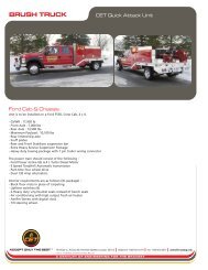
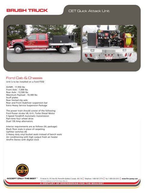
<strong>BRUSH</strong> <strong>TRUCK</strong><strong>CET</strong> Quick Attack UnitFord Cab & ChassisUnit is to be installed on a Ford F550GVWR : 17,950 lbsFront Axle : 7,000 lbsRear Axle : 13,500 lbsMaximum Payload : 10,300 lbsScuff platesRear limited slip axleRear and Front Stabilizer suspension barExtra Heavy Service Suspension PackageThe power train should consist of the following:Ford Power stroke V8, 6.4 L Turbo Diesel Motor5 Speed TorqShift Automatic transmissionPart-time four wheel driveDual 130 Amp alternatorsInterior requirements are as follows (XL package):Black floor mats in place of carpetingUpfitter switches (4)2-Heavy duty vinyl bucket seats instead of bench seatsAir conditioning with high output fresh air heaterAm/Fm Stereo with digital clockACCEPT ONLY THE BEST75 Hector St., P.O. Box 90, Pierreville (Québec) Canada J0G 1J0 Telephone: 1-800-567-2719 Fax: 1-800-434-2613 www.fire-pump.com*<strong>CET</strong> is a trademark of <strong>CET</strong> <strong>Fire</strong> <strong>Pumps</strong> Mfg Ltd.A C E N T U R Y O F E N G I N E E R I N G F O R T H E B R AV E S T
<strong>BRUSH</strong> <strong>TRUCK</strong><strong>CET</strong> Quick Attack UnitExterior requirements are as follows (XL Decor package):The chassis shall be painted by the chassis manufacturer according to the chassis manufacturer’s factory standards. The body buildershall not repaint the chassis. Cab to be Ford <strong>Fire</strong> Red (F1)Chromed front bumperNew design front lightsArgent grillDual front tow hooksMirrors, manually telescoping trailer tow with manual glass and two-way foldThe chassis exhaust system shall be extended to the rear of the right rear wheel.The tires should be a maximum traction mud / snow tireWheels to be primed greyMajor Standard Features:Two (2) front tow hooksAxle – Front Monobeam with coil spring suspensionBattery – 750 CCA 78-AHBrakes – Anti-lock System (ABS)Dual instruments panel mounted cupholdersEngine hour meterExterior cargo light – Back of cabFront and rear stabilizer barsFuel tank – 40 gallon capacityGrab handles – Driver and front passengerManual transfer case and hubs (4 x 4)Power steeringRoof clearance lightsSolar tinted glassSteering damperWindshield wipers – intervalSafety & Security:Airbag – Driver and front passengerBelt-Minder safety belt reminderBlockerBeam – includes valance air damPassenger airbag deactivation switchThe <strong>Fire</strong> Apparatus shall meet all the requirements of the NFPA 1906 standard while stationary on a grade of 10 percent in anydirection.Aftermarket Front Bumper<strong>CET</strong> <strong>Fire</strong> <strong>Pumps</strong>, Mfg. will install a customer supplied Reunel Extreme Duty Bumper / Winch / Brush guard assembly.Customer Supplied Items**The Ford Cab & Chassis and the Aftermarket front bumper will be provided by the customer and the end user will take care of allnecessary delivery arrangements to Heritage Ford in VT where <strong>CET</strong> will then take care of the remainder of the travel to its office inPierreville, Qc where production will take place.ACCEPT ONLY THE BEST75 Hector St., P.O. Box 90, Pierreville (Québec) Canada J0G 1J0 Telephone: 1-800-567-2719 Fax: 1-800-434-2613 www.fire-pump.com*<strong>CET</strong> is a trademark of <strong>CET</strong> <strong>Fire</strong> <strong>Pumps</strong> Mfg Ltd.A C E N T U R Y O F E N G I N E E R I N G F O R T H E B R AV E S T
<strong>BRUSH</strong> <strong>TRUCK</strong><strong>CET</strong> Quick Attack UnitStainless Steel Side Step BarsOne (1) set of 3" diameter stainless steel side step bars. Steps to be marine grade 304 prime stainless steel polished to a mirror finishwith molded non-slip step pad.Step area is compressed, rather than a cut out hole, to enhance strength and prevents interior corrosion.Lifetime Limited WarrantyOuter wheel insertsThe front and rear wheels shall be dressed with polished, stainless steel wheel liners, hub covers and lug nut covers. Brand to beRealwheels.Inside Doors ReflectiveAll driving and crew compartment doors shall have at least 96 in2 of reflective material affixed to the inside of each door.Engine Speed Control DeviceAn automatic engine speed control device shall be installed to allow an increase in the engine speed when the apparatus is parked.(NFPA 1906, 5.2.1.4 requirement)An interlock shall prevent the operation of this engine speed control device unless the parking brake is fully engaged and the transmissionis in neutral or park, or unless the engine speed control device is used with chassis engine driven components, in which case itshall be interlocked with the engagement of those components.Low-Voltage WarningThe condition of the low-voltage electrical system shall be monitored by a warning system that provides an visual signal to persons onthe apparatus of an impending electrical system failure caused by the excessive discharge of the battery set. An automatic engine speedcontrol device shall then increase the engine speed to the proper requested demand.A voltmeter shall be mounted on the console to allow direct observation of the system voltage.Lettering & StrippingThe finished apparatus shall be lettered to match the existing apparatus, the door logo shall be provided by the <strong>Fire</strong> Department. TheApparatus number shall be applied to each side of the chassis hood. 4” Reflective 3M stripping shall be applied on the Cab & the truckbed as per NFPA.At least 50 percent of the cab and body length on each side, at least 50 percent of the width of the rear, and at least 25 percent of thewidth of the front of the apparatus shall have the reflective material affixed to it.Deluxe Emergency lightingOne (1) 55” Super LED Whelen Lightbar, Liberty model # SLN2VLED. Lightbar to be mounted on the front top body.- 4 x Red Super LED Corners- 2 x Red Super LED Inner- 2 x White Super LED Inner- 2 x Front Facing Takedown lamps- 2 x Side Alley lamps, one (1) each side- LED Traffic Advisor integrated to the light bar with moduleMounted on front Cab & Chassis grill, Two (2) Whelen 400 series SUPER LED, red with clear lens, each with a chrome flange.Mounted each side of the chassis, Two (2) Whelen 400 series SUPER LED, one (1) each side, red with clear lens, each with a chromeflange.ACCEPT ONLY THE BEST75 Hector St., P.O. Box 90, Pierreville (Québec) Canada J0G 1J0 Telephone: 1-800-567-2719 Fax: 1-800-434-2613 www.fire-pump.com*<strong>CET</strong> is a trademark of <strong>CET</strong> <strong>Fire</strong> <strong>Pumps</strong> Mfg Ltd.A C E N T U R Y O F E N G I N E E R I N G F O R T H E B R AV E S T
<strong>BRUSH</strong> <strong>TRUCK</strong><strong>CET</strong> Quick Attack UnitMounted each side of the body, Two (2) Whelen 400 series SUPER LED, one (1) each side, red with clear lens, each with a chrome flange.Mounted in the rear lower section of the body Two (2) Whelen 400 series SUPER LED, red with clear lens driver’s side and blue withclear lens on officers side, each with a chrome flange.Wig Wag SystemOne (1) wig-wag system will be installed with a control switch on the console.Siren & SpeakerOne (1) Whelen, model # 295SLSA1, 100 watts electronic siren amplifier with PA and switch control center to be provided and installed.One (1) Whelen, model # SA315P, 100 watt speaker, to be provided and mounted on the front bumper with SAK1 universal mountingbracket.Door AjarOne (1) door ajar warning light shall be provided and installed in the consol to indicate an open body compartment door. The lightshall be properly marked with a sign “Warning Door Ajar”.Flat Bed BodyOne (1) custom <strong>Fire</strong> Application aluminum flat bed body, 110” long x 94-5/8’’ wide. The aluminum plate used in construction is .100”3003-H22 polished aluminum alloy treadplate.Body sub-frame is made from 6061-T6 aluminum tubes and channels. Sub-frame crossmembers are installed every 16”. The channelis 1-1/2” wide x 3” high x 3/16” thick. The body crossmembers shall extend the full width to support the compartment framing andshall be welded to the sub-frame main members.The Body sub-frame main members consist of 6061-T6 Aluminum square tubing of 2” wide x 6” high x 3/16” thick.The light bar will be fixed to a polypropylene tubular mount that is the same height as the cab of the truck. The uprights will be angledinward to match the aerodynamic contour of the chassis cab.The perimeter shall be made with 1/8” thick forged 3003H14 Aluminum. Forged aluminium brings a strong design that was speciallymade to embed emergency lighting & designed to fit properly a 4” reflective stripping.The body shall be attached to the chassis rails with a minimum of four (4) heavy duty “U” bolts. The body shall be separated from thechassis by 3/8” Teflon. Attachment of the body and sub-frame will allow the body to resist from all distortion and off road operationalcondition.The body is a modular design to allow removal from the chassis for major repair or mounting on a new chassis. Isolating materialbetween the body and the chassis to be installedAll welding shall be done electrically using 5356 aluminum welding wire.Flat Bed Body Cont:Rear vertical skirt will be made from 1/8” 3003-H22 polished aluminum alloy treadplate.Rear skirt to include LED Signal, brake, reverse lights, D.O.T., license plate & NFPA steps.Rear rubber mud flaps are provided. A bracket attached to the side of the muffler pipe end is installed to prevent any damaged thatcan occur to the mud flap.ACCEPT ONLY THE BEST75 Hector St., P.O. Box 90, Pierreville (Québec) Canada J0G 1J0 Telephone: 1-800-567-2719 Fax: 1-800-434-2613 www.fire-pump.com*<strong>CET</strong> is a trademark of <strong>CET</strong> <strong>Fire</strong> <strong>Pumps</strong> Mfg Ltd.A C E N T U R Y O F E N G I N E E R I N G F O R T H E B R AV E S T
<strong>BRUSH</strong> <strong>TRUCK</strong><strong>CET</strong> Quick Attack UnitTwo (2) heavy duty tow eyes shall be installed at the rear of the body (NFPA 1906 requirement). The tow eyes will be fastened directlyto each rear chassis frame rail. Hardware shall have a clear and unobstructed access.The rear of the flat bed shall have two (2) non-skid rear steps for access to pump and controls. The rear steps shall be made so it canbe folded up for use in rough terrain. All steps shall sustain a minimum static load of 500 lb (227 kg) without deformation (NFPA 1906& 1901 compliant). Stepping height from the ground to the first step shall not exceed 24”.Access handrails shall be provided where steps for climbing are located.An angle of approach and an angle of departure of at least 20 degrees shall be maintained at the front and the rear of the vehiclewhen it is loaded.CompartmentsAll compartments will be made with ½” polypropylene sheet.All compartments seams is sealed with a pliable automotive body caulking.All compartments shall have a minimum of one (1) louvered panel bolted into a wall to provide the proper airflow inside the compartment.All compartments shall be of sweep-out type with no lip at bottom edge for easy cleaning.The overlap polypropylene compartment doors shall be securely attached to the body with a full stainless steel hinge. Door openingsshall be fitted with solid neoprene weather strip completely sealing the perimeter of the compartment door opening. Lift up doorshall be installed with gas hold open struts.Each compartments will have at least one (1) 12” long clear light tube. Each light tube to have a minimum brightness of 28,000 –30,000 cd/m2 with an expected lifetime of 30,000 hrs.All compartments floors will be covered with Plastic Tiles. The tiles shall be black with yellow angled leading edges.There shall be a set of tracks for future installation of adjustable shelf(s) in each compartment. These tracks shall be installed verticallyon the walls of the compartment(s) and shall offer a multitude of height adjustment possibilities.All door lock mechanisms shall be fully enclosed within the door panels to prevent fouling of the lock in the event equipment insideinto the lock area.The compartment doors is latched with recessed, polished stainless steel ‘’D’’ ring handles and locks.R1 – L1 Transverse compartment of 13-1/2” long x 22” high x 94” transverse. Each side door to be horizontally hinged, drop downstyle with retaining cables.Custom made compartment to be designed to hold eight (8) shovels & eight (8) Rakes.R2 – L2 Two (2) 62’’ long x 30’’ high x 22’’ deep compartments behind the chassis, one (1) each side of the water tank. One (1) 12”tube light is included in each compartment, installed on top wall.R2 – L2 Two (2) Adjustable shelves to be installed, one (1) located in the driver side compartment and one (1) located in thepassenger side compartment.Under each shelf, two (2) sets of clips shall be installed to hold two (2) brush brooms under each tray.ACCEPT ONLY THE BEST75 Hector St., P.O. Box 90, Pierreville (Québec) Canada J0G 1J0 Telephone: 1-800-567-2719 Fax: 1-800-434-2613 www.fire-pump.com*<strong>CET</strong> is a trademark of <strong>CET</strong> <strong>Fire</strong> <strong>Pumps</strong> Mfg Ltd.A C E N T U R Y O F E N G I N E E R I N G F O R T H E B R AV E S T
<strong>BRUSH</strong> <strong>TRUCK</strong><strong>CET</strong> Quick Attack UnitRearOne (1) integrated to the platform compartment approximately 5’’ high x 24’’ wide x 105’’ long for suction hose storage andfolding ladders or pike poles. A flip down horizontally hinges door is furnished at the rear. The interior compartments aremade from polished 3003-H14 alloy smooth plate.Other item includedMedium Kochek Wheel Chocks with storage bracket.Electrical componentsA 12 volt electrical system is supply. The built in emergency light switch panel have a master switch plus individual switches for selective control.The switch panel is located in the cab on the driver’s side to allow for easy access. The switches on the dashboard are lighted rocker type.The wiring is secured in place, readily accessible and protected against heat, water and physical damage.Electrical harness lines shall be mechanically attached to the frame or body structure of the apparatus.The complete electrical system is separated from the chassis wiring system except for a power supply connection at chassis battery. It is alsoprotected by bolt-on type automatic circuit breakers.All wiring will be run in heat and moisture resistant plastic convoluted split loom.Electrical harness lines shall be furnished with protective looms, grommets, or other devices at each point where they pass through body panelsor structural members or wherever they lie against a sharp metal edge. A through-the-frame connector shall be permitted to be used inplace of metal protective looms or grommets.Switches, relays, terminals, and connectors shall have a direct current (dc) rating of 125 percent of maximum current for which the circuit isprotected.Conductor insulation will conform to S.A.E. requirements. All circuit are protected by automatic reset circuit breakers.All wiring furnished will conform to the national Electric Code.All circuits will be wired in conformance with S.A.E. J1292, Automobile wiring standard.All wiring will be function worded schematically.A set (2) of electric diagram will be remit upon delivery.Clearance, marker, license plate lights and reflectors will be furnished per D.O.T.LED signal, brake and reverse lights will be High Quality Grote Automotive lights recessed mount into rear aluminum skirt area of body perFMVSS 108 and CMVSS 108 requirements. Light to be Oval with chromed housing.Back Up AlarmOne (1) back-up alarm that meets the type D (97 dBa) requirements of SAEJ994 shall be provided at the rear of the apparatus. It willactivate when the transmission is placed in reverse.Rear Scene LightsTwo (2) Rear Unity scene light provided and mounted on the top of the rear water tank. One (1) to be Floodlight, one (1) to beSpotlight. Switch to be located on the light.ACCEPT ONLY THE BEST75 Hector St., P.O. Box 90, Pierreville (Québec) Canada J0G 1J0 Telephone: 1-800-567-2719 Fax: 1-800-434-2613 www.fire-pump.com*<strong>CET</strong> is a trademark of <strong>CET</strong> <strong>Fire</strong> <strong>Pumps</strong> Mfg Ltd.A C E N T U R Y O F E N G I N E E R I N G F O R T H E B R AV E S T
<strong>BRUSH</strong> <strong>TRUCK</strong><strong>CET</strong> Quick Attack UnitScene lightsTwo (2) 300W telescoping 12v scene lights mounted at the front of the Truck Bed. The light shall be single head design. One lightmounted on each side will increase visibility around the apparatus during night or light operations. Model is to be <strong>Fire</strong> ResearchFCA512-D30. Option to be installed on each light : 1- On/Off lamp head switch FCA option-ON, 2- Wire Guard FCA option-G.Compartment Lights switchesOne (1) switch per compartment shall be installed so the compartment light(s) shall come on only when compartment door is open.ConsoleOne <strong>CET</strong> aluminum fire application custom consol installed between seats with rocker switch. To be quickly identified and visible tothe driver and passenger while seated, the rocker switches shall be installed on the top face of the console designed with a 40 deg.angle. This area shall be able to hold at least two rows of rocker switch. All switches shall be rocker style internally lighted and appropriatelyidentified by panel mounted legends.The first lighted rocker switch to be a red Master Optical Warning switch. A master body disconnect automatic switch, normally opencontacts, shall be provided to disconnect all electrical loads not provided by the chassis manufacturer. The starter solenoids shall beconnected directly to the batteries.All rocker switch to have a green “On” indicator that is visible from the driver’s position shall be provided.The console will have an area to accommodate department map books, clipboards etc.. Area to be at least 13” long x 12” wide x 9”high.The console also has an area for radio head & Siren installation.Map Light, 12” gooseneck Halogen, Havis Shield, model C-MAP-S, side mounted on the cab console.All electrical components like breaker, relays, wiring etc. will be installed inside this customized consol and protected with an aluminiumbox. This consol will be design to easily gain access to those breaker, relays, wiring, etc.Controls and switches that are expected to be operated by the driver while the apparatus is in motion shall be within convenient reachfor the driver.A final layout shall be done at the pre-construction meeting.Poly Lower CompartmentsAll compartments will be made with ½” polypropylene sheet.All compartments seams is sealed with a pliable automotive body caulking.All compartments shall have a minimum of one (1) louvered panel bolted into a wall to provide the proper airflow inside the compartment.All compartments shall be of sweep-out type with no lip at bottom edge for easy cleaning.The overlap polypropylene compartment doors shall be securely attached to the body with a full stainless steel hinge. Door openingsshall be fitted with solid neoprene weather strip completely sealing the perimeter of the compartment door opening. Lift up doorshall be installed with gas hold open struts.Each compartments will have at least one (1) 12” long clear light tube. Each light tube to have a minimum brightness of 28,000 – 30,000cd/m2 with an expected lifetime of 30,000 hrs.ACCEPT ONLY THE BEST75 Hector St., P.O. Box 90, Pierreville (Québec) Canada J0G 1J0 Telephone: 1-800-567-2719 Fax: 1-800-434-2613 www.fire-pump.com*<strong>CET</strong> is a trademark of <strong>CET</strong> <strong>Fire</strong> <strong>Pumps</strong> Mfg Ltd.A C E N T U R Y O F E N G I N E E R I N G F O R T H E B R AV E S T
<strong>BRUSH</strong> <strong>TRUCK</strong><strong>CET</strong> Quick Attack UnitAll compartments floors will be covered with Plastic Tiles. The tiles shall be black with yellow angled leading edges.R1 – L1 Two (2) 24’’ long x 12’’ high x 14’’ deep compartments under body behind the chassis, one (1) each side of the truck bed.elbow located in the hosebed.Pre-connect hose traysIntegrated to the LEFT AND RIGHT side of the flat bed body, one enclosed pre-connected hose tray, each side, made from aluminiumto hold a minimum of 250’ of 1-3/4” hoseHose Trays to have a flip down doors with latches. Tray design shall allow hoses to pay out in any direction and quick hose storagewhen finished.The Hose tray shall have a 1-1/2” Pre-Connect elbow.The area shall be designed to prevent the accumulation of water and allow for ventilation to aid in drying hose in the storage area.Black Turtle Tiles to be installed and bolted on the floor.1.5" Discharge to Pre-connected Hose trayThere shall be a 1.5" valve piped from the discharge manifold to the hose tray. The valve shall be a fire grade, quarter turn drop outstyle valve with a handle and be connected to the hose tray by high pressure flexible plumbing.WATER TANKThe water tank shall be constructed of 1/2" thick polypropylene sheet stock with PolymarCo-PP resin. Water tank shall be weldedwith Heavy Duty extruded joint. The material shall be of a certified, high quality, non-corrosive, stress relieved thermo plastic, blackin colour with a textured finish, and UV stabilized for maximum protection. The skid type water tank shall be of a standard configurationand shall be so designed to have complete modular slide in capability. The unit shall incorporate transverse partitions manufacturedfor 3/8" PT2E polypropylene which shall interlock with a series of longitudinal partitions constructed of 3/8" PT2E polypropylene.All swash partitions shall be so designed to allow for maximum water and air flow between compartments and are fully welded toeach other as well as to the inside of the tank. The passenger side rear wall of the tank shall have a standard built in sight gauge 3"in width, and 70% transparent.Fill Tower & Tank CoverThe tank shall be equipped with a combination vent/overflow and manual fill tower. The fill tower shall have a 8" x 8" x 8" squarehinged type cover. The tower shall be located in the right rear corner of the tank. There shall be a vent / overflow installed inside andto the extreme rear of the tower approximately 2" down from the top. This vent / overflow shall be of a standard schedule 40polypropylene pipe with minimum ID of 3". The vent / overflow shall be piped internally toward the front and exit out the front tankwall with a 1/2" extension past the front tank wall. The tank cover shall be constructed of 1/2" thick PT2E polypropylene, black in color,UV stabilized.Tank CapacityThe tank shall have a capacity of 300 U.S. gallons of water.SumpThe floor of the tank shall be manufactured from 3/4" PT2E polypropylene. There shall be one (1) sump as standard per tank. The sumpshall be integral to the tank floor and be a minimum of 3/8" deep recessed into the floor. The sump shall not be visible from or protrudethrough the bottom of the tank.ACCEPT ONLY THE BEST75 Hector St., P.O. Box 90, Pierreville (Québec) Canada J0G 1J0 Telephone: 1-800-567-2719 Fax: 1-800-434-2613 www.fire-pump.com*<strong>CET</strong> is a trademark of <strong>CET</strong> <strong>Fire</strong> <strong>Pumps</strong> Mfg Ltd.A C E N T U R Y O F E N G I N E E R I N G F O R T H E B R AV E S T
<strong>BRUSH</strong> <strong>TRUCK</strong><strong>CET</strong> Quick Attack UnitTank OutletsThere shall be two standard tank outlets located in the same vertical plane on the driver side rear wall of the tank. One (1) 2-1/2"female NPT tank to pump suction fitting and one (1) 1-1/2" female NPT tank fill fitting with flow deflector.1" Tank DrainThere shall be a 1" tank drain to the rear side of the tank with a brass plug.Tank Mounting BlocksThe cover shall incorporate two (2) booster reel mounting blocks that shall accommodate two (2) each sliding nut fasteners. These 4"large mounting blocks shall be welded to the covers running from the rear edge of the tank forward to the front edge.Skid BaseThere shall be a full width skid base manufactured of 3/4" PT2E polypropylene welded to the tank. The pump mounting area shall besupported by ½" PT2E polypropylene gussets approximately 15" high by 32" long. The gussets shall be equipped with 2" holes to assistin lifting the unit. The mounts shall allow for the truck to be secured directly to a truck bed without the need for any skid frame workunderneath.Tank will be baffled in accordance with latest NFPA requirements.FOAM CELLA drop in style foam cell shall be provided in the tank. This foam cell shall be constructed using the same materials and methods as theskid tank. The foam tank shall be incorporated within the water tank and should be of a drop-in type integral to the water tank.FOAM CELL CAPACITYThe foam cell shall have a capacity of 10 gallons.35 CFM CAFS Diesel Powered Unit SpecificationThe CAFS provides a self-contained, diesel-powered, “slide-in” type compressed air foam system (CAFS) unit. The CAFS unit is designedto fit into the back of a standard length and width pick-up truck body.The CAFS is designed to discharge water only, air only, foam & water mixture or compressed air foam from the same discharge outlet.In addition, the consistency of the compressed air foam (expansion ratio), wet/dry is fully adjustable.EngineThe power to drive the system is provided by a Kubota, 3-cylinder, 4-cycle, Liquid-cooled diesel engine at a rating of 25 HP @ 3600 RPM.Automotive engines or ratings will not be used.**The Kubota engine shall draw its fuel from the Ford Chassis auxiliary fuel pick up on the chassis fuel tank; there shall be no need foran additional fuel tank on the unit.Water PumpThe water pump is a Model 18-MR single-stage centrifugal pump with a vertically split aluminum case with replaceable bronze impellerand seal rings on a stainless steel shaft. It is designed to provide up to 165 GPM of plain water flow and pressured up to 165 PSI withthe air compressor in the “unload” mode or load mode. The pump seal is of a mechanical design.ACCEPT ONLY THE BEST75 Hector St., P.O. Box 90, Pierreville (Québec) Canada J0G 1J0 Telephone: 1-800-567-2719 Fax: 1-800-434-2613 www.fire-pump.com*<strong>CET</strong> is a trademark of <strong>CET</strong> <strong>Fire</strong> <strong>Pumps</strong> Mfg Ltd.A C E N T U R Y O F E N G I N E E R I N G F O R T H E B R AV E S T
<strong>BRUSH</strong> <strong>TRUCK</strong><strong>CET</strong> Quick Attack UnitAir CompressorThe air compressor is of the oil injected piston type, designed and installed to supply a minimum of 35 CFM at 100 PSI of air at maximumengine RPM.The air compressor is driven by one dry Goodyear -V type belts from the engine crankshaft and is mounted to the pump platform. Theair compressor is capable of maintaining prolonged pressure from 100 to 125 pounds per square inch throughout the service life of thecomplete CAFS unit.A pneumatic modulating inlet valve mounted on the air end inlet controls the compressor.A balancing system is provided to automatically maintain the air pressure within plus-or-minus 5% of the water pump pressurethroughout the CAFS operating range.The compressor is cooled with air and the compressed air is cooled with a water cooler.The system is be capable of maintaining recommended operating temperatures throughout the full operational range in ambient temperaturesup to 115 F. A dry cartridge type air filter is provided on the compressor air intake.Foam ProportionerThe apparatus / skid unit shall be equipped with an electronic, fully automatic, variable speed, direct injection, discharge side foamproportioning system. The system shall be capable of handling Class A foam concentrate. The foam proportioning operation shall bebased on direct measurement of water flows, and remain consistent within the specified flows and pressures. System must be capableof delivering accuracy to within 3% of calibrated settings over the advertised operation range when installed according to factory standards.The system shall be equipped with a control module suitable for installation on the pump panel. Incorporated within the motordriver shall be a microprocessor that receives input from the system flowmeter, while also monitoring foam concentrate pump output,comparing values to ensure that the operator preset proportional amount of foam concentrate is injected into the discharge side ofthe fire pump. A paddlewheel-type flowmeter shall be installed in the discharge system specified to be “foam capable.”The control module shall enable the pump operator to:Activate the foam proportioning systemSelect proportioning rates from 0.1% to 1.0%See a “low concentrate” warning light flash when the foam tank runs low and in two minutes, if foam concentrate is not added tothe tank, shut the foam concentrate pump downA twelve (12) volt electric motor driven positive displacement plunger pump shall be provided. The pump capacity shall be 1.0 gpm(3.8 L/min) at 200 psi (13.8 BAR) with a maximum operating pressure up to 400 psi (27.6 BAR). The system will draw a maximum of 30amps @ 12 VDC.The motor shall be controlled by the microprocessor (mounted to the base of the pump). It shall receive signals from the control moduleand power the 1/3 hp (.25 Kw) electric motor in a variable speed duty cycle to ensure that the correct proportion of concentrate isinjected into the water stream. A full flow check valve shall be provided in the discharge piping to prevent foam contamination of firepump and water tank. A 5 psi (.35 BAR) opening pressure check valve shall be provided in concentrate line.Components of the complete proportioning system as described above shall include:Operator control modulePaddlewheel flowmeterPump and electric motor/motor driverWiring harnessesLow level tank switchACCEPT ONLY THE BEST75 Hector St., P.O. Box 90, Pierreville (Québec) Canada J0G 1J0 Telephone: 1-800-567-2719 Fax: 1-800-434-2613 www.fire-pump.com*<strong>CET</strong> is a trademark of <strong>CET</strong> <strong>Fire</strong> <strong>Pumps</strong> Mfg Ltd.A C E N T U R Y O F E N G I N E E R I N G F O R T H E B R AV E S T
<strong>BRUSH</strong> <strong>TRUCK</strong><strong>CET</strong> Quick Attack UnitDrive SystemThe water pump is directly driven. The compressor, which is mounted to the engine flywheel housing, is belt-driven using a one V-typebelt.Electrical SystemAll electrical equipment installed by the manufacturer is in conformance with current automotive electrical system standards ant therequirements of the applicable NFPA apparatus standards. The wiring is individually and permanently color and function coded.All exposed wiring runs in loom with a minimum of 280F (137.8 C) rating. All wiring loom is properly supported and attached to framemembers along the entire rum. At any point where wire or looms must pass through metal, rubber grommets are installed to protectthe wire from abrasion.The main low voltage electrical terminal block and circuit breaker panel are provided behind the pump operators panel in a locationwhich provides easy service access.The electrical connections are made using heat shrink and/or waterproof connectors. All electrical circuits are protected withautomatic reset circuit breakers or fuses.Priming SystemA Ventury type priming system is utilized. The primer is capable of priming the water pump through 20 of hard suction hose with a15 lift. Primer controls is mounted on the operators panel.Plumbing, Hoses and LinesAll piping is stainless steel. Use of grooved end pipe couplings are required for flexibility and movement of system components onmobile equipment. The compressor hoses are made of Teflon and braded with stainless steel. Hydraulic hoses are not used. Check valvesare required throughout the system to maintain integrity and shall be placed so that the air, water foam and foam solution do notinadvertently mix. Drain valves are provided on the unit to completely drain the system to prevent freeze damage.Tank to PumpThere is a 2.5” tank to pump suction fire grade valve fitted in the module and controlled from the operators panel.InletA 2.5" inlet is provided to draw water from the control panel with a 2.5” NH male connection and cap is provided.It is possible to use that line for “direct tank fill” operations with a pressurized water source.Discharge Outlet(s)There are two (2) 1.5" discharges with stainless steel plumbing to panel, mounted CAFS discharge outlets.There shall also be a 1" fire grade valve discharge for the booster reel and a 1 1/2" fire grade discharge for each of the pre-connecttrays.A Swing check valve is installed to prevent foam from back flowing into the pump.ACCEPT ONLY THE BEST75 Hector St., P.O. Box 90, Pierreville (Québec) Canada J0G 1J0 Telephone: 1-800-567-2719 Fax: 1-800-434-2613 www.fire-pump.com*<strong>CET</strong> is a trademark of <strong>CET</strong> <strong>Fire</strong> <strong>Pumps</strong> Mfg Ltd.A C E N T U R Y O F E N G I N E E R I N G F O R T H E B R AV E S T
<strong>BRUSH</strong> <strong>TRUCK</strong><strong>CET</strong> Quick Attack UnitDischarge ManifoldThere shall be a discharge manifold plumbed directly to the discharge side of the pump to incorporate discharges at the rear of theunit.This discharge manifold shall be 2" x 2" square minimum and be welded on all sides to prevent leakage. The manifold will be madefrom high quality stainless steel and painted red in color.Discharge ValvesAll valves larger than 3/4" shall be a fire service type drop out style ball valve which shall have a hard-coated anodized, high-strength,light-weight aluminum alloy body with rugged stainless steel ball and two PTFE seats.The valves shall be capable of bi-directional flow with a minimum working pressure rating of 250 psig.All stainless steel parts shall be made from 300 series material. The valves shall NOT require lubrication of the seats or any other internalwaterway component and shall be capable of swinging out of the attached waterway plumbing for easy maintenance, with theremoval of six (6) to eight (8) bolts.Any required valve 1" or smaller, unless other wise specified, shall be a standard plumbing style industrial ball valve.Tank RefillA 1” tank refill line with a 1” fire grade ball valve and a flexible, reinforced hose using internally expanded fittings to allow maximumflow.Module FrameThe frame is constructed of steel and designed for rigorous fire service. The top of the unit is hinged and allow for quick oil checks.Control PanelA laser-cut control panel is mounted to the electrical box, which is of a water resistant design. The following items are marked in a logicalmanner on the control panel to provide for simple and easy operation.1. 2-Lamp Shielded Pump Panel Light Cluster & Switch1. 2.5” Black Face, Master Water Pressure Gauge1. 2.5” Black Face, Master Air Pressure Gauge1. Primer Control1. 2.5 suction intake pressure gage.1. CAFS/Water Compressor Unload Valve1. Vernier Throttle Control1. Drain Valves1. Auxiliary Air Outlet1. System Operation Instruction PlacardACCEPT ONLY THE BEST75 Hector St., P.O. Box 90, Pierreville (Québec) Canada J0G 1J0 Telephone: 1-800-567-2719 Fax: 1-800-434-2613 www.fire-pump.com*<strong>CET</strong> is a trademark of <strong>CET</strong> <strong>Fire</strong> <strong>Pumps</strong> Mfg Ltd.A C E N T U R Y O F E N G I N E E R I N G F O R T H E B R AV E S T
<strong>BRUSH</strong> <strong>TRUCK</strong><strong>CET</strong> Quick Attack Unit1. Electrical Doora) Hour metera) Panel light switcha) Ignition switcha) FoamPro Concentrate Proportioner ControlWater Tank Indicatior<strong>Fire</strong> Research TankVision model WLA200-A00 tank indicator kit shall be installed. The kit shall include an electronic indicator module,a pressure sensor, and a 10' sensor cable. The indicator shall show the volume of water in the tank on nine (9) easy to see super brightLEDs. A wide view lens over the LEDs shall provide for a viewing angle of 180 degrees. The indicator case shall be waterproof, manufacturedof aluminum, and have a distinctive blue label.The program features shall be accessed from the front of the indicator module. The program shall support self-diagnostics capabilities,self-calibration, and a datalink to connect remote indicators. Low water warnings shall include flashing LEDs at 1/4 tank, down chasingLEDs when the tank is almost empty, and an output for an audio alarm.The indicator shall receive an input signal from an electronic pressure sensor. The sensor shall be mounted from the outside of thewater tank near the bottom. No probe shall place on the interior of the tank. Wiring shall be weather resistant and have automotivetype plug-in connectors.Location of water tank indicator shall be: Pump Panel AreaCLASS A FOAM TANK INDICATOR<strong>Fire</strong> Research TankVision model WLA260-A00 tank indicator kit shall be installed. The kit shall include an electronic indicator module,a pressure sensor, a 10' sensor cable and a tank vent. The indicator shall show the volume of Class A foam concentrate in the tank onnine (9) easy to see super bright LEDs. A wide view lens over the LEDs shall provide for a viewing angle of 180 degrees. The indicatorcase shall be waterproof, manufactured of aluminum, and have a distinctive green label.The program features shall be accessed from the front of the indicator module. The program shall support self-diagnostics capabilities,self-calibration, and a datalink to connect remote indicators. Low foam warnings shall include flashing LEDs at 1/4 tank, down chasingLEDs when the tank is almost empty, and an output for an audio alarm.The indicator shall receive an input signal from an electronic pressure sensor. The sensor shall be mounted from the outside of the foamtank near the bottom. No probe shall place on the interior of the tank. The foam tank vent shall be installed on the foam fill tower.Wiring shall be weather resistant and have automotive type plug-in connectors.Location of foam tank indicator shall be: Pump Panel AreaLabelsAll controls, inlets and discharges are clearly labeled. The labels comply with applicable NFPA standards.ACCEPT ONLY THE BEST75 Hector St., P.O. Box 90, Pierreville (Québec) Canada J0G 1J0 Telephone: 1-800-567-2719 Fax: 1-800-434-2613 www.fire-pump.com*<strong>CET</strong> is a trademark of <strong>CET</strong> <strong>Fire</strong> <strong>Pumps</strong> Mfg Ltd.A C E N T U R Y O F E N G I N E E R I N G F O R T H E B R AV E S T
<strong>BRUSH</strong> <strong>TRUCK</strong><strong>CET</strong> Quick Attack UnitTestingThe competed unit shall undergo a manufacturers run-in test prior to delivery. The engine, pump and air compressor are operated fora minimum period of one day, during which time the test operator will monitor and record the functions and performance of each systemcomponent. Compressed air foam is produced during the test.This testing will be performed to ensure proper system operation and performance prior to shipment. The manufacturer provides writtencertifications that the tested unit meets all performance criteria contained herein (NFPA). Water flow performance is measuredusing standard fire department test methods.ManualsOne (1) copy of the Operation and Maintenance Manual and a CD copy are provided to the purchaser with each unit. This manualincludes detailed instructions in the operation and maintenance of the overall unit, engine, water pump, air compressor and foampumpPerformanceWater PumpAir CompressorEngine Horsepower165GPM @ 20 PSI35 CFM @ 105 PSI25 HP @ 3600 RPMWarrantyEngineCompressorWater PumpChemical Injector2 year1 year2 years / 2000 hours1 yearAll fabrication and materials are warranted for a period of two (2) years barring accidents, abuse or negligence. Excluded from thewarranty are all consumables and parts subject to routine replacement. We will repair or assist in the repair or replacement of theproduct in its entirety.1 1/2" NSTM WATER ONLY DISCHARGE VALVE ON CAFS SYSTEMThere shall be a 1 1/2" fire service type drop out style ball valve with 1 1/2" NSTM threads, cap and chain which shall have a hard-coatedanodized, high-strength, light-weight aluminum alloy body with rugged stainless steel ball and two PTFE seats.The valve shall be capable of bi-directional flow with a minimum working pressure rating of 250 psig.All stainless steel parts shall be made from 300 series material. The valves shall NOT require lubrication of the seats or any other internalwaterway component and shall be capable of swinging out of the attached waterway plumbing for easy maintenance, with theremoval of six (6) to eight (8) bolts.This valve shall be feed from the pump head in a manner so to NOT allow the induction of foam and/or air into its plumbing allowingit to maintain the fullest of it pumping capacity as restricted by the size of the pump / engine combination and not being restricted bythe foam system limitiations in plain water flow.This valve shall be capable of clean water pumping operations simotanious to the discharging of CAFS through the other manifoldeddischarges as specified.This valve shall be operated at the pump panel with in easy reach of the operater and be clearly labeled as a "WATER ONLY" discharge.ACCEPT ONLY THE BEST75 Hector St., P.O. Box 90, Pierreville (Québec) Canada J0G 1J0 Telephone: 1-800-567-2719 Fax: 1-800-434-2613 www.fire-pump.com*<strong>CET</strong> is a trademark of <strong>CET</strong> <strong>Fire</strong> <strong>Pumps</strong> Mfg Ltd.A C E N T U R Y O F E N G I N E E R I N G F O R T H E B R AV E S T
<strong>BRUSH</strong> <strong>TRUCK</strong><strong>CET</strong> Quick Attack UnitBOOSTER REEL12v ELECTRIC REWIND BOOSTER REELA Hannay 12v electric rewind booster reel capable of handling a customer specified amount of booster hose shall be supplied andinstalled on the officers side rear of the flatbed. The hose reel shall be protected against power shortage.The reel shall have a push button rewind control and a backup geared crank rewind handle.The reel shall be equipped with a 1" NPT 90 degree swivel inlet, and a 1" NST outlet riser.The reels discs and drum shall be manufactured of steel and be red in color.BOOSTER REEL ROLLERSOne (1) high mounted roller and spool assembly shall be furnished and installed on the booster reel.The roller assembly shall be located on the rear of the reel to facilitate deployment of the hose.200' OF 1" NST FABRIC COVERED BOOSTER HOSEThe booster reel shall be equipped with 200' of 1" NST fabric covered booster hose.The hose shall be single jacketed made of 100% polyester construction, with helical reinforcement, and red ENCAP treatment.Minimum service test pressure of 300 PSIG (2100 kPa).Minimum proof test pressure of 600 PSIG (4200 kPa).Minimum straight burst test pressure of 1800 PSIG (12600 kPa).Rear Hitch for Trailer ConnectionA rear mounted Class III trailer hitch shall be securely attached to the chassis frame and shall include the 7-pin wiring trailer harness.Manufacturer’s DiscretionMaterials, parts or procedures used are subject to change at the manufacturer's discretion at any time during the production of theunit described with in these specifications to provide equal or better products with the written consent of the end user.Complete apparatus built accordingly to NFPA 1906 & DOT Compliant.ACCEPT ONLY THE BEST75 Hector St., P.O. Box 90, Pierreville (Québec) Canada J0G 1J0 Telephone: 1-800-567-2719 Fax: 1-800-434-2613 www.fire-pump.com*<strong>CET</strong> is a trademark of <strong>CET</strong> <strong>Fire</strong> <strong>Pumps</strong> Mfg Ltd.A C E N T U R Y O F E N G I N E E R I N G F O R T H E B R AV E S T
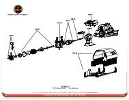
<strong>BRUSH</strong> <strong>TRUCK</strong>Technical DrawingACCEPT ONLY THE BEST75 Hector St., P.O. Box 90, Pierreville (Québec) Canada J0G 1J0 Telephone: 1-800-567-2719 Fax: 1-800-434-2613 www.fire-pump.com*<strong>CET</strong> is a trademark of <strong>CET</strong> <strong>Fire</strong> <strong>Pumps</strong> Mfg Ltd.A C E N T U R Y O F E N G I N E E R I N G F O R T H E B R AV E S T