Advantages of FPGA-Based Multiprocessor Systems in Industrial ...
Advantages of FPGA-Based Multiprocessor Systems in Industrial ...
Advantages of FPGA-Based Multiprocessor Systems in Industrial ...

You also want an ePaper? Increase the reach of your titles
YUMPU automatically turns print PDFs into web optimized ePapers that Google loves.
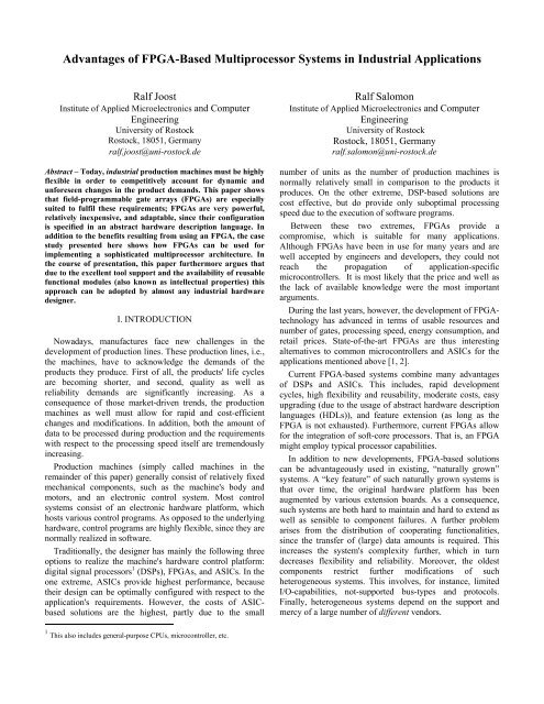
This paper argues and shows that <strong>FPGA</strong>s can at leastrelieve some <strong>of</strong> the design problems discussed above. To thisend, Section II briefly surveys the possibilities andadvantages <strong>of</strong> those <strong>FPGA</strong>s. A short <strong>in</strong>troduction to thesimple and easy use <strong>of</strong> s<strong>of</strong>t-core processors will be given.As Section III describes, <strong>FPGA</strong>s today have grown <strong>in</strong> sizesuch that they can even realize one or even several custommadeprocessor cores.In order to show the potential benefits, Section IVdescribes an <strong>in</strong>dustrial case study <strong>in</strong> the area <strong>of</strong> cutt<strong>in</strong>g-edge<strong>of</strong>fset pr<strong>in</strong>t<strong>in</strong>g. S<strong>in</strong>ce the entire system has been growndur<strong>in</strong>g several years, it exhibits some limitations, which alsoh<strong>in</strong>der future developments. In order to expand to newfrontiers, this section also proposes a new architecture, whichis based on a multiprocessor platform.Section V reports on a prototypical implementation, whichcan be seen as a pro<strong>of</strong>-<strong>of</strong>-concept. The section also discussesthe required resource consumption as well as other technicaldetails. F<strong>in</strong>ally Section V and VI f<strong>in</strong>ish this paper with acritical discussion and the conclusion respectively.II. BACKGROUND ON <strong>FPGA</strong>SFirst commercial <strong>FPGA</strong>’s were released by XILINX <strong>in</strong> themiddle <strong>of</strong> the 80’s <strong>of</strong> the last century. At those times, deviceswere small, slow, and quite expensive. The first XILINXdevice XC2064 had 1200 gates. Today, <strong>FPGA</strong>’s <strong>of</strong>fermillions <strong>of</strong> system gates and operate at a speed <strong>of</strong> up to300 MHz. S<strong>in</strong>ce the price <strong>of</strong> currently available <strong>FPGA</strong>s startsbelow 10 US$, many manufactures use them even for endproducts, such as mobile phones, network solutions, andmultimedia devices.Even factory automation applications might pr<strong>of</strong>it from thegood performance-to-cost 2 ratio <strong>of</strong> modern <strong>FPGA</strong>s. Here,<strong>FPGA</strong>s are <strong>of</strong> particular <strong>in</strong>terest, because a small number <strong>of</strong>production systems require significant development efforts.Us<strong>in</strong>g <strong>FPGA</strong>s <strong>in</strong> the design process has the follow<strong>in</strong>g threedistict advantages. First, most <strong>FPGA</strong>-vendors support thedesign and development process by provid<strong>in</strong>g powerful andeasy-to-use electronic design tools (EDA), excellentdocumentation, and personal support. Second, demonstrationexamples do not <strong>in</strong>volve high manufactur<strong>in</strong>g costs as wouldbe usual with ASICs. Third, modifications and adjustmentscan be implemented at any stage <strong>of</strong> the design process andeven “<strong>in</strong> the field”. Advanced systems extent the latter po<strong>in</strong>teven further <strong>in</strong> that they allow the dynamic reconfiguration<strong>of</strong> the runn<strong>in</strong>g hardware. Such systems are subject <strong>of</strong> currentresearch efforts, also known as dynamically reconfigurablehardware [10]. This approach receives recent attention,because it allows for multiply re-us<strong>in</strong>g valuable resources.<strong>FPGA</strong>s have grown <strong>in</strong> size that much that they allow forthe s<strong>of</strong>t-implementation <strong>of</strong> processor cores, which might alsobe a DSP-core. Thus, a design challenge is to decide, which2 In this context, “cost” refers not only to the actual <strong>FPGA</strong> but also torequired tools, design efforts, ma<strong>in</strong>tenance, etc.parts <strong>of</strong> the system, i.e., functionalities, are to beimplemented directly <strong>in</strong> hardware gates or processed bys<strong>of</strong>tware, which runs <strong>in</strong>side the <strong>FPGA</strong>s s<strong>of</strong>t core. State-<strong>of</strong>the-artEDA-tools, such as ALTERA's system-on-aprogrammable-chip(SOPC) Builder and XILINX’Embedded Development Kit (EDK), simplify this parallelhardware-s<strong>of</strong>tware co-design process dramatically. This isaccomplished by automatically recogniz<strong>in</strong>g all hardwarecomponents and provid<strong>in</strong>g s<strong>of</strong>tware access methods forthem. Also, the development tools solve the address andresource management automatically on the fly (see alsoSection IV.C).Furthermore, the developer can resort to many ready-tousecomponents, also called <strong>in</strong>tellectual properties (IP), suchas network-Interfaces, video controllers, memory controllers,and so forth. The usage <strong>of</strong> IP-cores reduces the developmentefforts and thus may help reduce costs.III. SOFT-CORES AND MULTIPROCESSOR SYSTEMSAs mentioned above, <strong>FPGA</strong>s <strong>of</strong>fer the possibility <strong>of</strong><strong>in</strong>corporat<strong>in</strong>g s<strong>of</strong>t-cores. S<strong>of</strong>t-core processors can beconsidered as equivalents to a microcontroller or “computeron a chip”. They comb<strong>in</strong>e a CPU, peripherals, and memoryon a s<strong>in</strong>gle chip. They also provide access beyond the actual<strong>FPGA</strong> chip through <strong>in</strong>tegrated standard or custom-made<strong>in</strong>terfaces. Some available reduced <strong>in</strong>struction set computer(RISC) architectures are [3, 4, 5]:1. NIOS and NIOS II CPUs from ALTERA ,2. LEON2 and LEON3 CPUs from Gaisler Research,3. and the Microblaze CPU from XILINX.Some <strong>of</strong> the currently available <strong>FPGA</strong>s allow for therealization <strong>of</strong> several processors simultaneously. As is wellknown, multiprocessor systems are a proper method to<strong>in</strong>crease system performance and to concentrate process<strong>in</strong>gelements <strong>in</strong> one <strong>FPGA</strong>. S<strong>in</strong>ce multiprocessor systems aresupported by the EDA tools, the system generation can becompleted with<strong>in</strong> a couple <strong>of</strong> days. Generally, most vendorssupport multiprocessor systems by provid<strong>in</strong>g dedicatedhardware constructs, such as mutexes, to synchronizedaccesses to shared resources. For a general <strong>in</strong>troduction tomultiprocessor systems, the <strong>in</strong>terested reader is referred tothe pert<strong>in</strong>ent literature [7].IV. INDUSTRIAL CASE STUDYThis section presents an <strong>in</strong>dustrial case study. This<strong>in</strong>cludes a description <strong>of</strong> the exist<strong>in</strong>g system, the discussion<strong>of</strong> the problems and goals, and the presentation <strong>of</strong> aprototypical implementation.A. The Exist<strong>in</strong>g SystemIn 1993, basysPr<strong>in</strong>t Ltd. <strong>in</strong>troduced a technology calledComputer To conventional Plate (CTcP) for the exposure
<strong>of</strong> pr<strong>in</strong>t<strong>in</strong>g plates for the <strong>of</strong>fset pr<strong>in</strong>t<strong>in</strong>g process [12]. Adist<strong>in</strong>ct feature <strong>of</strong> the CTcP technology is that it allows forus<strong>in</strong>g ultraviolet-light-sensitive pr<strong>in</strong>t<strong>in</strong>g plates, which, <strong>in</strong>comparison to laser light exposition used by most othercompetitors, results <strong>in</strong> significant cost reductions because <strong>of</strong>lower acquisition and disposal charges. Fig. 1 shows anexample <strong>of</strong> a CTcP solution available from basysPr<strong>in</strong>t.synchronizes the image updat<strong>in</strong>g with the exposure head’smovement. The PC transfers the appropriate image data via aLAN-connection to the exposure head prior to the imag<strong>in</strong>g <strong>of</strong>each stripe. In addition the control-PC also has to handlevarious other control signals. For the system’s functionality,it is very important to ensure a precise coord<strong>in</strong>ation <strong>of</strong> headmovements and data tim<strong>in</strong>gs, because even a s<strong>in</strong>glemalfunction spoils the entire plate.exposure headbear<strong>in</strong>gpr<strong>in</strong>t<strong>in</strong>g plateplate holderterm<strong>in</strong>alFig. 1: A CTcP system, called UV-SetterControl-PCLAN Trigger-Card Interbuswire drag cha<strong>in</strong>motorX-axisencoderX-axisfocusadjustmentcontrolmotorY-axisencoderX-axiscoolercontrolimage process<strong>in</strong>gsystemCTRLInterfacelightn<strong>in</strong>gcontrolLANInterfaceThe very first version <strong>of</strong> the CTcP process exposed thepr<strong>in</strong>t<strong>in</strong>g plate <strong>in</strong> a so-called step-and-repeat mode. The imagewas divided <strong>in</strong>to tiles, which were transferred and processedseparately. A tile consists <strong>of</strong> up to 1280 by 1024 pixels. Eachtile covers an area <strong>of</strong> approximately 4 cm². It might beimportant to note that the process<strong>in</strong>g, i.e., expos<strong>in</strong>g thepr<strong>in</strong>t<strong>in</strong>g plate, <strong>of</strong> each tile requires the exact compliance <strong>of</strong>pre-def<strong>in</strong>ed exposure times. After a tile is f<strong>in</strong>ished, theexposure head advances to the next position. Dur<strong>in</strong>g themovement <strong>of</strong> the exposure head, no <strong>in</strong>formation istransferred to the plate, thus <strong>in</strong>creas<strong>in</strong>g the time required toexpose the whole plate. Due to this disadvantage, basysPr<strong>in</strong>tdeveloped a cont<strong>in</strong>uous expos<strong>in</strong>g process, called scroll<strong>in</strong>gmode. This process divides an image <strong>in</strong>to adjacent stripes,with each consist<strong>in</strong>g <strong>of</strong> an entire row <strong>of</strong> the aforementionedtiles. Furthermore, when process<strong>in</strong>g a stripe, the exposurehead is mov<strong>in</strong>g with constant speed.Due to cost reasons, the new system architecture isrealized by several modifications and add-ons <strong>of</strong> the oldarchitecture. In other words, the current system architectureis the result <strong>of</strong> a rather evolutionary development process.Such an evolutionary development process is the regularcase, but clearly results <strong>in</strong> some limitations, which arediscussed <strong>in</strong> detail <strong>in</strong> Section IV.B.Fig. 2 presents a simplified schematic <strong>of</strong> the electricalcontrol system. All grey-shaded elements symbolizecomponents, which are mov<strong>in</strong>g over the plate’s surfacedur<strong>in</strong>g the image process<strong>in</strong>g procedure. The two motorsmove the exposure head, also called image process<strong>in</strong>gsystem, to the desired position. The two encoders feed the<strong>in</strong>formation about the current position back to the triggercard,which is <strong>in</strong>stalled <strong>in</strong> the control PC. The trigger-cardFig. 2: Schematic <strong>of</strong> a pr<strong>in</strong>t<strong>in</strong>g plate process<strong>in</strong>g systemB. Problems and GoalsThe current system architecture suffers from the follow<strong>in</strong>gfour limitations. First <strong>of</strong> all, it employs a large number <strong>of</strong>electrical wires for transmitt<strong>in</strong>g all the required data, such asimage data, motor position<strong>in</strong>g <strong>in</strong>formation, signals for focusadjustment, as well as various other control signals. Thesewires are embedded <strong>in</strong> a drag cha<strong>in</strong> (connection betweenfixed body parts and the mov<strong>in</strong>g exposure head). From amechanical eng<strong>in</strong>eer<strong>in</strong>g po<strong>in</strong>t <strong>of</strong> view, the large number <strong>of</strong>wires is a severe problem, because the drag cha<strong>in</strong> requires asubstantial amount <strong>of</strong> the mach<strong>in</strong>e’s rare space. The usage <strong>of</strong>a second exposure head makes this situation even worse,s<strong>in</strong>ce it requires an additional set <strong>of</strong> transfer and controlwires.The second issue is given by the spatial distribution <strong>of</strong> datasources and s<strong>in</strong>ks. This requires rather long wires and, as aconsequence, significant efforts with respect to signalstability and reliability, connectors, as well as test<strong>in</strong>g andma<strong>in</strong>tenance.The third topic to address consists <strong>of</strong> the large variety <strong>of</strong>communication protocols. S<strong>in</strong>ce each connection has slightlydifferent tim<strong>in</strong>g parameters, further system extensions arehard to realize, or nearly impossible.The fourth limitation concerns the <strong>in</strong>corporation <strong>of</strong> a newprocess<strong>in</strong>g scheme, which is currently under development atbasysPr<strong>in</strong>t. This new scheme tries to avoid mechanical<strong>in</strong>terruptions and thus detrimental vibrations by a rathercont<strong>in</strong>uous expos<strong>in</strong>g process.
Control-PCLAN Interbuswire drag cha<strong>in</strong>motorX-axisencoderX-axismotorY-axisencoderX-axisfocusadjustmentcontrolimage process<strong>in</strong>gsystemcoolercontrolTriggerlogicCTRLInterfaceNIOS IIMPSoClightn<strong>in</strong>gcontrolLANInterfacelocalmemCore 0masterNIOS II (f)peripheral<strong>in</strong>terfacelocalmemCore 1slaveNIOS II (s)LAN<strong>in</strong>terfacelocalmemCore 2slaveNIOS II (s)avalon switch fabricfocus<strong>in</strong>terfacemotor<strong>in</strong>terfacesharedmemorymemory<strong>in</strong>terfacetrigger<strong>in</strong>terfaceFig. 3: Schematic <strong>of</strong> the modified systemAs a consequence <strong>of</strong> the issues discussed above,basysPr<strong>in</strong>t, <strong>in</strong> cooperation with the University <strong>of</strong> Rostock, isredesign<strong>in</strong>g the entire electrical system 3 . In so do<strong>in</strong>g, itpursues the follow<strong>in</strong>g goals:1. Significantly reduc<strong>in</strong>g the total number <strong>of</strong> all dataand control wires.2. Aim<strong>in</strong>g at a compact system design, i.e., manycomponents at only a few places, <strong>in</strong> order to reducethe number <strong>of</strong> cables, connectors, and potentialsources <strong>of</strong> failures.3. Concentration <strong>of</strong> functionalities locally <strong>in</strong> order toavoid permanent data-transfers and to reduce thenumber <strong>of</strong> required bus protocols.The follow<strong>in</strong>g subsection presents a system design thataccounts for the problems and goals discussed above.C. An <strong>FPGA</strong>-<strong>Based</strong> <strong>Multiprocessor</strong> ArchitectureThe new architecture, as shown <strong>in</strong> Fig. 3, is based on aprogrammable <strong>FPGA</strong>-device. The ma<strong>in</strong> part <strong>of</strong> the newsystem is a NIOS II-based multiprocessor architecture, which– among other advantages – allows for scalability on demandand loosely coupled system designs. For an <strong>in</strong>-depthdiscussion <strong>of</strong> the advantages and disadvantages <strong>of</strong>multiprocessor architectures, the <strong>in</strong>terested reader is referredto [7]. The chosen <strong>FPGA</strong> conta<strong>in</strong>s the multiprocessor systemon a chip (MPSoC) and the trigger-logic, formerly <strong>in</strong>stalled<strong>in</strong> the host-PC, as well. To ensure the system’s proper tim<strong>in</strong>gbehavior, i.e., the timely coord<strong>in</strong>ation <strong>of</strong> the motormovements, trigger events, and supply <strong>of</strong> image data, theMPSoC <strong>in</strong>cludes one processor-core only for manag<strong>in</strong>g thetime-critical operations. This approach significantly relaxesthe mutual dependencies, and thus limitations, between theexposure system and the host. S<strong>in</strong>ce the trigger-logic resides<strong>in</strong>side the <strong>FPGA</strong>, it also shortens the communication paths,and thus reduc<strong>in</strong>g the requirements and structures for signalpropagation on the fly.3 In other cooperation with the University <strong>of</strong> Rostock, basysPr<strong>in</strong>t is alsoredesign<strong>in</strong>g other system parts.cooler,control-PCfocus adjustmentcontrol-PCmotorFig. 4: Components <strong>of</strong> the NIOSII-MPSoCtriggerlogicIn case basysPr<strong>in</strong>t succeeds <strong>in</strong> the development <strong>of</strong> newexpos<strong>in</strong>g processes, the trigger-logic has to be properlyadapted. The new logic will replace the old trigger-logicalready implemented <strong>in</strong> the system.This approach, as compared to the exist<strong>in</strong>g system, has thefollow<strong>in</strong>g dist<strong>in</strong>ct advantage: Any modification <strong>of</strong> thetrigger-logic does not have any side-effects on the systemboard,as long as the external <strong>in</strong>terfaces <strong>of</strong> the trigger-logicrema<strong>in</strong> fixed. Any new download <strong>of</strong> a hardwareconfiguration file <strong>in</strong>to the <strong>FPGA</strong> affects only the <strong>in</strong>ternallogic-elements <strong>of</strong> the <strong>FPGA</strong>.The structure <strong>of</strong> the MPSoC proposed <strong>in</strong> this paper is anasymmetric shared memory architecture as all cores haveaccess to the external memory device shown <strong>in</strong> Fig. 4. Thisenables communication between the various processor coresvia globally accessible memory constructs. S<strong>in</strong>ce accesses tothe shared memory are realized by simple load and storeoperations, it significantly simplifies communication efforts;i.e., this approach does not require any particular overhead,such as message queues, queue ma<strong>in</strong>tenance, or messageprocess<strong>in</strong>g.The utilization <strong>of</strong> shared memory also allows dynamicchanges <strong>in</strong> the executed s<strong>of</strong>tware environment. For example,depend<strong>in</strong>g on the currently used pr<strong>in</strong>t<strong>in</strong>g plate type, core 0can receive parameters or entire s<strong>of</strong>tware segments byutiliz<strong>in</strong>g the LAN-Interface. After send<strong>in</strong>g a notification, adifferent processor, e.g., core 1, can access the very samedata without any further copy<strong>in</strong>g or process<strong>in</strong>g operations.In that way, the flexibility for different purposes is <strong>in</strong>creasedas the system can adapt to various other plate types, whichhave vary<strong>in</strong>g characteristics and thus require slightmodifications <strong>in</strong> the expos<strong>in</strong>g process.As can be seen <strong>in</strong> Fig. 4, all components are coord<strong>in</strong>ated <strong>in</strong>the follow<strong>in</strong>g way: Core 0, labelled “master”, is responsiblefor ma<strong>in</strong>ta<strong>in</strong><strong>in</strong>g status <strong>in</strong>formation and manag<strong>in</strong>g datatransfer to and from the host-PC. It also controls execution <strong>of</strong>the two slave-cores, 1 and 2. The first slave processes allmovement data generated by the attached trigger-logic. The
second slave-core operates as a peripheral controllersupport<strong>in</strong>g <strong>in</strong>tegrated system features, such as the focusadjustment, the cooler, and various other auxiliarycomponents.The MPSoC itself is created mostly by custom elementsfrom ALTERA’s system libraries. Only a few systemspecific<strong>in</strong>terfaces for focus control, motor-connection, andtrigger-logic have to be designed by the developer. But eventhis work is supported by the ALTERA tools. Therefore, thedesign efforts for build<strong>in</strong>g <strong>in</strong>terfaces are held at its m<strong>in</strong>imum.The system shown <strong>in</strong> Fig. 4 represents an expandableplatform. Whenever the addition <strong>of</strong> further functionalitiesexceeds the current computational capabilities, the developermay solve this problem by add<strong>in</strong>g another CPU. This way,the system performance can be adapted to any requirements.Especially time-restricted operations pr<strong>of</strong>it from thisapproach.A. MethodsV. IMPLEMENTATIONThe development discussed <strong>in</strong> this paper concentrates onthe ALTERA NIOS development kit Cyclone Edition [11].It features a Cyclone <strong>FPGA</strong> EP1C20 with approximately20,000 programmable logic elements. The developmentboard is equipped with a wide range <strong>of</strong> useful peripherals,such as 16MB SDRAM, 8MB flash-memory, an onboardEthernet device, and several I/O-<strong>in</strong>terfaces.The Cyclone <strong>FPGA</strong> <strong>of</strong>fers 300 configurable user I/Op<strong>in</strong>s,which accomplishes the application at hand. The pricefor such a device starts at approximately 100 US$ per devicefor a 24-device tray. Depend<strong>in</strong>g on the ordered volume, theprice may be as low as 25 US$ per device.As mentioned above, this research resorts on theconfigurable NIOS II CPU. “Configurable” <strong>in</strong> the context <strong>of</strong>the NIOS II CPU means that features, such as <strong>in</strong>terfaces, onchip memories, watchdogs, and timers, can be freely addedor removed. It is furthermore possible to augment the CPU’sarithmetic logical unit (ALU) with dedicated hardware forspecial purposes, such as video- or audio-process<strong>in</strong>g. Thisadditional ALU-hardware is called “custom <strong>in</strong>struction”.From the s<strong>of</strong>tware-perspective, custom <strong>in</strong>structions appear asmach<strong>in</strong>e-generated assembly macros or C functions [3]. Thisapproach yields significant performance improvements, s<strong>in</strong>ces<strong>of</strong>tware functionalities can be transferred to physicalhardware. A m<strong>in</strong>imal configuration <strong>of</strong> a NIOS II processorconsumes between 700 and 1800 logic elements and runs at aclock speed <strong>of</strong> up to 200 MHz.ALTERA provides special hardware mutexes to simplifyaccesses to components shared by more than one processor.Such mutex performs an atomic test-and-set operation, <strong>in</strong>order to avoid concurrent memory access by two or moreprocessors.The creation <strong>of</strong> the processor system has been done withthe help <strong>of</strong> ALTERA’s SOPC-Builder. It provides agraphical user <strong>in</strong>terface, which <strong>in</strong>stantiates system featuresand handles both address and <strong>in</strong>terrupt management. Formore detailed <strong>in</strong>formation about ALTERAs SOPC-Builder,the <strong>in</strong>terested reader is referred to the literature [6].B. First Results and Critical DiscussionThe first pro<strong>of</strong>-<strong>of</strong>-concept implementation <strong>in</strong> the ALERACyclone <strong>FPGA</strong> takes about 9,000 logic elements, which isapproximately 45% <strong>of</strong> the overall logic-resources. The clockgeneration is realized by the two onboard phase locked loops(PLL). In order to keep compilation time at a m<strong>in</strong>imum, thecore speed was set to 50 MHz and no optimizationconstra<strong>in</strong>ts were established dur<strong>in</strong>g the development stage.When switch<strong>in</strong>g to the f<strong>in</strong>al release, the system will beoptimized <strong>in</strong> order to ga<strong>in</strong> higher clock rates, with anexpectation <strong>of</strong> approximately 80 MHz.The current development version already achieves thedesired goals mentioned <strong>in</strong> Section IV; the aggregation <strong>of</strong> thetrigger-logic and process<strong>in</strong>g elements <strong>in</strong>to an embeddedsystem allows for shorter communication paths, reduced thenumber <strong>of</strong> separated system units, and made many <strong>of</strong> thewires connected to the host-PC dispensable. On a short term,this approach yields cost and ma<strong>in</strong>tenance improvements. Ona long term, this modifiable adaptable platform is open t<strong>of</strong>urther improvements and also provides enough resources foradditional features.While fulfill<strong>in</strong>g the given requirements, the prototypicalimplementation po<strong>in</strong>ts to some issues, which are subject tocurrent as well as future research. First <strong>of</strong> all, the centralsystem bus, which handles all the <strong>in</strong>terprocessorcommunications, might turn <strong>in</strong>to a bottleneck. This potentialproblem should be appropriately addressed by both hardwareand s<strong>of</strong>tware designs. Current research is devoted to thedevelopment <strong>of</strong> simple and adaptable solutions [8, 9]. Theprototype described <strong>in</strong> this paper uses the Avalon switchfabric for <strong>in</strong>terprocessor communication purposes. Inaddition, the Avalon switch fabric improves the performanceby its ability to support multiple bus masters. In theapplication at hand, it is possible to map s<strong>of</strong>tware tasks ontoseparate CPUs, i.e., rather distributed than parallelprocess<strong>in</strong>g, <strong>in</strong>terprocessor communication is not a severeissue; other application pr<strong>of</strong>iles might require differentcommunication mechanisms, such as message pass<strong>in</strong>g [7].VI. FUTURE WORKThe current implementation is a prototype that represents apro<strong>of</strong>-<strong>of</strong>-concept. Future research will be devoted to thedevelopment <strong>of</strong> a complete platform, which will be convertedto a production system by basysPr<strong>in</strong>t. The rema<strong>in</strong>der <strong>of</strong> thissection sketches the most important hardware and s<strong>of</strong>twareissues.On the hardware side, the current VHDL code <strong>of</strong> theexist<strong>in</strong>g multiprocessor platform is to be enhanced by all therequired <strong>in</strong>terfaces. This <strong>in</strong>cludes a LAN-connection for
transferr<strong>in</strong>g image data, <strong>in</strong>terfac<strong>in</strong>g the peripherals, such ascooler, motors, and other auxiliary hardware, and connect<strong>in</strong>ga CAN bus. Another major part consists <strong>of</strong> the <strong>in</strong>tegration <strong>of</strong>the exist<strong>in</strong>g trigger-logic functionality.On the s<strong>of</strong>tware side, the next steps are as follows: First <strong>of</strong>all, the exist<strong>in</strong>g s<strong>of</strong>tware functionalities have to be ported tothe new system. Then, the distribution <strong>of</strong> the data andcommunication objects, i.e., the memory map, should beoptimized with respect to the system’s runtime behavior.After the completion <strong>of</strong> the steps mentioned above, a f<strong>in</strong>alfield study has to prove both sufficient process<strong>in</strong>g speed andfulfilment <strong>of</strong> the required tim<strong>in</strong>g behavior.VII. CONCLUSIONThis paper has presented the benefits <strong>of</strong> utiliz<strong>in</strong>g an <strong>FPGA</strong>to implement a multiprocessor platform for an <strong>in</strong>dustrialapplication <strong>in</strong> the field <strong>of</strong> <strong>of</strong>fset pr<strong>in</strong>t<strong>in</strong>g. This paper hasfurthermore shown that <strong>FPGA</strong>-based solutions enable theusage <strong>of</strong> s<strong>of</strong>t-core processors, which leads to flexible,scalable, and easy-to-ma<strong>in</strong>ta<strong>in</strong> systems.For the follow<strong>in</strong>g reasons, the approach presented heremight be <strong>of</strong> particular <strong>in</strong>terests for <strong>in</strong>dustrial applications: Itenables the efficient participation <strong>of</strong> future trends, such asdynamically reconfigurable hardware [10]; the support bypowerful tools, the usage <strong>of</strong> an abstract hardware descriptionlanguage, and the option <strong>of</strong> employ<strong>in</strong>g IP-cores all result <strong>in</strong>significant time and money sav<strong>in</strong>gs; s<strong>in</strong>ce the particularsystem is not bound to a particular <strong>FPGA</strong>, i.e., the hardwarecan be ported to a different <strong>FPGA</strong> by a simple recompilation,it can be easily scaled if demands desire so.Another po<strong>in</strong>t to consider, when work<strong>in</strong>g with <strong>FPGA</strong>s, isthat hardware description, i.e., the VHDL code, rema<strong>in</strong>s atthe development side and can furthermore not be recoveredby third parties by read<strong>in</strong>g the configuration file. That is, allsystem-related <strong>in</strong>formation can be kept confidential. Thisalso reduces time and money costs dur<strong>in</strong>g communication tothird-party companies.All the advantages described above are a strong argumentfor us<strong>in</strong>g <strong>FPGA</strong>s <strong>in</strong> <strong>in</strong>dustrial applications. Another equallyimportant argument is that all the provided tools allow almostany developer to utilize <strong>FPGA</strong>s at very low personal andmonetary costs.VIII. ACKNOWLEDGMENTSThe authors gratefully thank Dr. Horst Steppat, manag<strong>in</strong>gdirector at basysPr<strong>in</strong>t, and John Hedde, director <strong>of</strong> researchand development at basysPr<strong>in</strong>t, for provid<strong>in</strong>g the exist<strong>in</strong>gtechnology and the excellent cooperation. In addition theauthors s<strong>in</strong>cerely thank Jens Hildebrandt, former member <strong>of</strong>this research and now with Siemens VDO Automotive AG.This research was supported <strong>in</strong> part by the German federalm<strong>in</strong>istry <strong>of</strong> education and research, grant number 03i4919B.IX. REFERENCES[1] Chris Wright and Mike Arens, “<strong>FPGA</strong>-based Systemon-ModuleApproach Cuts Time to Market, AvoidsObsolescence”, <strong>FPGA</strong> and Programmable LogicJournal, Volume VI, No. 6, Feb. 2005[2] Salil Raje, “Catch<strong>in</strong>g the <strong>FPGA</strong> Productivity Wave”,Electronic Design, Oct. 2004, Onl<strong>in</strong>e ID 8931[3] Altera Corp., NIOS II Processor Reference Handbook,Altera Document NII5V1-1.2, Altera Corp., San Jose,CA, Jan. 2005[4] Gaisler Resarch, LEON2 Processor User’s Manual –XST Edition, Gaisler Research AB, Goteborg, Sweden,Jan. 2005[5] XILINX Inc., MicroBlaze Processor Reference Guide,XILINX Document UG081 (v5.0), XILINX Inc., SanJose, CA, Jan. 2005[6] Altera Corp., Quartus II Handbook Volume 4 - SOPC-Builder, Altera Document QII5V4-1.0, Altera Corp.,San Jose, CA, Feb. 2005[7] David. E. Culler and Jasw<strong>in</strong>der Pal S<strong>in</strong>gh, ParallelComputer Architecture – A Hardware/S<strong>of</strong>twareApproach, Morgan Kaufmann Publishers, Inc., SanFrancisco, California, 1999[8] José Carlos Palma, Al<strong>in</strong>e Vieira del Melo, FernandoGehm Moraes, Ney Calanzans, “Core CommunicationInterface for <strong>FPGA</strong>s”, 15 th Symposium on IntegratedCircuits and System Design, Porto Allegre, Brazil, 2002[9] Ross B. Ortega and Gaetano Borriello, “CommunicationSynthesis for Distributed Embedded <strong>Systems</strong>,” <strong>in</strong>Proceed<strong>in</strong>gs <strong>of</strong> the 1998 IEEE/ACM <strong>in</strong>ternationalconference on Computer-aided design, pp. 437-444,1998[10] Re<strong>in</strong>er Hartenste<strong>in</strong>, “The Microprocessor is no moreGeneral Purpose: why Future Reconfigurable Platformswill w<strong>in</strong>,” <strong>in</strong> Proceed<strong>in</strong>gs <strong>of</strong> the Second Annual IEEEInternational Conference on Innovative <strong>Systems</strong> <strong>in</strong>Silicon, 1997[11] Altera Corp., Nios Development Board ReferenceManual, Cyclone Edition, Altera Document MNL-N2DEVLBDCYC-1.1, Altera Corp., San Jose, CA,[12] basysPr<strong>in</strong>t, UV-Setters Series 7, basysPr<strong>in</strong>t Ltd., 2004