

model 102 portable ftir instruction manual - D&P Instruments ...
model 102 portable ftir instruction manual - D&P Instruments ...
model 102 portable ftir instruction manual - D&P Instruments ...

Create successful ePaper yourself
Turn your PDF publications into a flip-book with our unique Google optimized e-Paper software.
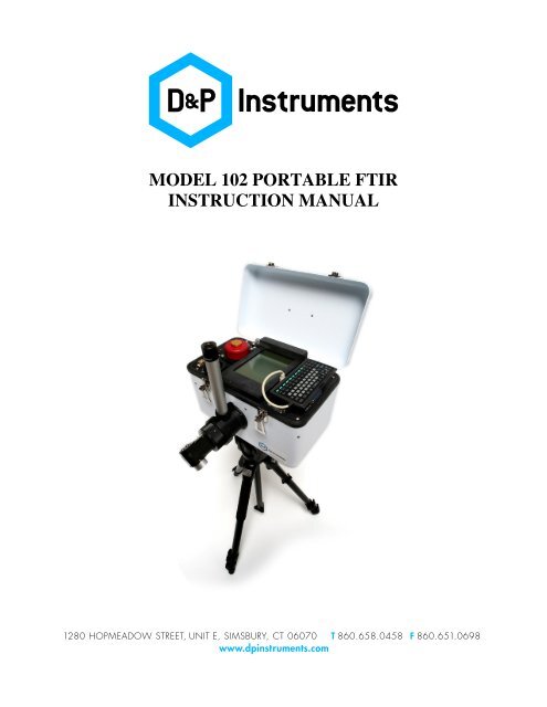
MODEL <strong>102</strong> PORTABLE FTIRINSTRUCTION MANUAL
D&P <strong>Instruments</strong> Model <strong>102</strong> Win2K Instruction Manual Ver 1.2 May 2006Table of ContentsSystem Description ......................................................................................................................... 3Optical Subsystem .......................................................................................................................... 3Electronic Subsystem...................................................................................................................... 4Temperature Alarms ................................................................................................................... 5Computer Subsystem ...................................................................................................................... 6Software Operation ......................................................................................................................... 7File Menu........................................................................................................................................ 8File Dialog Box........................................................................................................................... 8Menu Selections.......................................................................................................................... 8Instrument Menu........................................................................................................................... 10Display Menu................................................................................................................................ 11Process Menu................................................................................................................................ 13Menu Selections........................................................................................................................ 13Help Menu .................................................................................................................................... 15Function Keys ............................................................................................................................... 16Measuring Emissivity ................................................................................................................... 19Getting Data Off ........................................................................................................................... 20Shipping Procedure....................................................................................................................... 20System Specifications ................................................................................................................... 21Troubleshooting ............................................................................................................................ 21General...................................................................................................................................... 21System Computer...................................................................................................................... 23General Tips for using the Model <strong>102</strong> Spectrometer.................................................................... 24General...................................................................................................................................... 24Emissivity Measurement........................................................................................................... 25<strong>102</strong>F Setup Diagram ..................................................................................................................... 262
D&P <strong>Instruments</strong> Model <strong>102</strong> Win2K Instruction Manual Ver 1.2 May 2006System DescriptionThe Model <strong>102</strong> Portable Field Spectrometer is a complete person-<strong>portable</strong> infraredspectrometer packaged in a small case. It includes a miniature Michelson interferometer, withinput optics and infrared detector, drive and sampling electronics, and embedded PC typecomputer. Software is supplied to acquire, process, and store spectra on an internal hard disk. AUSB memory device or LAN connection can be used to transfer data to another computer. Thesoftware is controlled via a miniature keyboard, with all data displayed on a built-in miniature6.4" diagonal monochrome LCD screen. The screen is a transflective type, optimized to be bothlow power and sunlight readable. A switched backlight is included with the LCD screen for useindoors. If desired, any PS/2 type keyboard can be substituted for the miniature one and anexternal VGA monitor can be used in parallel with the internal LCD.The entire instrument is ruggedized and sealed from the environment, allowing its use inthe harsh conditions in the field. Operation from AC, battery, or automobile cigarette lighter ispossible. Internal power use has been minimized to give the longest time on battery power. Thescreen will blink when it is being updated, and the temperatures and time will change. There isalso a rotating bar in the lower right corner of the screen that moves when the CPU is active.A worldwide AC supply is standard equipment, and allows prolonged use where AC isavailable. The power cable for the system is a standard cigarette lighter plug, which facilitatesoperation from an automobile cigarette lighter socket. The input voltage is displayed on aminiature digital voltmeter on the main panel. The operating voltage range of the instrument is10.8 to 13.2 volts DC, with positive on the center terminal of the power cord. The maximumcurrent draw is about 6 amps when all functions are drawing maximum power. The nominalcurrent is more like 1-2 amps, including the computer and scan. When asleep, the system drawsless than 1 amp.Optical SubsystemThe core of the spectrometer is the Michelson interferometer. This contains infraredoptics, beam splitter, and a scanning mirror assembly. Input light passes through the fore optics,an aperture, and a lens (which also seals the unit) into the interferometer. The internal mirrors areservo driven at a constant speed, producing the interference patterns. The output light passesthrough a focusing lens (which also seals the unit) onto an infrared detector in a liquid nitrogen(LN 2 ) dewar. The standard detector is a dual sandwich type, consisting of Indium Antimonide(InSb) over Mercury Cadmium Telluride (HgCdTe, or MCT). This detector has a spectral rangeof approximately 2 to 16 micrometers. This must be filled with liquid nitrogen before use, usingthe funnel provided. Be very careful when filling the detector, and always wear gloves and eyeprotection. The best technique is to put in about three funnels, then let the detector cool for awhile. It will eventually spout a plume of vapor as the internal Dewar surface is finally cooled to77 degrees K. After that, more liquid nitrogen must be added to fill the tank nearly to the top. Iftoo much LN 2 is added initially, the Dewar may spout liquid nitrogen and spray it up out of thefilling hole. Do not put any exposed body parts near the detector fill hole when filling thedetector. Severe frostbite can result!A temperature controlled laser diode (LD) provides the reference for the servo andsampling electronics, and wavelength calibration for the spectrum. The temperature set point foreach laser diode is internal, and is preset at the factory. Since the temperature of this laser3
D&P <strong>Instruments</strong> Model <strong>102</strong> Win2K Instruction Manual Ver 1.2 May 2006determines its wavelength, sufficient time must be allowed after powering the unit for thiscontroller to reach its set point. This is indicated by an LED labeled “LD” on the control panel,and is usually 1-5 minutes. The LED will be red if heating the LD, green if cooling it. It shouldbe dim or extinguished when the set point is reached.The detachable fore optics are used to aim the instrument at a target visually, and directtarget energy into the input of the interferometer. It is a two piece assembly, having a separateeyepiece assembly and rotating input optic. The standard input optic is 1 inch in diameter, with a4.8 degree field of view. This gives a 3-inch diameter spot at about 3 feet away. An optional 2-inch diameter input optic can be used, which has a 2.4 degree field of view. There are multiplepositions of these input optics for viewer focusing. The first stop is used for close range, which isgood for most tripod work, looking at the ground. The other stops, further in, are focused fromabout 10 feet to infinity. The input optic snout can also be used for aiming by rotating it. To viewa target, the small lever in the base of the eyepiece assembly is pulled up to provide “through thelens” viewing of the target. To take data, the lever should be dropped down. This directs theinput through to the spectrometer.Electronic SubsystemThe electronic subsystem consists of a set of two printed circuit boards. One drives thescanning mirrors in the interferometer and derives control signals used throughout the system.The other performs detector signal conditioning, interface to the analog to digital converter, andthree temperature control functions. Power is provided both directly by the input source and froman internal power supply contained in the computer subsystem.The servo function drives the interferometer at a constant speed, using the laser channelof the interferometer signal as a reference. This same laser channel provides a sampling signalfor the infrared detector channel. There are two BNC outputs on the panel for monitoringpurposes:“LAS” provides the laser signal, an 8-10 volt peak to peak clipped sine wave at about 5 kHz“DET” brings out the infrared detector signal, a burst of around +/- 1-2 volts at zero optical pathdifference (OPD) once per scan, or about once per second, normally.These are good diagnostics for troubleshooting, but are not used otherwise. There arevarious LED indicators on the panel, located underneath, and shaded by, the mini-keyboard.They are arranged in two sets; one set contains four LEDS (3 green, 1 red) and the other set hasthree bicolor LED’s. Between the sets of LED’s is a pushbutton switch, called “BOOST”. Thefunctions of the LED’s and switch are as follows:“DG” (green) flashes on during data transfer, off in between“SCAN” (green) turns on when scan power is applied“STBY” (green) indicates standby and computer power, no scan on“ERROR” (red) indicates a problem with the laser signalThe only input to the servo function is the “BOOST” push button. This is used when theservo cannot start the scan, usually in cold conditions. This is indicated by the red “ERR” LED.This should not be applied for more than 10 seconds, as it may overheat the drive electronics:4
D&P <strong>Instruments</strong> Model <strong>102</strong> Win2K Instruction Manual Ver 1.2 May 2006“BOOST”(pushbutton) applies full power to the servo to get it startedThe second set of LED’s indicate the state of the three temperature controllers in thesystem. They are two-color type LED’s. Green indicates the controller is cooling, red indicateswarming. The brightness indicates how hard the controller is driving the temperature. When thetemperature set point is reached, the LED will become dimmer and flicker a little. Off means thecontroller is not operating.“INST” (bicolor) green means the instrument is being cooled, red means warm“BB” (bicolor) green means the blackbody is being cooled, red means warm“LD” (bicolor) green means the laser diode is being cooled, red means warmThere are three temperature control loops in the instrument. One controls the laser diode(LD) temperature, maintaining it at a precise internal set point, which then holds the laserreference wavelength at a precise value. This will come on for a time when power is first appliedto the instrument. No data should be acquired while the LD is being driven to its set point, as itwould be uncalibrated in wavelength.A second loop controls the temperature of the interferometer, which aids in maintaining aprecise calibration as the ambient temperature changes. This temperature controller is initiallyturned on and set automatically to the temperature at turn-on of the instrument. The set point canbe changed by the user, or the controller turned on and off, under the Instrument-Temperaturesoftware menu. A change in set point may become necessary if the ambient temperature changesdramatically during an extended acquisition period. Re-setting the temperature may require astabilization time of up to 30 minutes. It should be noted here that the temperature control has aneasier time heating than cooling. For this reason, the instrument temperature should never beallowed to get below 5 degrees C of the ambient temperature. This condition could cause thecontroller to overheat, possibly damaging the electronics. Generally, if very high (above 35 C) orvery low (below 15 C) temperatures are expected during measurement, it is best to preheat thesystem for an hour or more before taking it out. The set point chosen should be 1 or 2 degreesabove the highest expected temperature of the measurement period.The third temperature control loop is for the stabilized blackbody accessory. This deviceconnects externally, and is used to calibrate certain kinds of measurements. The set point andon/off control for this is also done in software, under the Instrument-Temperature softwaremenu. The three temperatures of these controllers, and a fourth ambient temperature sensorlocated inside the enclosure, are read out in a status line at the bottom of the screen. They arealso stored with the data.Temperature AlarmsThere is a temperature monitoring function in the software that will warn of certaintemperatures in the system being out of range. This will be evidenced by an audible alarm andflashing messages on the screen. The F9 key silences the alarm. There are three alarmconditions:1.) The instrument temperature control is on, and the instrument temperature is different fromthe set point by the tolerance set under Factory Setup (F10). The recommended settingis 5 degrees. Any larger can result in damage to internal electronics;5
D&P <strong>Instruments</strong> Model <strong>102</strong> Win2K Instruction Manual Ver 1.2 May 20062.) The instrument temperature is beyond the limits set under Factory Setup (F10). Theinstrument is designed to run between 15 and 35 degrees C;3.) The ambient air temperature inside the instrument enclosure is beyond the limits set underFactory Setup (F10). The air temperature for normal operation should always bebetween 5 and 40 degrees C. Otherwise, components can be damaged.The user should make all attempts to correct the alarm condition. The alarm for theinstrument set point condition can be fixed by resetting the instrument temperature set point.This is done in the Instrument-Temperature software menu function. This will then require sometime to equilibrate. It may also involve bringing the instrument to a warmer or coolerenvironment for a while. At the very least, all attempts should be made to complete datacollection as soon as possible. Pressing F9 will turn off the audible alarm, but the on screenflashing messages will continue until the alarm condition is fixed. The alarms for instrument andambient temperature limits have a built in hysteresis of two degrees C. Therefore, the instrumenttemperature must be brought up to 2 degrees above the lower alarm point, or down to 2 degreesbelow the upper alarm point to de-activate that alarm. Similarly, the ambient air temperaturewould have to be brought up to 2 degrees above the lower alarm point, or down to 2 degreesbelow the upper alarm point to de-activate that alarm.Computer SubsystemThe computer subsystem is built up from modules conforming to the PC/104 bussstandard. Three modules are used: 1.) Hi efficiency 50 watt power supply; 2.) CPU, video, andperipherals; 3.) Analog and Digital Input/Output (I/O). The power supply for the computersubsystem is used to power the entire electronic package as well. The CPU module contains allthe functions of a PC type computer, including video (CRT and LCD), RAM, hard and floppydisk, keyboard, mouse, serial, parallel, USB, LAN, and external VGA. A hard disk drive ismounted to this assembly. The LCD display is a standard 640 X 480 pixel monochrome VGAtype. The I/O board has 16 channels of 16 bit analog input, four channels of 12 bit analog output,and eight each digital inputs and outputs.The field keyboard is a miniature 11.3” X 5.5” unit with 88 keys. This is sufficient to runall software functions. It can be replaced with any PS/2 type keyboard. The mouse supplied withthe system is a standard nine pin serial mouse. No mouse is required to run, but one can be usedif desired. A standard VGA monitor can be connected to the VGA port on the panel. A printercan be connected to the parallel port for hard copy. The USB or LAN port is used to get data offusing any USB memory device.The only external control for the computer is a “COMPUTER RESET” switch, which is arecessed pushbutton type located next to the mouse connector, under the mini-keyboard. This isused to reboot the computer if it becomes hung up at any time. It is not used under normalcircumstances. There is a backup CMOS battery and speaker located under the panel. Thebackup battery is for time and date only, and needs changing about every 5 years. A lithium 3.6volt type is required.6
D&P <strong>Instruments</strong> Model <strong>102</strong> Win2K Instruction Manual Ver 1.2 May 2006Both raw and processed data can be exported as ASCII text files or .SPC files, so it canbe imported to other applications for further processing and/or display. The ASCII fileextensions all end in X. There are eleven types of exported files:Sample (.SAX)Reference (.REX)Warm Blackbody (.WBX)Cold Blackbody (.CBX)Downwelling Radiance (.DWX)Ratio (.RTX)Difference (.DIX)Inverse (.INX)Absorbance (.ABX)Radiance (.RAX)Emissivity (.EMX)raw sampleraw referenceraw warm blackbodyraw cold blackbodyraw downwelling radianceprocessed ratio SAM/REFprocessed difference SAM-REFprocessed inverse 1-SAM/REFprocessed absorbance -log (SAM/REF)processed radianceprocessed emissivityThe .SPC files all end in .SPCFile MenuThe File menu has 9 items in its submenu, selected by mouse, arrow key, or underlinedletter. They are:Open Save As Save Settings Data File Name and DirectoryAutoName Reverse Video AutoCalibrate A-to-D Print ExitFile Dialog BoxSome of entries under File, and elsewhere in the software, refer to bringing up a “FileDialog Box”. Its appearance and operation are explained here. There are four sections in thisbox. Moving between sections can be done with the mouse or, if the keyboard is being used, theTAB key (to move forward) or TAB key (to move backward). To move within a section,the mouse or cursor key is used. The first section of this dialog box contains the directoriesavailable. The second section of this box lists various files in the current directory. They may beselected and traversed as desired. The third section will contain the file selected. The fourthsection lists the currently active mask for file extensions. Once a file is highlighted, the Enter keyselects it into the Filename box, and it can be opened or saved to by then selecting OK.Menu SelectionsFile-Open first brings up a small dialog box containing the valid file types, as determinedby the current settings for the Math function under Process. For all Math functions exceptRadiance and Emissivity, the choices are Sample or Reference. For Radiance, the choices areCBB (Cold Blackbody), WBB (Warm Blackbody), or Sample. For Emissivity, the choices arethe same as Radiance, with the addition of DWR (Down-welling Radiance) type files. Once afile type is selected, the File Dialog Box appears, with the mask for the file type selected. Allfiles of that type in the current directory will be displayed in the center of the file dialog box.8
D&P <strong>Instruments</strong> Model <strong>102</strong> Win2K Instruction Manual Ver 1.2 May 2006Any annotation saved with the file, and selected header information, is printed in the bottom ofthe window. The operation of the File Dialog Box is explained at the beginning of this section.File-Save As works very much like Open, bringing up a small dialog box to choose a filetype to save under, again having selections that depend on the Math selected under Process. Forall Math functions except Radiance and Emissivity, the choices are Sample or Reference. ForRadiance, the choices are CBB (Cold Blackbody), WBB (Warm Blackbody), or Sample. ForEmissivity, the choices are the same as Radiance, with the addition of DWR (Down-wellingRadiance) type files. Once a file type is selected, a dialog box appears for an annotation to beadded to the data in the file. A line of text can be added in the long text box, or CANCEL willbypass the annotation and bring up the File Dialog Box, with the mask set for the file typeselected previously. All files currently stored in the current directory with that mask will bedisplayed in the center section of the File Dialog Box. One of these can be used, or a new nametyped in. The operation of the File Dialog Box is explained at the beginning of this section.Save Settings has no submenu. It is used simply to save the current instrument settingsinto the default setup file WINFT.INI, which is loaded when the program starts. It has the sameeffect as the “Save Settings and Exit” when leaving the program, but does so without exiting.Data File Name and Directory brings up a File Dialog Box. This is used to create andspecify directories for data to be read from and stored to. A name entered in the File name boxwill be used as the base name for the Autoname function.AutoName controls the automatic file naming function. When turned on, this willautomatically generate sequential filenames when taking large data sets quickly. When this menuitem is selected, a submenu appears containing a dialog box for entering a root name, a selectionto Activate (Off or On), and OK, CANCEL. A dot appears next to Off or On to indicate whetherAutoname is enabled or disabled. A root name can be entered in the space provided. If Autonameis enabled, a three-digit number will be appended to that root name and files will be saved withauto-incrementing numbers. The appropriate three-character extension for the data type beingsaved will be added to the filename. File types (i.e. SAM and REF) can be mixed within a givenroot name, and annotation can be added at the time of saving the file. A prompt will appear at thetime of the file save indicating the filename and extension used.The Reverse Video function switches the display from white on black to black on white.This is needed when an external display is connected, because the internal LCD displays videothat is the opposite of normal. It is a toggle function.AutoCalibrate A-to-D does a <strong>manual</strong> autocalibration of the analog to digital converter inthe system. This function brings up a dialog box explaining that this takes 30-60 seconds. Asecond dialog box reports the results afterwards.Print will bring up a standard Windows printing dialog box, then print the screencontents. A printer must be connected and installed into Windows prior to running this function.Exit will terminate the program, but will first prompt the user whether to save currentinstrument settings into the WINFT.INI file, or exit without saving. The same action can beinvoked with the X keystroke combination.9
D&P <strong>Instruments</strong> Model <strong>102</strong> Win2K Instruction Manual Ver 1.2 May 2006Instrument MenuThe Instrument menu has 5 items in its submenu, selected by mouse, arrow key, orunderlined letter. They are:Coadds Resolution Zero Fill FFT Apodization TemperaturesMenu SelectionsCoadds sets the number of spectra to be averaged into a coadded spectrum. Noise can bereduced by the square root of the number of coadds. Coadding takes extra time in dataacquisition, and also results in larger data files, since all interferograms are saved to allowreprocessing at a later time. Selecting this brings up a small dialog box. The present number ofcoadds is displayed in a box. To change the number, select the box with mouse or cursor arrowkeys and type the new value followed by Enter. Valid numbers are in the range of 1-100.Selecting OK sets the new value; Cancel retains the old value.Resolution is used to specify the size of the FFT performed, and thus the resolution ofthe resulting spectrum. The number of points collected is not changed, and all interferogram datais stored in the raw data file, so any spectrum can be reprocessed later at a different resolution.Selecting this item brings up a dialog box with the choices for resolution (in cm -1 ) on the left,with the current setting indicated with a dot. Clicking on any other setting with the mouse, ormoving there with the arrow keys and hitting Enter will change the selection. On the right side isthe OK, CANCEL selection. If this setting is changed, an automatic recalculation of all relevantspectra will be performed.Zero Fill is used to generate higher plot resolution at any spectral resolution. The rawFFT resolution in some cases can be quite coarse, and yield poor lineshape. By zero filling theinterferogram to a larger FFT size, more points are generated in the FFT, giving better lineshapeand smoother plots. The maximum FFT size in the instrument is 32,768 points. The scan lengthdetermines the maximum spectral resolution. The choices shown under this menu are:None no zero filling2X interferogram filled out with two times the number of points4X interferogram filled out with four times the number of points8X interferogram filled out with eight times the number of pointsIf this setting is changed, an automatic recalculation of all relevant spectra will beperformed.FFT Apodization sets the weighting function to be used to window the interferogram databefore performing the FFT. Selecting this item brings up a dialog box with a list of 6 possiblefunctions. The currently selected function is marked with a dot. The choices listed are:None10
D&P <strong>Instruments</strong> Model <strong>102</strong> Win2K Instruction Manual Ver 1.2 May 2006TriangleHanningHammingBlackmanGaussianIn general, the apodization to be used depends on whether it is more important tosuppress noise or see sharp features. Going from the top of the table to the bottom, the sharpnessdecreases, while the noise suppression increases. Since all interferograms are saved, theapodization can be changed on data in memory or on stored files, and the spectrum recomputed.If this setting is changed, an automatic recalculation of all relevant spectra will be performed.Temperatures is where all instrument and blackbody temperatures are set, and theirrespective controllers can be turned on and off <strong>manual</strong>ly. When this item is selected, a dialog boxis displayed. At the top of this box, there are three entries for blackbody set points, all in degreesC. The topmost entry (Manual BB Set Point) is for <strong>manual</strong> control of the blackbody from thisscreen. After setting a temperature here, the blackbody must be turned on, using the BB on/offcontrol in this dialog box. The next two entries (AutoCalibrate Cold BB and AutoCalibrateWarm BB) are for the Cold and Warm set points for the blackbody in the automatic calibrationsequence, which is explained under the Process menu description, Calibrate function. These arethe set points that will be used in the calibration sequence of cold, then warm blackbody. Theyare entered here to avoid having to specify them each time a calibration is done.Below the three blackbody set points is the Instrument Set Point. This is the set point forthe instrument temperature controller. It is initially set at the current instrument temperaturewhen the system is turned on. It may be reset <strong>manual</strong>ly at any time. To change any of these setpoints, use the mouse or Tab keys to select it, and type the new value, followed by Enter. Thenew value should appear in place of the old.Below the set points are two on/off controls. One is for instrument control, the other for<strong>manual</strong> blackbody (BB) control. The current state of each control has the dot filled in. The initialsettings are Instrument control ON, Blackbody control OFF. To change these, use the mouse, oruse the Tab key to select the control, then the cursor key to change it to a new setting. All newsettings will take effect when Enter is pressed, or the OK button is activated. Selecting Cancelwill reload the previous settings.Display MenuThe Display menu has 3 items in its submenu, selected by mouse, arrow key, orunderlined letter. They are:Plot Type Display Units Plot ScalesMenu SelectionsPlot Type specifies what type of display to use for data. The choices are:Interferogramdisplays the interferogram full screen in one window11
D&P <strong>Instruments</strong> Model <strong>102</strong> Win2K Instruction Manual Ver 1.2 May 2006SpectrumBothdisplays the spectrum full screen in one windowdisplays the interferogram in one window at the top of the screen,and the spectrum in a separate window at the bottom of the screen.Selecting this item brings up a dialog box with three choices. The current selection willbe marked with a dot. To change the plot type, use the mouse to click on it, or cursor keys plusEnter to select a new setting. The submenu closes, and the existing data will be re-plotted. Ifthere is no data, no replot will be done.Display Units is used to set the X and Y axis units for all displays. There are threechoices for the X units:Micrometers The X scale is displayed and exported in micrometers (um)Nanometers The X scale is displayed and exported in nanometers (nm)Wavenumbers The X scale is displayed and exported in wavenumbers (cm -1 )It should be noted that the X, or wavelength, scale is not linear, i.e. having unequal deltaX values. Any plot or further processing of ASCII exported data should use the wavelength scaleincluded in the X, Y data.The Y units are those for raw data only. Processed data is either dimensionless orexpressed in calibrated units of physical properties. At present, there is only one choice for rawdata units:Volts per FFT componentThe Y scale is detector volts per spectral element.The currently selected units for each axis are marked with a dot. To change units, click onthe new setting with the mouse, or use the arrow keys or Tab to highlight the new choice. Thedot will indicate the new selection. Then choose OK to finish the process, and the new scaleswill take effect. Choose Cancel to leave without changing the units.Display Scales is used to set the display limits for interferogram and spectral plots. Whenthis item is activated, a dialog box appears to select Spectrum or Interferogram scales to set.Choosing one of these brings up another dialog box containing settings for the X scale and Yscale. For the X scale, a low and high limit can be set, or there is a choice for All X points to bedisplayed. These are mutually exclusive choices. When displaying a plot, the F8 function keycan be used to toggle between All X and the <strong>manual</strong> limits set here. For the Y scale, a low andhigh limit can be set, or Auto scaling. These, too, are mutually exclusive choices. Whendisplaying a plot, the F9 function key can be used to toggle between Y-axis auto scaling and the<strong>manual</strong> limits set here. Once the limits are set up, choosing OK sets the new limits, or Cancelleaves them unchanged. It should be noted here that the <strong>manual</strong> scale settings are altered whenusing the cursor arrow keys to zoom and pan on a plot being displayed. To get back to specific<strong>manual</strong> scale settings, this screen will have to be used.12
D&P <strong>Instruments</strong> Model <strong>102</strong> Win2K Instruction Manual Ver 1.2 May 2006Process MenuThe Process menu normally has 1 item in its submenu, selected by mouse, arrow key, orunderlined letter. If Radiance or Emissivity math is selected, a second item to calibrate a sampleappears. Once a sample has been calibrated, a third item to fit a Planck function to a calibratedradiance appears. If a Planck function has been fitted to a calibrated radiance, a fourth menu itemappears to remove the Planck function. The four functions are:Math (Calibrate Instrument) (Fit Planck to Radiance) (Remove Planck Plot)Menu SelectionsMath is used to set which math, if any, is to be done on acquired or restored data files.The choice of Math function also determines what types of data will be acquired or restoredwhen any of those functions are used. When the Math item is selected, a dialog box appears witha choice of none, or six different math operations. They are:Noneno math performed, raw data displayedRatio Sam/Ref the Sample file is divided by the Reference fileDifference Sam-Ref the Reference file is subtracted from the Sample fileDifference Ref-Sam the Sample file is subtracted from the Reference fileInverse 1-Sam/Ref the ratio function is subtracted from 1Absorbance -log (Sam/Ref) the logarithm of the ratio is calculated and negatedRadiance f (cbb,wbb,sam) calibrated Radiance in (Watts/(m 2 *microns*sr))Emissivity f (cbb,wbb,dwr,sam) a calibrated radiance is corrected for sky reflectedenergy and divided by a Planck at the estimatedsample temperatureThe current math function being used will be indicated with a filled in dot when the Mathfunction is selected. To change the function, click on the new one with the mouse, or arrow to itand press Enter. The menu will close, and, if the data is available, the plot with the new functionwill be calculated and displayed. To leave the Math function without changing anything, pressESC or Cancel.Calibrate Instrument appears under the Process menu if either Radiance or Emissivityis chosen as the Math function. This operation requires two blackbody data files (a Cold and aWarm) to be acquired or restored. The calibration function generates a slope and offsetcorrection at each wavelength, which is then used to take out the instrument function whendisplaying sample Radiance or Emissivity. The units of Radiance will be in [Watts/m 2 *um*sr].The generation or regeneration of these corrections takes place automatically whenever anyblackbody is acquired or restored. At least one Cold and one Warm blackbody are needed for avalid calibration. As soon as one of each is loaded, the calibration function is generated. This isindicated by the “Instrument Calibrated” message in the lower left part of the status line at thebottom of the screen. Subsequent acquisition or restoring of any blackbody data willautomatically trigger a re-calibration to occur. The calibration will be valid even if other mathfunctions are selected and other types of data collected.13
D&P <strong>Instruments</strong> Model <strong>102</strong> Win2K Instruction Manual Ver 1.2 May 2006Selecting this menu item brings up a submenu with three choices:Acquire Data and CalibrateOpen BB Files and CalibrateCalibrate Now with Open Data Filesto acquire new BB datato restore previously acquired BB datato use current data in memorySelecting the first option, Acquire Data and Calibrate, will open a dialog box for theAutocalibrate function. From this screen, the instrument’s blackbody can be controlled, dataacquired, and instrument calibration performed. There are 5 choices on this screen:Set Cold BBSet Warm BBAcquireBB OffClose(X)selects the cold setting for blackbody, highlighted if selectedselects the warm setting for blackbody, highlighted if selectedacquires the cold or warm blackbody data when at temperatureused to turn the blackbody controller off after collecting datacloses the Autocalibrate screenThe Set Cold BB and Set Warm BB choices each have the current set point for eachprinted underneath the selection box. These are preset by the user under the Instrument-Temperature menu item. The Acquire box has a note under it as to the current state of the BBcontrol. It will indicate whether the BB control is Off, or display the set point when Cold orWarm is selected. BB Off is used to <strong>manual</strong>ly turn off the blackbody after all data has beencollected. The instrument calibration will be updated automatically after a new BB file is loadedor acquired, even if the Math function is changed.Once the choice of cold or warm blackbody has been made, the blackbody will be turnedon and start slewing to the set point. It may take a few minutes for the blackbody to reach the setpoint. The actual blackbody temperature is indicated on the status display at the bottom of thescreen as “Tbb”. When it has stabilized at the new set point, the acquisition can be started.Activating the Acquire function brings up a second dialog box for the actual acquisition of thedata. The instrument scan will be turned on, then acquire the number of coadds presently set,then prompt for the data to be saved or not. Saving will bring up the File Dialog box, describedunder the File Menu description. After that, control returns back to the Autocalibrate screen.From there, blackbody data can be taken or re-taken, the blackbody turned off, or theAutocalibrate screen can be closed.Selecting the second option, Open BB Files and Calibrate, will open the File Dialogbox, which is described under the File Menu description. Using the File Dialog box, choices aremade for a stored Cold, then Warm blackbody files. These are loaded into memory one at timeand displayed, the instrument is re-calibrated, and the menu closed. The display will show theWarm blackbody spectrum.Selecting the third option, Calibrate Now with Open Data Files, uses the current Coldand Warm blackbody data in memory to generate the instrument calibration. This is generallyused after Cold and Warm blackbody data has been acquired or restored <strong>manual</strong>ly from theAcquire or Restore functions. This function is somewhat redundant, as the new calibration isgenerated automatically when BB data is acquired or restored.Fit Planck to Radiance appears under the Process menu only if three operations havebeen performed:14
D&P <strong>Instruments</strong> Model <strong>102</strong> Win2K Instruction Manual Ver 1.2 May 2006The Math function is set to RadianceThe instrument has been calibrated with Cold and Warm blackbodiesA sample has been acquired or restoredThis function is used to fit a Planck function to a Calibrated Radiance spectrum. Onceselected, a dialog box appears to set the temperature to be used for the Planck. There are twochoices for setting the Planck temperature:Manual-Input Planck TemperatureAuto-Fit Planck Temperatureallows user to set Planck temperature <strong>manual</strong>lyfits the Planck to the Calibrated RadianceFor the <strong>manual</strong> input, a dialog box appears where a Planck temperature can be entered indegrees C as XX.X. A temperature can be typed into the prompt on the screen, followed byEnter. Activating the Compute function computes the Planck at the specified temperature andoverlays it on the Calibrated Radiance spectrum. For this computation, the Planck emissivity isset to 1.0. The current Planck temperature is displayed in the upper left corner of the screen whenthis function is active. The Cancel box terminates the Planck Fit function.The Auto-Fit function brings up a dialog box in which a wavelength interval, and aknown emissivity value within that interval, can be specified. To continue, the lower and upperwavelengths of the interval are entered in their respective blocks, each followed by the Tab key.The Emissivity Value in that interval is typed into its box. Selecting Compute will then try tomatch the Planck function to the present Calibrated Radiance, in the interval specified. ThatPlanck will be overlaid on the Calibrated sample radiance to show how good the fit is. This canbe performed repeatedly and alternately with the <strong>manual</strong> fit to optimize the Planck fit to theCalibrated Radiance spectrum. The final Planck temperature will be used in the Emissivitycalculation. The current Planck temperature is displayed in the upper left corner of the screenwhen this function is active. The Cancel box, again, terminates the Planck Fit function.Remove Planck Plot is present on the process menu when a Planck function has been fitto a calibrated radiance curve. Activating this function will remove the fitted Planck and displaythe underlying calibrated radiance again.Help MenuThe help menu has 1 option in its submenu, selected by mouse, arrow key, or underlinedletter. They are:AboutAbout displays the current software revision level.15
D&P <strong>Instruments</strong> Model <strong>102</strong> Win2K Instruction Manual Ver 1.2 May 2006Function KeysThe function keys are linked to frequently used operations. There are 10 function keyassignments listed across the top of the screen, just below the menu bar. Their assignments are:F1-Acquire starts the acquisition of a data setF2-Open brings up the File Dialog box to open a file (same as menu File-Open)F3-Save As brings up the File Dialog box to save a file (same as menu File-Save As)F4-Refresh used to refresh the screen after making changesF5-Export used to start the ASCII File export processF6- TBDF7-Cursor puts a cursor on interferogram or spectral plotsF8-X Scale toggles the X scale between ALL X and USER X scalesF9-Y Scale toggles the Y scale between AUTO Y and USER Y scalesF10-Status brings up a status screen showing currently loaded filesF9 turn off audible temperature alarmF10 Factory Setup, used to set up instrument operating parametersF1-Acquire starts the data acquisition process from the spectrometer. The first dialogbox is used to select a data type to acquire. The choices depend on which Math is selected underProcess-Math. For math functions requiring one or two spectra, the choices are Sample orReference. For Radiance math, Warm and Cold Blackbody (WBB and CBB), and Sample areoffered as choices. For Emissivity math, the Downwelling Radiance (DWR) selection is added tothose of Radiance. Once a file type is selected, the scan is turned on, and the number of coaddsset under the Instrument-Coadd menu item are acquired and averaged. Each scan is displayed onthe screen as it is acquired, with whatever math is set. The display will be the plot type set underthe Display-Plot Type menu (Interferogram, Spectrum, or Both). After all data has beenacquired, a prompt appears to Save or Continue. If Continue is chosen, the data will be inmemory only, but not on disk. If Save is selected and Autoname is enabled, a prompt forannotation will appear, and the data will be saved with the next sequential filename, using theappropriate file extension for the data type chosen. If Save is selected and Autoname is disabled,a prompt for annotation will appear, and then the File Dialog Box for File-Save appears with theappropriate file extension for the data type chosen. A name can then be entered in the File namesection, with no extension. Alternatively, an existing file can be replaced with the current data byTABing to the section containing the file list, highlighting the name of the existing file, andselecting OK (a prompt to “Overwrite Y/N” will appear). The file is then saved into the currentlyselected directory, under the specified name, with the appropriate file extension. A full screenplot will then be updated, with the last acquired interferogram and/or the coadded spectrumdisplayed.If Emissivity mode is active under Process-Math, a prompt will appear each timedownwelling radiance data (.dwr) is acquired. The temperature and emissivity of the diffuseplate used to measure the downwelling radiance must be entered. This is needed to compute theemission from the plate and subtract it off the measurement, leaving only the reflecteddownwelling radiance. The gold diffuse plate supplied as an accessory typically has anemissivity of about .03. Also, when any new data is acquired in Emissivity mode, a prompt forthe Planck fitting method will appear after the new data is acquired. Either the <strong>manual</strong> or auto fitcan be specified. (See description under Process-Fit Planck to Radiance).16
D&P <strong>Instruments</strong> Model <strong>102</strong> Win2K Instruction Manual Ver 1.2 May 2006F2-Open is a shortcut for the File-Open menu item. See the description under the Filemenu section.F3-Save As is a shortcut for the File-Save menu item. See the description under the Filemenu section.F4-Refresh will recalculate and redisplay a plot at any timeF5-Export will generate an ASCII text file of a spectrum being displayed on screen.When it is activated, a dialog box appears to set the range of wavelengths to export. Thebeginning and ending wavelength is entered in whatever units are being used. Selecting OK willbring up a plot of the specified region to be exported. A dialog box appears in the middle of theplot area on the screen, asking "Export This?", with YES, NO, and QUIT options. If the region isincorrect, activating the NO box will bring up the dialog box for entering the wavelength rangeagain. If it is correct and Autoname is enabled, selecting YES will save the ASCII file with thenext sequential filename, and the appropriate file extension, as per the list for ASCII files underSoftware Operation. The filename used will be displayed on screen. ESC removes it. If theregion is correct and Autoname is not enabled, the File Dialog Box for File-Save appears withthe appropriate file extension for the ASCII data type being displayed. A name can then beentered in the File name section of the File Dialog Box, with no extension. Alternatively, anexisting file can be replaced with the current data by TABing to the section containing the filelist, highlighting the name of the existing file, and selecting OK (a prompt to “Overwrite Y/N”will appear). The file is then saved into the currently selected directory, under the specifiedname, with the appropriate file extension. A full screen plot will then be updated, with the lastacquired interferogram and/or the coadded spectrum displayed. Selecting QUIT terminates theASCII export function.F6-TBD is not assigned yet.F7-Cursor puts a crosshair cursor on a plot of interferogram or spectrum. Values at thecursor are read out in the top left of the screen. If both interferogram and spectrum are displayed,the cursor will be on the spectrum plot. This is a toggle function; pressing it once displays thecursor, pressing it again takes the cursor off the plot.F8-(X Scale) is used to toggle between the User-X and All-X scales for the horizontalrange to be displayed in a plot. The User scales are set in the Display-Scales menu, and are alsoaffected by zooming and panning with the cursor keys. All-X will display the entire range of Xpoints. This means all data points for an interferogram, and all spectral points between 1.6 and25 microns.F9-(Y Scale) is used to toggle between the User-Y and Auto-Y scales for the verticalrange to be displayed in a plot. The User scales are set in the Display-Scales menu, and are alsoaffected by zooming and panning with the cursor keys. Auto-Y will automatically fit the plot tothe nearest whole units.F10-Status brings up an overlay on the screen that shows the operating parameters andall currently loaded data for whatever math function is selected, and whether they are “Active”.The operating parameters displayed at the bottom of the screen include Coadds, Resolution, ZeroFill, and Apodization.17
D&P <strong>Instruments</strong> Model <strong>102</strong> Win2K Instruction Manual Ver 1.2 May 2006The left side of the upper part of the overlay lists the data types required for the currentmath function. Next to each data type is the word "Active” if it is presently loaded. Just below itis the currently loaded file name. If nothing has been loaded for a data type, then the word"Active" will not appear, and no file name will be listed. If data has been acquired, but notstored, "Active will appear, and the “File Name” will be “XXXX in memory”, where XXXX isthe data type (e.g. Sample, Reference, etc.). If the data acquired has been saved, or has beenrestored from disk, the “File Name”, with path, of that data file will be shown, and “Active" willappear. Esc or OK will exit the Status screen.F9 will turn off the audible temperature alarm if the Ambient temperature exceedsthe limits set in the Factory Setup screenF10 brings up the Factory Setup screen. From this screen, all instrument basicoperating parameters can be set. Normally, these are not accessed by the user. They are :Array Orientation (used only for multi-pixel systems)Flip HorizontalDispersion CoefficientsXm, Xb, XcSpectrometer Model<strong>102</strong>, 402, etc.Data Points to be AcquiredNumber PointsLaser (microns)Reference WavelengthDouble-sided or Single-sided ProcessingDouble, SingleArray (used only for multi-pixel systems)Single Pixel, 1X4Ambient Temperature Alarm Limits Enter temperatures (deg C)Instrument Temperature Alarm Limits and Tolerance Enter temperatures (deg C)Scan Direction for acquiring data0, 1, or BothDispersion CoefficientsThe dispersion coefficients are used in the instrument dispersion correction. These valuesare determined by the type of optics used in the interferometer. There is a value for Offset (Xc),LogSlope (Xm), and LogOffset (Xb) in the equation:X offset (cm -1 ) = Offset (Xc) + 10^(LogSlope (Xm)*X + LogOffset (Xb)).This is calculated for each value of X (in cm -1 ) from the raw FFT, and added on to eachvalue to generate a corrected wavelength scale. These do not require any adjustment undernormal circumstances.Spectrometer ModelSpectrometer Model is where the instrument <strong>model</strong> number is stored. Certain softwareoptions are determined by the Spectrometer Model setting.Data Points to be AcquiredThe Data Points to be Acquired. The number of data points is determined by the scanlength of the interferometer and length of the Data Gate in the electronics. This must be amultiple of 512.18
D&P <strong>Instruments</strong> Model <strong>102</strong> Win2K Instruction Manual Ver 1.2 May 2006Laser(microns)The reference Laser Wavelength determines the absolute accuracy of the wavelengthscale. When laser diodes are used, each one has a slightly different wavelength, which is set here.This value is set at the factory, and does not normally require adjustment.Double-sided or Single-sided ProcessingDouble Sided Processing or Single Sided Processing. This is set based on whether thezero OPD centerburst is in the middle of the scan or off to one side.Ambient Temperature Alarm LimitsLimits to be used for setting off an over/under temperature alarm. 10 to 40 degreesrecommended.Instrument Temperature Alarm LimitsLimits to be used for setting off an over/under temperature alarm. 15 to 35 degreesrecommended, with a 5 degree tolerance.Scan Direction for acquiring dataUsually set to Both, can disable data in one scan direction, if desired.Measuring EmissivityThe instrument has specialized software for the measurement of surface emissivity oftargets in the field. For this, four raw data files are required; three are for calibration and one isthe sample itself. Of the three calibration measurements, two are blackbodies and one is ameasurement of downwelling radiance. The blackbodies are used to calibrate the target anddownwelling radiances. The downwelling radiance sample is collected from a diffuse reflectorplaced in the field of view of the instrument. Samples are then placed in the same location as thediffuse reflector when they are measured. In this way, the reflected downwelling radiation off thetarget samples can be subtracted out to give the absolute emissivity.The algorithm used to compute the emissivity is given by:e s (l) = [L s (l)-L dwr (l)]/[B(l,Ts)-L dwr (l)] ; wheree s (l) is the surface emissivity of the sample as a function of wavelength;L s (l) is the calibrated radiance of the sample;L dwr (l) is the calibrated radiance of the downwelling radiance;B(l, Ts) is a Planck function at the sample temperature.19
D&P <strong>Instruments</strong> Model <strong>102</strong> Win2K Instruction Manual Ver 1.2 May 2006The downwelling radiance term must be corrected for the emissivity of the diffusereflector and its temperature. These two parameters are prompted for as part of the dataacquisition process for a downwelling radiance file. The sample temperature is derived by fittinga Planck function to the calibrated sample radiance. Two methods are provided in the softwarefor doing this; a <strong>manual</strong> fit or an automatic fit. See the description under Process-Fit Planck toRadiance. The <strong>manual</strong> function simply inputs a temperature, computes the Planck, and overlaysit on the sample radiance curve. The temperature can be adjusted for a good visual fit. Theautomatic method requires knowledge of a spectral region of the sample radiance with a knownemissivity. The interval from 7 to 7.5, with an emissivity of 1.0, is generally good for mostsamples. The automatic function allows the interval start and end points, and the knownemissivity in that interval, to be entered. The Planck function is then fit to the sample radiance inthat interval by a least square error algorithm, and overlaid on the sample radiance to see thequality of the fit. The temperature of that Planck function is displayed in the lower right corner ofthe status area of the screen.When the proper Planck function is found, this is used in the computation and display ofthe final emissivity curve. In emissivity mode, a prompt is presented to select a method of Planckgeneration whenever a new file is acquired or restored. Either the <strong>manual</strong> or automatic functioncan be specified. The <strong>manual</strong> function will ask for a sample temperature, while the automaticfunction will ask for a wavelength interval and emissivity value in that interval. After inputtingthe values, a new emissivity plot will be generated and displayed.It should be noted here that emissivity is best measured outside, where there is less downwellingradiance. If measured inside, the downwelling radiance can swamp out the sample radianceunless the sample is heated above room temperature.Getting Data OffThe Model <strong>102</strong> uses a USB memory stick for loading software and transferring data. Tocopy data off the instrument, the <strong>102</strong> FTIR software must first be exited, either using File-Exit,or the X key combination. This will bring the computer out to the Windows desktop. Insertthe USB device into the USB plug, and wait for Windows to recognize it. Then use Explore toselect the desired files and drag them to the USB drive letter.Shipping ProcedureThe Designs & Prototypes Model <strong>102</strong> Field Emission Spectrometer requires specialhandling during shipment. There are optical and electronic parts inside which can becomedislodged if a sharp blow is transmitted from outside the box.Our standard method of shipping the instrument is to first place it into a plastic bag formoisture protection. Then, it gets packed by itself into a medium sized box full of Styrofoampeanuts. This box is then packed into another, larger box, also full of Styrofoam peanuts. Theinstrument itself is about 14"X8"X9". The medium sized box for it should be at least 4" larger onall sides, or 22"X16"X16", filled in on all sides with Styrofoam peanuts. The outside box shouldbe much larger, minimum 30"X24"X24", and also filled with Styrofoam peanuts. The Styrofoampeanuts provide the best shock absorption of any packing material. We have shipped this way tomany customers, including overseas, and have never had a problem. As an aside, both solid foamand bubble wrap transmit shock quite well from the outside of the box, and thus are notrecommended.20
D&P <strong>Instruments</strong> Model <strong>102</strong> Win2K Instruction Manual Ver 1.2 May 2006In addition to packing this way, we always insure each package for a minimum of$10,000. This would not only make it somewhat easier to recover losses from damages thatmight occur, but sometimes gives the package special treatment by the carrier. We have observedthat packages insured for $10,000 and up may be put into separate staging areas at the shipper'sdepot. They are probably treated carefully all the way to their destination. Some shippers mayrequire inspection of the packing inside the box, but this is a small price to pay for damageliability. In addition to this, there is also some recovery if the parcel is completely lost.System SpecificationsSpectral Range:2 to 16 micrometersSpectral resolution: 4, 8, and 16 cm -1 , adjustable. Optional 2 cm -1Spectral Accuracy:+/- 1 cm -1 across the spectral rangeScan rate:1 scan/second, nominal, at 4 cm -1 resolutionOptical throughput:0.016 cm 2 steradianSampling frequency:5 KHz, nominalSignal bandwidth:2 KHz, nominalAnalog to Digital converter: 16 bits, +/-10 Volts Full Scale RangeFFT size: <strong>102</strong>4 to 32,768 (1)Computer type:PC compatible, PC/104 bussProcessor/RAM:Pentium 166/128 MbytesHard Disk Size:20 Gbytes, minimumOperating system:Windows 2000Operating temperature range: 15 to 35 degrees C (instrument temperature)Input voltage range:12V DC +/- 10% (10.8 to 13.2 VDC)Size:14”L X 8”W X 9” HWeight:15 lbs.Power: 50 Watts max., 18 Watts typ. (2)(1) Depends on spectral resolution selected, in conjunction with the Zero Fill function(2) Maximum power is with all temperature controllers on at the same time, plus the computerand scan.TroubleshootingGeneralIf the system fails to run at any time, the first place to look is the fuses. There is one mainfuse (6 amp) located in the cigarette lighter plug of the main power cable. Unscrew the tip of theplug to remove it. If the AC supply is being used, it also has fuses. The green LED on the frontpanel of the AC supply indicates whether the DC output is working. One fuse for the AC supply(3 amp) is external, located behind the rectangular panel next to the AC input connector. Theother (4 amp) is inside the case, on a PC board. Disconnect AC power before opening the ACsupply! Remove the cover by taking out the two screws in the middle of the bottom of the caseand sliding the cover up. The fuse is located near the front of the PC board, on the right side.Replacement fuses are supplied with the system.The AC supply also will click on and off rapidly under an overcurrent condition. If thishappens, try shutting off certain loads (instrument temperature control, blackbody, etc.) to21
D&P <strong>Instruments</strong> Model <strong>102</strong> Win2K Instruction Manual Ver 1.2 May 2006correct the problem. One last fuse is a push-in type (15 amp) located in each battery cigarettelighter socket. These would be the last to blow in an overcurrent situation.Another source of problem is instrument temperature. The operating temperature range ofthe interferometer is 15 to 35 degrees C. The instrument temperature is internally controlled, andcan be read off the bottom of the computer screen. Also, this spectrometer system is designed torun intermittently, not on a continuous basis. If the scan fails to start, and the "BOOST" switchfails to revive it, perhaps the interferometer is too hot, or has been run too long and needs to cooldown. Leave it off for an hour or so and try it again. Extreme cold is also problematic, as there isa lubricant inside that can become too stiff if the instrument temperature is below 15 degrees C.If none of this corrects the problem, check all connections, disconnecting andreconnecting them. Check the battery voltage, and charge them if necessary. Try both the ACsupply and battery. Cycle the scan power on and off a few times, using the "BOOST" switchalso. Note the operation of the LEDs on the panel, under the keyboard. See the ElectronicSubsystem section for details on these. The STBY LED should be on as soon as the powerswitch is turned on. The SCAN LED comes on when data is being acquired, and the DG LEDflashes on and off during data acquisition, once for each scan. The ERROR LED is red, andshould normally be off. During data acquisition, it indicates a loss of the reference laser signal,which is needed for any spectra to be acquired. The LD LED should come on briefly at poweron, either red or green, then become dimmer. The INST LED comes on briefly when theprogram starts, either red or green, then goes dim. It will also glow brightly if the instrument setpoint is changed, until the new set point is reached. The BB LED is only on when the blackbodyis turned on. It glows red when heating it, or green when cooling it, and dims when the set pointis reached.If the scan works, but no spectra are seen on the screen, it may be that the detector hasnot been filled properly, or has run out of LN 2 . Normally, the detector Dewar lasts for 12 hoursfrom an initial fill. Refer to the Optical Subsystem section for detector filling <strong>instruction</strong>s. Also,the Dewar needs to be re-pumped every few years to maintain its vacuum. The symptom of poorvacuum is shorter hold times and condensation on the outside of the Dewar. Listen for anyunusual sounds, such as clunking or chattering. The normal running system will have a regularsoft bumping sound at each turnaround, around once per second.If the spectra are seen, but do not seem to be proper, check that the lever on the foreopticeyepiece is pushed down. Also, note the min and max values of the interferogram, and theirlocation in the data record. A properly working system should put out +/- 1-2 volts near thecenter of the data record. This would be at around 2400 for a 4 cm -1 system, or 4500 for a 2 cm -1system. The peak values should go up a little if a warm hand or blackbody is placed in front ofthe foreoptics.If an oscilloscope is available, check the LAS and DET signals on their respective BNCson the panel, near the power input connector. The LAS signal should be a clipped sine wave,about 8-10 volts peak to peak, at around 5 kHz. The DET signal is a burst of about +/- 1-2 voltsat zero OPD, once per scan.CHECKLISTFuses: inside cigarette lighter plug, in front of AC supply, inside AC supply, in battery socket.Try running on both AC supply and a freshly charged battery.Check that the voltage on the LCD meter is between 10.8 and 13.2 volts.Check all four temperatures at the bottom of the screen for the normal range of 15 to 35 C.Make sure the detector is filled properly.Check the system LED’s for proper state, especially the red ERROR LED.22
D&P <strong>Instruments</strong> Model <strong>102</strong> Win2K Instruction Manual Ver 1.2 May 2006Make sure the lever for the viewer on the foreoptics is down.If possible, check the signals on the LAS and DET BNCs.Look at known good stored data to compare with acquired data.Listen for unusual noise, or lack of fan noise.System ComputerThe system computer is normally very robust, but can act strangely under extreme heat orcold. Usually the screen will fade or have low contrast under these conditions. If there seems tobe problem at any time, (such as "hanging up") a warm boot (CTL-ALT-DEL buttons pressedsimultaneously) will usually solve it. If not, use the computer RESET switch on the panel justbehind the keyboard on the right side to restart the operating system and reset all operatingparameters. The computer has its own battery for time and date backup, which should last for 5years.If the program ever fails to load, or acts strangely, it may be due to a corrupted file, calledWINFT.INI, in the C:\FTIR subdirectory. It must be deleted to solve the problem. To do this,exit the program, or reset the computer to the Windows desktop. Using Explore, delete theWINFT.INI file from the \FTIR subdirectory.Please note that all factory setup operating parameters, including laser samplingwavelength under Factory Setup (alt-F10) will need to be restored after deleting the WINFT.INIfile. The accuracy of the wavelength scale depends on the sampling wavelength being correct. Inaddition, the proper dispersion correction constants and number of points to acquire need to bereset. The proper values for this system are:Dispersion Offset = 0.0Dispersion LogSlope = ____________ (factory default 1.394e-4)Dispersion LogOffset = ____________ (factory default 1.1616)Spectrometer Model = ____________Data Points to Acquire= ____________ (factory default 4608)Laser Wavelength = ____________ (factory default .7850)A backup CD is provided should it ever become necessary to restore the program to thesystem computer. To do this, first transfer the CD contents to the USB memory device. Then,with Windows running, insert the USB memory device into the USB port on the <strong>102</strong>. After thedevice is recognized, transfer all the CD contents into the C:\FTIR subdirectory using Explore.After this is done, the sampling wavelength and other factory setup parameters must beset to the correct values in the Factory Setup (alt-F10) menu. Please see the above <strong>instruction</strong>sunder System Computer for the proper values to enter.CHECKLISTCheck for proper parameters under Factory Setup F10 screen.Try resetting the computer using the Computer Reset switch on the panel under the keyboard.Operating temperature of the computer is 0 to 50 C, which is greater than the instrument range.Delete the WINFT.INI file in the C:\FTIR directory, then re-enter factory setup parameters.23
D&P <strong>Instruments</strong> Model <strong>102</strong> Win2K Instruction Manual Ver 1.2 May 2006Restore the program from the backup CD, then re-enter the factory setup parameters.If none of the above solves the problem, then contact D&P <strong>Instruments</strong> in the USA at:CT: (860) 658-0458 Phone/Msgs or (860) 651-0698 FAXe-mail: microfts@aol.comIt helps to have some diagnostic information when calling, as it is easier to diagnoseproblems with some data on problem history and present indicators. In addition, looking at oldstored data may help in pointing out differences over time in spectral performance.General Tips for using the Model <strong>102</strong> SpectrometerGeneralThe instrument temperature controller has a much easier time heating the instrument thancooling it. Consequently, when working outside, the best results are obtained by setting theinstrument temperature to near the highest temperature expected for the day, then letting theinstrument equilibrate at that temperature for at least one hour (overnight is better). This willachieve the dual goals of using the least amount of power, and maintaining the most accuratecalibration. This temperature can be maintained on the way to the measurement site if a carcigarette lighter socket is available. Note that setting the instrument temperature more than 5degrees above or below its current temperature will trigger a temperature alarm (see <strong>manual</strong>).This 5 degree limit may be exceeded during a pre-heating operation, but only when the set pointis higher than the current temperature, and even then not by more than 10 degrees C. Coolingrequires more power than heating, and the controller may overheat if the set point is more than 5degrees C lower than the current temperature. Therefore, violating the 5 degree limit on the lowside is not recommended.Make sure to allow sufficient time after powering up the spectrometer for the laser diodereference to reach its set temperature, which is usually about 25 degrees C. The farther thetemperature is from 25 C, the longer it may take to reach the set point. Generally, again, it takesless time to heat than to cool. Monitor the laser diode temperature on the screen.It is always advisable to run the instrument a few times at the beginning of a session towarm up the interferometer and drive motor. A sequence of 4-5 coadds of 8-16 scans eachshould suffice.To minimize power usage, the CPU in the spectrometer “sleeps” when it is not beingused. This means that the time and temperature readouts at the bottom of the screen will not beupdated when the system is idle. Pressing and holding down any key will wake the CPU, orinvoking the Instrument-Temperature screen will wake it and keep it updating every second orso.It is best to turn off the blackbody when not in use, as it dissipates power unnecessarily.24
D&P <strong>Instruments</strong> Model <strong>102</strong> Win2K Instruction Manual Ver 1.2 May 2006Emissivity MeasurementMake emissivity measurements on clear days with little or no cloud cover. This will givethe most accurate results because the downwelling radiance will not change much when samplesare measured. If this is not possible, take frequent downwelling radiance data, and use the closestone in time to each sample. Also, take blackbodies more frequently at the beginning of ameasurement session, when the instrument calibration may be changing more. After an hour orso, less frequent blackbodies should be sufficient.When making emissivity measurements, make sure that there are the same objects,including people, near the instrument’s field of view for all sample and downwellingmeasurements. It is best to have no objects around the sample area, and to step away from theinstrument about 6-8 feet or so while acquiring data. There is a delay before data acquisition, anda beep will sound after data acquisition is complete. This allows the user time to get away at thebeginning, and notifies the user to return at the end of data acquisition. This does not need to bedone when acquiring blackbodies, as the instrument is not looking out at the scene.The sky has a much lower apparent temperature than most samples. For best results incalibrating the downwelling radiance, use a lower temperature blackbody, such as 5-10 degreesC. The warm black body should be just above the estimated sample temperature. This is acompromise between obtaining a good sample temperature calibration and a good sky radiancecalibration.Measuring very low emissivity targets may result in erroneous readings. These includetargets with low apparent temperatures, such as gas clouds, and highly reflective targets. Diffusesolid targets give the best results.The sun should generally be on the front side of the instrument, so no shadows are cast on thesample area.25
D&P <strong>Instruments</strong> Model <strong>102</strong> Win2K Instruction Manual Ver 1.2 May 2006<strong>102</strong>F Setup Diagram26