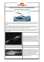
Assembly instructions for the Depron Avro Lancaster - Docu-and-Info
Assembly instructions for the Depron Avro Lancaster - Docu-and-Info
Assembly instructions for the Depron Avro Lancaster - Docu-and-Info
- No tags were found...

Create successful ePaper yourself
Turn your PDF publications into a flip-book with our unique Google optimized e-Paper software.
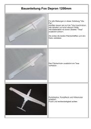
<strong>Assembly</strong> <strong>instructions</strong> <strong>for</strong> <strong>the</strong> <strong>Depron</strong> <strong>Avro</strong> <strong>Lancaster</strong>Please read <strong>the</strong>se <strong>instructions</strong> completely be<strong>for</strong>e commencing with your build.<strong>Depron</strong> is easy to work, but care should be taken when making <strong>the</strong> bends required to complete this model, <strong>the</strong>material is quite brittle, application of heat helps with <strong>the</strong> bending process, a hair dryer can be utilised.Please Note:Do not use products containing solvent on <strong>Depron</strong> material <strong>the</strong> <strong>Depron</strong> will disintegrate,do not use superglue.Test your products on one of <strong>the</strong> 300 x 300mm scrap pieces supplied. Broad felt tip pens or water based Acrylicpaints are suitable <strong>for</strong> colouring.A wide range of <strong>Lancaster</strong> markings <strong>and</strong> camouflage can be found in <strong>the</strong> following website.http://wp.scn.ru/en/ww2/b/555/9/0If you want realistic camouflage colours http://www.warbirdcolors.com/ can supply <strong>the</strong> correct BritishSt<strong>and</strong>ard paints. Paint can be applied by brush or airbrush.If you wish to mark any guide lines on <strong>Depron</strong> you should use a ball point pen with a light touch, or a fine pointfelt tip pen. <strong>Depron</strong> marks easily so any markings should be on <strong>the</strong> inside of <strong>the</strong> parts.Items being joined can be bonded with UHU Por adhesive, 5 min epoxy, or hot glue.Sewing pins or sellotape can be used to hold <strong>the</strong> pieces while <strong>the</strong>y set, please note that sellotape whenremoved may leave a mark where it has removed <strong>the</strong> “bloom” of <strong>the</strong> depron, this will be noticeable whenmaking <strong>the</strong> first paint covering.A kit of parts is also supplied of plywood, wires <strong>for</strong> <strong>the</strong> servos, magnets <strong>for</strong> <strong>the</strong> mounting of <strong>the</strong> bomb baypanel, <strong>and</strong> some spare depron in case of breakages.Some trimming <strong>and</strong> shaping will be required.GB_<strong>Assembly</strong>_<strong>instructions</strong>_lancasterPage 1 of 6
<strong>Depron</strong> Parts KitPet-g partsThe engine nacelles can be partiallyassembled as shown in <strong>the</strong> first picture,<strong>and</strong> <strong>the</strong>n when <strong>the</strong> glue is set, <strong>the</strong>bends required can be made <strong>and</strong> <strong>the</strong>resultant curves glued <strong>and</strong> held inposition with sellotape until set.When assembled, <strong>the</strong> nacelles shouldbe rounded at <strong>the</strong> corners, <strong>and</strong> ventholes cut at an angle to allow <strong>for</strong> motorcooling.Positioning of <strong>the</strong> support arches <strong>for</strong> <strong>the</strong> fuselage coversGB_<strong>Assembly</strong>_<strong>instructions</strong>_lancasterPage 2 of 6
A series of arches have been supplied,<strong>the</strong>se can be glued in place on <strong>the</strong> front<strong>and</strong> rear main frames <strong>the</strong>y will give aguide <strong>for</strong> <strong>the</strong> fixing of <strong>the</strong> fuselage sidesections.Positioning of <strong>the</strong> aerofoil profiles <strong>and</strong> main <strong>and</strong> wing spars, <strong>and</strong> <strong>the</strong> dihedral.The wing <strong>and</strong> main spars should be spliced where <strong>the</strong>y join.The wings should be assembled in two pieces separated at <strong>the</strong> centre, in order that <strong>the</strong> wings can beinserted into <strong>the</strong> fuselage. Cuts will have to be made in <strong>the</strong> aileron profiles, <strong>and</strong> <strong>the</strong> slot in <strong>the</strong>fuselage to accommodate <strong>the</strong> spars <strong>and</strong> also allow <strong>the</strong> laying of <strong>the</strong> wiring to <strong>the</strong> motors <strong>and</strong> servos.Fitting <strong>the</strong> wings will depend uponwhe<strong>the</strong>r or not you want to be able tomake <strong>the</strong> wings removable. In thisexample a connection has been madefrom styrene tube <strong>and</strong> round dowel.(Not included in <strong>the</strong> kit). These partsare easily available at hobby shops <strong>and</strong>some hardware stores. If you intend tomake <strong>the</strong> wings fixed, each wingsection should be fully completed with<strong>the</strong> wiring laid in <strong>for</strong> <strong>the</strong> motors <strong>and</strong><strong>the</strong> servos, <strong>and</strong> <strong>the</strong> upper surfacecovered. The upper profile will be cut into <strong>the</strong> fuselage <strong>and</strong> <strong>the</strong> wings set into<strong>the</strong> fuselage.GB_<strong>Assembly</strong>_<strong>instructions</strong>_lancasterPage 3 of 6
Be<strong>for</strong>e you cover <strong>the</strong> upper wingsurfaces, ensure that you have laid in<strong>the</strong> wiring <strong>for</strong> <strong>the</strong> motors <strong>and</strong> aileronservos. This will require cuttingpathways through <strong>the</strong> aerofoils <strong>and</strong>small holes in <strong>the</strong> lower wing.You should first chamfer <strong>the</strong> leading<strong>and</strong> trailing edges of <strong>the</strong> wing sections,<strong>and</strong> <strong>the</strong>n glue <strong>the</strong> upper covering along<strong>the</strong> leading edge, leave this to setbe<strong>for</strong>e bending <strong>the</strong> covering <strong>and</strong> gluingit at <strong>the</strong> trailing edge.Laying in <strong>the</strong> wiring.If <strong>the</strong> wings are to be gluedpermanently in position <strong>the</strong>y shouldnot be assembled into <strong>the</strong> fuselageuntil <strong>the</strong> upper wing covers are inplace.When <strong>the</strong> wings are covered <strong>and</strong> set, <strong>the</strong> ailerons can <strong>the</strong>n be cut at <strong>the</strong> trailing edges.After shaping, <strong>the</strong> tail plane can now beinserted <strong>and</strong> glued into place, <strong>the</strong>n <strong>the</strong>balsa leading edge <strong>for</strong> <strong>the</strong> elevatorsshould be placed alongside <strong>the</strong> tailplane.After tapering <strong>the</strong> elevators, <strong>the</strong>y can<strong>the</strong>n be glued in position as shown.The elevator servo, <strong>and</strong> servo armsshould now be installed, <strong>the</strong> wingsinserted <strong>and</strong> <strong>the</strong> rest of <strong>the</strong> RCequipment installed, <strong>and</strong> tested, thisshould all be done prior to fitting <strong>the</strong>upper <strong>and</strong> lower fuselage covers.GB_<strong>Assembly</strong>_<strong>instructions</strong>_lancasterPage 4 of 6
This is because when ready <strong>the</strong> profilewill be traced on <strong>the</strong> side panels <strong>and</strong><strong>the</strong> wings set into <strong>the</strong> side panels byabout 6mm (The width of <strong>the</strong> depron)This model was made with removablewings.Ready now to prepare <strong>the</strong> upper <strong>and</strong>lower fuselage coverings.To shape <strong>the</strong> upper <strong>and</strong> lower fuselagecovers a 45mm dia rolling pin was used,any similar rod or tube can be utilised.The <strong>Depron</strong> was bent <strong>and</strong> held inposition with sellotape. It was warmedup using a hair dryer <strong>and</strong> <strong>the</strong>n it was<strong>the</strong>n left overnight. <strong>Depron</strong> when left in<strong>the</strong> same position <strong>for</strong> a reasonable timewill “set” <strong>and</strong> retain <strong>the</strong> shape.GB_<strong>Assembly</strong>_<strong>instructions</strong>_lancasterPage 5 of 6
The centre of gravity is 50mm from <strong>the</strong> leading edge of <strong>the</strong> wing, on <strong>the</strong> main spar.50mmC of GDo not <strong>for</strong>get that, unless you build inaccess panels, all of <strong>the</strong> RC equipmentmust be inserted be<strong>for</strong>e you cover <strong>the</strong>wings <strong>and</strong> fuselage. An access panel <strong>for</strong>battery change should be made where<strong>the</strong> bomb bay would be situated.We hope that you have a lot of fun flying your own <strong>Lancaster</strong>GB_<strong>Assembly</strong>_<strong>instructions</strong>_lancasterPage 6 of 6