TECHNICAL MANUAL - Pro-Cut USA On-Car Brake Lathes
TECHNICAL MANUAL - Pro-Cut USA On-Car Brake Lathes
TECHNICAL MANUAL - Pro-Cut USA On-Car Brake Lathes
- No tags were found...

Create successful ePaper yourself
Turn your PDF publications into a flip-book with our unique Google optimized e-Paper software.
P F M 9 0 0 S M A R T L AT H E<strong>TECHNICAL</strong> <strong>MANUAL</strong>Step 4:Make the <strong>Cut</strong>P R O - C U T I N T E R N A T I O N A L8 0 0 . 5 4 3 . 6 6 1 8
TE CHNICAL MANUA L
Our Mission<strong>Pro</strong>-<strong>Cut</strong> International is dedicated to providing ourc u s t o m e rs with the most adva n c e d ,p re c i s e, a n dp ro f i t a ble tools for brake re p a i r. We havewo r ked with, l e a rned fro m , and solved pro b-lems for people at all levels of the brake re p a i rbusiness — from the largest auto manu fa c t u re rsand national service chains to one-bay, o n e -man operations. It is a business our entire staff live s , e a t s , and bre a t h e s .We we l c o m eyou to our table and look forwa rd to working with you to improve your brakes e rvice bu s i n e s s .S a fety and Warning Info r m a t i o nThe PFM 900 SmartLathe is a precision instrument which re q u i res close attention while ino p e r a t i o n .It will provide many ye a rs of service if it is operated safely. Safety is eve ryon e ’s re s p o n s i b i l i t y.T h e re f o re,b e f o re a s s e m bling or operating this lathe,you must dothe follow i n g :1 ) Read and understand the owner’s manual in its entirety.2 ) Always wear protective eyewear when operating the lathe. Small particles producedduring rotor cutting can cause severe damage to the eyes.3 ) Never wear loose-fitting clothing while operating the lathe. The lathe containsmoving parts which could catch or grab clothing that is not secure.4 ) Keep hands away from moving parts during operation.5 ) Keep body parts free of electrical connections. This lathe runs by electricity. As withall electrical equipment, care must be taken to avoid shocks and other electricalinjury.
C o n t e n t sivIntroduction1 A d d ressing and Solving Customer <strong>Brake</strong> Concerns2 PFM900 Lathe Overview3 Setting Up a New Lathe4 Vehicle Preparation5 Where to Start - Driver or Passenger Side?6 Lathe Preparation7 Machining Rotors: The 4/10 SolutionStep 1:Step 2:Step 3:Step 4:Mount the AdapterSet Up the LatheAdjust for Lateral RunoutMake the <strong>Cut</strong>13 Machining the Opposite Side14 Vehicle Reassembly14 Maintenance15 Troubleshooting: Assuring a Smooth Finish18 Troubleshooting: Lateral Runout Adjustment19 Reading the Binary Codes20 Adapter Guide21 PFM900 Parts Diagram
ivI n t ro d u c t i o nThe PFM 900, the world’s first fully automatic,on-car brake lathe.C o n gratulations on your purchase of the P RO - C U TPF M900, the world’s first fully automatic, computerized oncarbrake lathe.For many years, on-car lathes were used only for rotors thatwere difficult to remove. Due to current trends,virtually all automanufacturers now require or recommend the use of on-cartechnology. By matching a rotor to the hub, the PFM900achieves superior accuracy with breathtaking speed. There issimply no better way to resurface a rotor than with the patentedPFM900.The following pages are designed to guide you through setup,o p e r a t i o n , and maintenance of your lathe.We also re c o m m e n dthat you view the enclosed PFM900 training video.Also enclosed in the Resource Kit binder is your PFM900warranty activation card. Please take a moment to fill out theform and send or fax it back to us so we can register you for your12-month warranty.If you have any questions along the way, please call us.Our technicalsupport team is standing by from 8 a.m. to 5 p.m. Easterntime. Or browse our website for technical information and tips:www.procutinternational.com.We l c o m e t o t h e P r o - C u t Te am !
Customer B rake Concerns1A d d ressing and SolvingCustomer <strong>Brake</strong> ConcernsRunout in the rotor leads to thickness variation.Th i c k n ess variation is felt as brake pedal pulsation.It is this pulsation that res u l ts in a customer complaint.<strong>Pro</strong>-<strong>Cut</strong> matches the rotor to the hub, therebyeliminating runout, the root cause of pulsa t i o n .LAT ERA L RUNOUT leads to ...T HICKNESS VA RI AT ION which results in ...BRA KE PEDAL PULSAT IONB r a ke pedal pulsation is most often the result of thickness va riation in the brakero t o r. Thickness va riation is the technical term for a rotor that is notu n i f o rmly thick. N ew ro t o rs are uniformly thick, and stop the ve h i c l es m o o t h l y. But thickness va riation can develop over time and eventually leadto brake pedal pulsation.H ow does thickness va riation deve l o p ? T h rough lateral runout in the face of thero t o r.Lateral runout is the technical term for “ wo b bl e,”and is a measure m e n tof how much the surface of the disc wo b bles from side to side as it ro t a t e s .A rotor with lateral runout will not wear eve n l y,and distortion increases ove rt i m e. As the vehicle moves down the road with the brakes re l a xe d ,the ro t o rwill brush each pad once per revo l u t i o n ,resulting in a thin spot on the ro t o r.Since vehicle hubs often have lateral runout due to stacked component tolerances, a new orn ewly machined rotor will often exhibit excessive lateral runout as it turns on theh u b. Most manu fa c t u re rs re q u i re rotor runout to be below 0.003".The PFM900 allows you to match eve ry rotor to the hub on which it turn s . The on-boardcomputer delive rs a precise alignment between the lathe axis and the hub axis,t h e re byguaranteeing that a <strong>Pro</strong>-<strong>Cut</strong> machined rotor will have less than 0.002" lateral ru n o u teve ry time.By machining the rotor tomatch the hub assemblyon which it sits, latera lrunout can be eliminated.PRO - CU T : 800-543-6618
2 Lat he Ove r v i e wPFM 900 Lathe Ove r v i e w35 61221311181447109COMPONENTS1. PFM900 Computer Box2. <strong>On</strong>/Off Switch3. .75 hp Motor4. Mounting Knob5. Adjuster Flange6. Adjuster Solenoid7. Feed Kn o b /Feed Engage Plunger8. Trolley Handle9. Automatic Shut-off Switch10. Automatic Shut-off Cam11. <strong>Cut</strong> Depth Adjustment Dials12. <strong>Cut</strong>ting Tips/Inserts13. <strong>Cut</strong> Head Lock Knob14. Tr o l l e yPRO - CU T : 800-543-6618
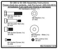
Setting Up a New Lathe3Setting Up a New La t h eBefore you begin setting up, check contents against theparts diagram enclosed in the lathe package. If you aremissing any parts, call <strong>Pro</strong>-<strong>Cut</strong> immediately.ASSEMBLE THE TROLLEYOpen the tro l l ey box and check contents against the parts diagr a m . If you are missing anyp a rt s , call <strong>Pro</strong>-<strong>Cut</strong> immediately. P roceed with assembl y, f o l l owing the instru c t i o n senclosed in the box .MOUNT THE LATHE TO THE TROLLEY<strong>On</strong>ce the tro l l ey is assembled you will need to mount the lathe to thet ro l l ey. The easiest way to do this is to re m ove the mount armf rom the tro l l ey and assemble it onto the body of the lathe.1 ) R e m ove the tro l l ey handle ( 3 7 - 4 5 6 ) and thrust washer ( 3 7 - 2 5 1 )and slidethe support arm ( 5 0 - 5 3 3 ) out from the L-Tube ( 5 0 - 5 0 9 ).2 ) Slide the thick spacer ( 5 0 - 5 3 7 ) over the ve rtical post on the supporta rm ( 5 0 - 5 3 3 ), and place one of the rubber wa s h e rs ( 3 7 - 5 1 9 ) over thes p a c e r.3 ) R e m ove the lathe body from the shipping pallet and turn it upside dow n . Slide thes u p p o rt arm (complete with spacer and rubber washer) ve rtical post through the holein the main lathe body. Position the support arm so that the slot on the flat port i o nrests over the mounting lug on the bottom of the lathe body. Place the other ru b b e rwasher ( 3 7 - 5 1 9 ) b e t ween the mounting lug and the flat portion of the support arm ,and then thread the male tro l l ey knob ( 3 7 - 5 1 8 ) t h rough the support arm and into themounting lug.4 ) Tu rn the lathe back over and secure the top of the support arm ve rtical post with thefemale tro l l ey knob ( 3 7 - 5 1 7 ).Connect the trolley arm to the lathe first,then mount the arm/lathe combination tothe tro l l e y.5 ) Position the serrated lock washer ( 3 7 - 6 2 0 ) over the horizontal stud on the support arm .Using proper back protection and lifting pro c e d u re, lift the support arm and latheand fit them into the L-tube assembly ( 5 0 - 5 0 9 ). Slide the thrust washer ( 3 7 - 2 5 1 ) ove rthe threaded portion of the support arm and reattach the tro l l ey handle ( 3 7 - 4 5 6 ).PRO - CU T : 800-543-6618
4 Vehicl e Pr e p a r a t i o nVehicle Pre p a ra t i o nNOTE: Remember to mark rotors before removing them so you canbe sure they are returned to the same positions on the hub.B e f o re lifting the ve h i c l e, the front wheels should be straight and the parking brake shouldbe off, with the transmission in neutral.1 ) Raise the vehicle according to the lift manu fa c t u re r ’s instru c t i o n s .Raise until the wheelhub is about belt leve l .2 ) If any other wheel service is re q u i re d , it should be performed before machining thero t o rs .Check wheel bearings for damage or excessive play.3 ) R e m ove the wheels. R e m ove the brake calipers and suspend them out of the way ofm oving parts such as half shafts and CV joints.4 ) If the rotor is free on the hub, mark and re m ove it in order to assess the mating surfa c e.Use a Scotch-Bri t e T M type wheel on a die grinder to re m ove rust or debri s .Clean allm a t e rial from the mounting are a .5 ) The rotor on the side of the vehicle that is not to be machined should be markedand re m oved if it is free on the hub. Match marking the ro t o rs to the hub is ve ryi m p o rt a n t .6 ) Use a micrometer to measure rotor thickness and determine how much material may bere m oved from the ro t o r.Visually inspect for deep rust or gro ove s .This inspection willhelp determine the depth of the cut.PRO - CU T : 800-543-6618
Where t o Start — Driver or Passenger Sid e?5Wh e re to Start —D r i ver or Passenger Side?The <strong>Pro</strong>-<strong>Cut</strong> PFM900 machines both front and rearrotors. The lathe’s operations do not change at all inthe rear of the vehicle.It is important to start on the proper side. The <strong>Pro</strong>-<strong>Cut</strong> mountsd i rectly to the hub of the ve h i c l e. With the lathe ri g h t - s i d eup the cutting head is to the right of the hub as you fa c ethe vehicle wheel we l l .When machining a rotor the cuttinghead is most often positioned where the caliper ri d e s . <strong>On</strong> avehicle where the calipers ride in front of the hub, a lways starton the passenger side. If the caliper rides to the rear of the hub,b e gin on the drive r ’s side.When you flip the lathe to machine the opposite side of the ve h i c l e,n odifficult adjustments are re q u i red since they we re made in theright-side up position.c u t t inge d g eTIPME A SURE TWICE ,C U T O N C EVehicle preparation is critical.If you pay close attentionto details before mounting thelathe you can be sure the brakejob will go smoothly and quickly.Be especially sensitive to excessivebearing play (which shouldbe addressed before mountingthe lathe) or unusual rotor wear(which may require a deep initialcut to avoid multiple passes ) .Lathe in right-side-up position. Note that adjustmentsto cutting head are simpler in this position.Lathe in upside-down position. You will need to flip thelathe over into this position to machine one side of theve h i c l e .PRO - CU T : 800-543-6618
6 Lat he Pr e p a r a t i o nLathe Pre p a ra t i o nNOTE: Use only <strong>Pro</strong>-<strong>Cut</strong> <strong>Cut</strong>ting Tips (50-701 or 50-741). Althoughother tips will fit the machine, only <strong>Pro</strong>-<strong>Cut</strong> tips have been specificallyengineered in tandem with the <strong>Pro</strong>-<strong>Cut</strong> lathe. Using a non-<strong>Pro</strong>-<strong>Cut</strong> tipmay compromise lathe performance and result in poor surface finish.CHECK CU TT ING TIPSNOTE: The lathe has a powerful 3 ⁄4 hp motor which requires20 amp service. All extension cordsmust be at least 12 gauge and les sthan 25 feet; drop light cords arenot recommended.B e f o re mounting the lathe check the cutting tips and make sure they are ready for use.Thecutting tips are one of the most critical components of the machine.It is vital that theya re <strong>Pro</strong>-<strong>Cut</strong> brand tips in good condition and properly mounted. Each cutting tip hast h ree corn e rs which may be used. The correctly installed tip is wider onthe top and has a gro ove,or letters ,facing up. A tip mounted upside dow nwill produce a surface finish that looks like a re c o rd .You should get at least 7 cuts per corn e r. H oweve r, tip life is affected byva ri a bles such as rust or ri d g e s . In order to determine when to ro t a t et i p s , monitor rotor finish. If the rotor finish begins to look inconsistentor feels rough to the touch, tips should be ro t a t e d .Tips that are chippedor cracked should never be used.Be sure that the tip pocket is clean before positioning the tip. A ny foreign material pinchedunder the tip will cause pro bl e m s .This is the standard <strong>Pro</strong>-<strong>Cut</strong> tip (50 - 70 1 ) .The letters V, B, and G are stamped in eachof the three corners. When the tip ismounted corre c t l y, the letters face up.This is the premium <strong>Pro</strong>-<strong>Cut</strong> tip (50 - 74 1 ) .When the tip is mounted corre c t l y, thechip breaker faces up.PRO - CU T : 800-543-6618
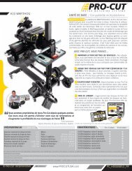
Machining Rot ors7Machining Rotors:The 4/10 SolutionUsing the PFM900 is simple. In just 4 steps over 10 minutes any tech canperform top-quality brake work. We call it the 4/10 Solution.Step 1: MOUNT THE ADAPTER (2 minutes)Step 2: SET UP THE LATHE (2 minutes)Step 3: ADJUST FOR LATERAL RUNOUT (1 minute)Step 4: MAKE THE CUT (5 minutes)The 4/10 Solution — 4 steps over just 10 minutes to perform topqualitybrake work. If these steps are followed properly oneach brake job, the <strong>Pro</strong>-<strong>Cut</strong> PFM900 will operate accuratelyand efficiently.Step 1: MOUNT THE ADAPTER (2 minutes)The first step is to choose the proper adapter. Most passenger carsrequire either the four (50-687) or five lug (50-688) Direct Fit ®adapter.Some larger passenger cards and smaller trucks use the50-695 adapter. For most trucks and vans,use the larger adapter(50-691).This fits 5, 6, 7, and 8-lug vehicles. (See the completeadapter guide on page 20).<strong>On</strong>ce yo u ’ve selected the correct adapter,t ry each bolt pattern until yo ufind the one that fits the vehicle eve n l y. When possibl e, use thenuts provided with the machine. Hand tighten nu t s .Do not useimpact wrenches to mount adapters .Nuts should be hand-tightenedto 25–30 ft. l b s .Excess torque will damage the adapter.Some 4-wheel-drive vehicles require that you remove the cap fromthe locking hub. Some also require the use of a spacer (30-791or 50-246). If the adapter doesn’t fit flush and square, use thespacer. Sometimes the holes in the spacer are not needed asthe entire bolt pattern will fit in the center of the spacer.Step 1 of the 4/10 Solution:Technician mounts an adapter to the hub.WA RNING : The adapters aremade of cast iron, not aluminum orsteel like wheels. They are notd esigned to withstand the use ofimpact tools. DO NOT USE IM -PA CT GUNS TO ATTA CH THESEA DA PT ERS. Twenty to thirty ft.-lbs. applied by hand is plenty tosecure the adapter to the vehicle.DO NOT USE IMPA CT WREN -CHES TO TIGH T EN LUG NU TS .E x c ess torque applied with animpact wrench will damage theadapters. Warranty does not coverthis misuse.PRO - CU T : 800-543-6618
8 Machining RotorsThe 4/10 Solution, cont.Step 2: SET UP THE LATHE (2 minutes)Step 2 of the 4/10 Solution: technicianmounts the lathe to the adapter.c u t t inge d g eTIPSE CU RING THECUTTING HE A DVibration is the root ca u s eof most surface finish problems.Be sure the cutting headis securely locked in place withthe back tight against the dovetail.Tight connections here reducethe chance of vibration.a. Mount the lathe to the adapterMove the cutting head out so that the tips will not strike the rotor asyou mount the lathe.Next, roll the machine into place and match it up with the adapter.Note that the trolley moves up and down to accommodate differentheights. The small dowel pin on the face of the adapter will fit intoeither of the two holes on the runout adjustment flange. Turn themounting knob to thread the center axle of the lathe with the adapter,securely connecting the lathe to the vehicle.NOTE: It is ve ry important that the machine be mounted smoothlyonto the adapter without prying or forc i n g .Ta ke the time to alignthe machine properly in order to avoid damage to the ru n o u tadjustment flange. The large mounting knob will tighten ve ryeasily when the machine is properly aligned.Tighten it snu g l y.b. Position the lathe for cuttingLoosen the trolley handle so that the machine is free to rotate. Rotatethe machine so that the cutting head is in a position where there isclearance to make the cut. Be sure to check the back side of the rotorfor obstacles. Make sure there will be clearance for the chip silenceras well.c. Position cutting head and set shut-off camNotice that there are several mounting holes in the slide plate that canbe used to lock the cutting head. The cutting head assembly can besecured into any one of the holes. It is a good idea to clean out theseholes as well as the dovetail and plate surfaces when you changecutting head position, as they can easily fill up with metal chips. UsePRO - CU T : 800-543-6618
Machining Rot ors9the T-handle 6mm allen wrench to remove the securing screw andcenter the head so the cutting arms will straddle the rotor.It is critical that you pull the tool holder plate back into the dovetailso that it is square as you tighten the securing screw.You can use onehand to push the cutting head firmly back into the dovetail as youtighten the set screw with your other hand. If the tool holder is notsquarely and firmly pressed into the dovetail, a poor surface finishwill result.NOTE: The <strong>Pro</strong>-<strong>Cut</strong> will mount right-side up on one side andupside down on the other. Always start right-side up; this way,when you proceed to the other side of the vehicle, the offset ofthe cutting head will already be set, with the cutting head firmlyin the dovetail. Never attempt to move the cutting head laterallywith the lathe upside down.Next you will set the shut-off cam. Crank the feed knob until the tipsclear the outside edge of the rotor. Loosen the cam screw and slide thecam back until it contacts the automatic shut-off switch plunger.Tighten the cam screw. The cam will press the shut-off switch whenthe tips clear the rotor. This allows for unattended operation.The cutting head connects to the cuttingplate (50-499) by a bolt. The bolt threadsthrough one of tapped holes in the plate.Different holes in the plate allow the cuttinghead to be set for any vehicle.WARNING: If the tool holder isnot squarely and firmly pressedinto the dovetail, a poor surfacefinish will result.WA RNING : Never attempt tomove the cutting head laterallywith the lathe upside down.Note the dovetail at the back of the cuttinghead. This dovetail must be tight. Be sure topull back on the cutting head as you securethe mounting bolt.PRO - CU T : 800-543-6618
10 Machining RotorsThe 4/10 Solution, cont.Detail of the PFM900 computer box.Step 3: ADJUST FOR LATERAL RUNOUT (1 minute)You must adjust for lateral runout to eliminate wobble (runout) from the machinebefore cutting.This procedure ensures the resulting machined rotor will have minimalrunout after cutting.The PFM900 has been calibrated to reduce runout to lessthan 0.002" as measured on the rotor.a. Compensate for runoutThe PFM900 compensates for runout automatically.With the machinemounted and running, press the start button and hold for 2 seconds.This will initiate the measurement/adjustment process.The “adjusting”light will illuminate,and the adjuster solenoid will change the angle (atthe adjustment flange) until the lathe rotates with minimal runout.Thisprocedure will usually take between 10 to 60 seconds.Total adjustmenttime depends on a number of factors including initial runout and theresistance in the hub. Average adjustment time is less than a minute.When the machine is done adjusting, one or more lights will give feedback on the statusof the lathe.When either green light is lit, the machine is ready to cut.If both green lights areon,the machine has reduced the runout to less than 0.001".If only one green lightis on, the machine had more difficulty adjusting for runout due to any number offactors, but eventually reached a level of runout that is acceptable (less than 0.003"runout).You may try again as the machine may be able to reach the optimum levelof runout with additional attempts.If the t ry again light is illuminated, the machine has failed to fully adjust forrunout.This difficulty could be due to looseness of fittings, irregular runout, damageto wheel bearings or other components,or other factors.The best procedure isto loosen the machine from the adapter, rotate the wheel 180 degrees, and attachthe machine again.Make sure that the machine is adequately supported by the trolley.Run the adjustment procedure and the machine will again adjust for runout.IfPRO - CU T : 800-543-6618
Machining Rot ors11t ry again appears repeatedly, there is most often a problem with the vehicle. Youshould dismount the machine and check for a damaged wheel bearing or cv joint.Such problems will have to be addressed before machining is possible.If the machine seems to be having excessive difficulty inadjusting for lateral runout, consult the Troubleshootingsection on page 18.Step 4: MAKE THE CUT (5 minutes)1 ) Loosen the clamp knob on top of the cutting head.2 ) Turn cut-depth knobs counter-clockwise until the tips can clearboth sides of the rotor. Turn on the lathe. Crank the cuttinghead forward to the middle of the braking surface of the rotor.3 ) Start with the inside (behind the rotor) tool arm.Turn the depthknob clockwise (tighten) until the tool tip just barely makescontact with the rotor surface.You can listen for the contact.Next move the outside tool arm in until it also makes contact.4 ) Now, advance the cutting head in towards the center of the rotor.Be careful not to crank the cutting arms into the “hat”of therotor.5) When you are at the inside edge of the pad contact surface, youmay adjust for depth.Each line on the knob moves the cuttingtip 0.002". <strong>Cut</strong> at least 0.004" on each side with each pass.The maximum depth is 0.015" on each side.6 ) Now that you have adjusted for depth, tighten the clamp knob(over the cutting arms).This must be tight to minimize vibration.Place the chip deflector/silencer over the cutting tips.This silencer is very important,and it should be used on everyrotor to prevent vibration.Technician sets cut depth.WARNING: It is extremely impo rtant not to touch the hat of therotor with the left tool holder. Th i swill damage or break the toolholder plate. This type of damageis not covered by the warranty.PRO - CU T : 800-543-6618
12 Machining RotorsThe 4/10 Solution, cont.c u t t inge d g e If the rotor is severelyworn it may be necessaryto machine away theTIPr i d g es on the inside ando u tside of the pad conta c tarea before machining thepad contact surf a c e .7 ) Press the feed engage crank handle to engage the automatic feed.The machine will shut off when the cut is finished.The cut will taketwo to four minutes depending on the size of the rotor.8 ) When you are finished cutting, manually crank the cutting headout beyond the rotor for lathe removal. Loosen the mounting knoband remove the lathe from the adapter. Be careful not to bump eitherthe rotor or the wheel well as you dismount the lathe.Take special carenot to bump the tips into the rotor.9 ) Before removing the adapter, measure and record the lateralrunout on the rotor. Also measure and record the thickness to ensurethat it is above “machine to” specification. When you have finishedyour measurements, be sure to clear the hub area of any brake chips,dust, or debris.10 ) If the rotor is loose on the hub, secure the rotor with a lug nutbefore machining the other side. If you remove the rotor after machining,you must mark it so it can be remounted in the correct (same)position.Turn the dials to advance the cutting head.Each line on the dial indicates 0.002”.The chip deflector rides over the cutting armsas shown above. The chip deflector shouldbe used every time.Move the cutting head by turning the knobshown above.PRO - CU T : 800-543-6618
Mach ining t he Opposite Side13Machining the Opposite SideBe sure the auto cut-off switch is not stillengaged from your first cut.1 ) Loosen the trolley handle and rotate the machine into the upsidedownposition.WARNING: Advancing the cuttinghead towards the hat of therotor requires even more ca r ewhen upside down. Be careful notto bump the hat of the rotor!2 ) The procedure for cutting in the upside-down position is thesame, though fewer steps are needed since all settings havealready been made. The lathe mounts in the same manner.Often,the shut-off switch will still be depressed from the previouscut,so the machine will not turn on until you move thecutting head.The cutting arms will also still be advanced in from the last cut,so besure to loosen the clamp knob and spread the arms before feeding the head towardsthe center of the rotor. Measuring and adjusting for runout is exactly the same asin the upright position.The entire cutting process is also the same, right down tothe silencer clip which mounts upside down in the exact same position.After loosening the trolley handle, the lathe can be flipped over to machine the opposite side of the vehicle.PRO - CU T : 800-543-6618
14 Vehicl e Reassembly / MaintenanceVehicle ReassemblyBe sure to use a TorkStik when remounting the wheel. Excess or uneventorquing of lug nuts will ruin any brake job.When machining on both sides is complete, clean any dust or debris from the finished rotorwith 150 g rit sandpaper and then a damp rag. Cast iron dust left on the rotor cancause brake squeal. All surfaces should be cleaned of chips and dust. Special careshould be used in making sure that abs sensors are free of debris. Reassemble thebrakes and wheels to the manufacturer’s specifications.M a i n t e n a n c eThe <strong>Pro</strong>-<strong>Cut</strong> lathe is simple and rugged. With just a few maintenance tips you canensure a long and profitable life for your machine.DAILY MAINTENANCECheck tool tip edges. If there are chips or dings, turn or replace the tip. Be sure they areright-side up so that the groove or V, B, G letters are visible. Each tip has threecutting points.When worn out, replace them.When changing tool tips, clean thethreads and put a spot of Vaseline ® (or thick grease) in the bottom of the screw holebefore tightening the tool bit screw. The Vaseline will stop chips from accumulatingin the hole and rusting in place. If chips do rust in place they can often bedislodged by poking a needle through the hole.Clean the tool holder plate (50-499), taking special care that there are not chips or dirtwedged in the dovetail.Check the electrical connections and cord for cuts in insulation or wear.PRO - CU T : 800-543-6618
Maintenance / Tr o u b l e s h o o t i n g15WEEKLY MAINTENANCELubricate the cut depth adjustment wedge threads with a thin coat of light machine oil.Check the tool holder plate for damage.Slide a 0.003" feeler gauge between the tool holderplate and the base plate (50-499). If it can be inserted freely your tool holder plateis damaged. A damaged tool holder plate will often cause a vibration during thecut.This will leave a herringbone pattern on the rotor.Check the tool holder for lateral play. Lateral play often causes ridges and matching grooveswhen a rotor is resurfaced. To check for lateral play, grab the tool arm assembly andtry and rotate it diagonally. There should be no motion.If there is motion, you willneed to tighten the gib (see the section below).Tro u b l e s h o o t i n g :Assuring a Smooth FinishThe <strong>Pro</strong>-<strong>Cut</strong> PFM 900 should provide a smooth surf a c efinish on every cut, free of chatter, tone, or roughness. Ifyour machine leaves a substandard, “chattery” or roughfinish, you need to find the problem. Below are the commonsources of poor surface finish and ways to remedythe problem.<strong>Brake</strong> performance is dependent upon rotor surface finish.The <strong>Pro</strong>-<strong>Cut</strong> lathe has beendesigned to give you a superior surface finish on any rotor as long as proper maintenanceis followed.Minimized vibration during machining is the key to high-quality surface finish. It iscritical that all contact points between the rotor and the lathe are secure.Specifically, the connections between lathe and adapter; the slide plate and thelathe; the cutting head and the plate; and the tips and the tool holders. Loosenessin any of these areas will compromise lathe performance and surface finish.PRO - CU T : 800-543-6618
16 Tr o u b l e s h o o t i n gCHECK CUTTING TIPSThe cutting tips must be right-side up. Letters face up. The cutting tips should not havechips or dings in the surface of the points. Do not take cuts of less than 4 thousandthsof an inch unless absolutely necessary. <strong>Cut</strong>s of 4 to 10 thousandths willprovide the best surface finish and the longest tip life.MAKE SURE CUTTING HEAD IS SNUG<strong>On</strong> each brake job, the technician must center the cutting head for that particular ve h i c l e, u s i n gone of the holes on the slide plate.<strong>On</strong>ce the head is centere d ,it is vital that the technicianuse one hand to push the head firmly and squarely back into the dovetail onthe slide plate while using the other hand to tighten the allen bolt that secures theh e a d .F a i l u re to do this will result in chatter.USE THE CHIP DEFL ECTORThe chip deflector reduces vibrationand must be used on everycut.The chip deflector included with the lathe is a critical component.The pre s s u re ofits pads provides a great deal of dampening that reduces the chance of vibrationwhile cutting. The chip deflector must be used on eve ry cut to ensure properf i n i s h .N ew chip deflectors can be purchased directly from <strong>Pro</strong> - C u t .Detailed Schematic of the <strong>Pro</strong>-<strong>Cut</strong> <strong>Cut</strong>ting Headslide plateallen boltgibfeed screwallen setlock nutconnecting platePRO - CU T : 800-543-6618
Tr o u b l e s h o o t i n g17CHECK FOR BENT TOOL HOL DER PLAT EThe tool holder plate holds the cutting arms. It will bend or break ifthe technician accidentally runs the cutting arms into the hatof the rotor while the lathe is turning.To diagnose whether or not the plate is bent,place it on the slide plateand try to slide a 0.003" feeler gauge between the two plates.If the feeler gauge can be inserted freely, the tool holder plateis bent and needs to be replaced.T IGH T EN THE GIBPoor finish quality can be the result of a loose cutting head. As wear occursb e t ween the slide plate and the box it rides on, you must take upthe slack. You do this by tightening the move a ble wedge we callthe “ gi b.” ( 5 0 - 4 6 4 )If the cutting head can be moved from side to side at all, it shouldbe tightened. To adjust the gib, first loosen all four set screws(with 2.5mm allen wrench) by freeing the 7mm lock nut andloosening the allen set screw. Remove the plate and gib completely,and clean the contact surfaces. Locate the plate in themiddle of the rail with the gib between the plate the the rail.Be sure the 4 notches of the gib are aligned the catch the allenset screws as they’re tightened through the plate. Tighten eachallen set screw until you feel it snug against the gib. Hold lightpressure with the allen wrench as you lock the screw downwith the 7mm lock nut. After tightening each nut, slide the plate to make surethere is no binding. When the gib is adjusted properly, the plate will havesome resistance as it slides, with no lateral movement possible.To reattach the feed block,move the slide plate as far forward as it can travel,and wind thefeed block in to meet it.This ensures that the feed block will be properly centered.Wind the head back out and the machine is ready for use.Checking the tool holder plate for damage.The toolholder plate is bent if a 0.003” feelergauge can fit between the cutting head andthe mounting plate. This condition leads tocompromised surface finish.Detail of the gib that rides between the gearbox and cutting plate.PRO - CU T : 800-543-6618
18 Tr o u b l e s h o o t i n gTro u b l e s h o o t i n g :La t e ral Runout AdjustmentThe PFM900 can be calibrated to adjust to tighteror looser standards.If the machine is having difficulty adjusting for lateral runout, first assess the vehicle beingserviced. If lateral movement is rough or uneven due to damaged vehicle components,these components must be repaired or replaced before rotors are machined.It is also important that the machine be supported by the trolley during adjustment.If the problem seems to be with the brake lathe itself, you may re-calibrate the machineaccording to the procedure outlined below.If the machine displays a green light when there is still excessive runout in the system, youshould tighten the calibration.If the machine does not display the green light even when runout has been minimized,youshould loosen the calibration.CALIBRATION PROCEDUREThe PFM900 is calibrated with an “acceptance nu m b e r.” To tighten the calibration, yo uneed to l ower the acceptance nu m b e r. To loosen the calibration, you need toraise the acceptance nu m b e r. H e re ’s how to raise or lower the acceptance nu m b e r:1 ) With the brake lathe plugged in but not turning, push reset and wait for the readyto start light to be illuminated.2 ) With the ready to start light illuminated, press and hold the cal i b rat i on button(located just below the lights) until the adj u st i ng light illuminates, then releasethe cal i b rat i on button.3 ) N ow the machine is displaying the acceptance number using a simple binary code.E a c hflashing light re p resents a nu m b e r.The lowest green light is wo rth 1, the next lightup is 2, the next light is 4, the next light is 8 and the top (ready to start) light is1 6 .So if the lowest light only was lit,the acceptance number would be one. If eve rylight was lit, the acceptance number would be 31 (1+2+4+8+16). Add the va l u e sof the lights which are lit. Generally this should total 18-22.PRO - CU T : 800-543-6618
Troub lesho oti ng / R eading t he Binary Co des194 ) To raise the acceptance number (loosen the calibration), press the start button once.To lower the acceptance number (tighten the calibration), press the cal i b rat i onbutton once.The acceptance number will change in increments of two. After raisingor lowering (you’ll see the binary code change), hit the reset button to savethe change.5 ) <strong>On</strong>ce you have raised or lowered the acceptance number by two and hit reset, test themachine to ensure that the problem has been solved. You may need to repeat theprocedure once or twice to fully solve the problem.If you have any difficulty or questions about executing this procedure, call <strong>Pro</strong>-<strong>Cut</strong>.Reading the Binary CodesHigher binary codes will yield a wider acceptancerange. Lower binary codes result in tighter acceptancebands.When the machine displays the binary codes, add the total of all the flashing lights.START BUTTON168421ADJUSTING LIGHTRESET BUTTONCALIBRATION BUTTONThe illustration above shows binary values for each light. For example,when the 2nd and 4thlights are bl i n k i n g ,the total binary value is 10 (2 for light #2, plus 8 for light #4).PRO - CU T : 800-543-6618
20 Ada pter GuideAdapter Guide50-687 4-Hole DIRECT FIT ® AdapterThis adapter fits 4-lug cars except certain Subarus. (See 50-691 below for older Subarus).Basic Package / Master Package50-688 5-Hole DIRECT FIT ® AdapterThis adapter fits small 5-lug vehicles.Most 5-lug cars (except Full size) and a few light truckscan be machined using this adapter. Basic Package / Master Package50-595 GM/Dakota DIRECT FIT ® AdapterThis adapter has 5-lug patterns for large cars and small 5-lug trucks. It also has the6-lug Dodge Dakota pattern. Master Package50-691 4x4 DIRECT FIT ® AdapterThis adapter has 5-, 6 - ,7 - , and 8-lug patterns to fit most trucks up to one ton. (<strong>On</strong> some ve h i-c l e s ,the 3-791 spacer must be used with this adapter.) Dual wheel trucks and larger Fo rd tru c k sre q u i re optional adapters listed below. N OT E :The large Subaru “ 4o n 1 4 0 m m ”p a t t e rn is alsoon this adapter. Master PackageOptional AdaptersG E N U I N EPRO - CU TP A R TYour assurance of highes t -quality manufacturing andguarantee against defectsin workmanship.50-683 Heavy Duty Ford DIRECT FIT ® AdapterThis optional adapter is necessary for machining many 8-lug FordTrucks and Vans.50 - 684 Dual Wheel Pickup DIRECT FI T ® A d a p t e rThis optional adapter is necessary for machining front ro t o rs on dualwheel tru c k s . Dual wheel Fo rds also re q u i re a cutting head extensi o n .( N o t e : the PFM900 also re q u i res 50-046 to machine duallies.)50-696 Rover AdapterThis optional adapter is necessary for machining Land Rovers andRange Rovers with the large “5on165mm” bolt pattern.PRO - CU T : 800-543-6618
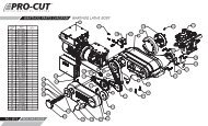
PF M 9 00 Parts Diagram21PFM 900 Parts Diagra m50-238 <strong>Cut</strong>ting HeadPRO - CU T : 800-543-6618
22 PF M 900 Parts Di agramBevel Gear BoxPRO - CU T : 800-543-6618
PF M 9 00 Parts Diagram23PFM900 Lathe BodyPRO - CU T : 800-543-6618
24 PF M 900 Parts Di agram<strong>Pro</strong>-<strong>Cut</strong> TrolleyPRO - CU T : 800-543-6618
P R O - C U T I N T E R N AT I O N A L 1 0 Te c h n o l o g y D r i v e , # 4 , W e s t L e b a n o n , N H 0 3 7 8 48 0 0 . 5 4 3 . 6 6 1 8 6 0 3 . 2 9 8 . 8 4 0 4 i n f o @ p r o c u t i n t e r n a t i o n a l . c o m w w w.p r o c u t i n t e r n a t i o n a l . c o m