Service Manual - internetMED
Service Manual - internetMED
Service Manual - internetMED
- No tags were found...

You also want an ePaper? Increase the reach of your titles
YUMPU automatically turns print PDFs into web optimized ePapers that Google loves.
<strong>Service</strong> <strong>Manual</strong>
<strong>Service</strong> <strong>Manual</strong>
CapnoLine ® is a U.S. registered trademark of Oridion Medical Ltd.DRYLINE is a trademark of Artema Medical ABDurasensor ® is a U.S. registered trademark of Nellcor Puritan Bennett Inc.Edwards ® is a U.S. registered trademark of Edwards Lifesciences Corp.FilterLine ® is a U.S. registered trademark of Oridion Medical Ltd.LNCS ® is a U.S. registered trademark of Masimo Corp.LNOP ® is a U.S. registered trademark of Masimo Corp.Masimo SET ® is a U.S. registered trademark of Masimo Corp.Max-Fast is a trademark of Nellcor Puritan Bennett Inc.miniMediCO ®2 is a U.S. registered trademark of Oridion Medical Ltd.Microstream ® is a U.S. registered trademark of Oridion Medical Ltd.Navigator is a U.S. trademark of Mindray DS USA, Inc.Nellcor is a U.S. trademark of Nellcor Puritan Bennett Inc.NIV Line is a trademark of Oridion Medical Ltd.Oxiband ® is a U.S. registered trademark of Nellcor Puritan Bennett Inc.OxiMax is a U.S. trademark of Nellcor Puritan Bennett Inc.Oxisensor ® is a U.S. registered trademark of Nellcor Puritan Bennett Inc.Passport V is a U.S. trademark of Mindray DS USA, Inc.Velcro ® is a registered trademark of Velcro Industries B.V.Viewstation OR is a U.S. trademark of Mindray DS USA, Inc.Windows ® is a registered trademark of Microsoft Corp.Copyright © Mindray DS USA, Inc., 2009. All rights reserved. Contents of this publication may not be reproduced in anyform without permission of Mindray DS USA, Inc.Passport V <strong>Service</strong> <strong>Manual</strong> 0070-10-0705
Table of ContentsForeword.......................................................................................................................................................vWarnings, Cautions, and Notes .......................................................................................................................vWarnings ......................................................................................................................................................vCautions ........................................................................................................................................................vNotes ............................................................................................................................................................viTheory of Operation ......................................................................................................... 1 - 1Introduction....................................................................................................................................................1 - 1System Connections ........................................................................................................................................1 - 2Mounting the Patient Monitor ....................................................................................................................1 - 2Connectors for Peripheral Devices .............................................................................................................1 - 2Main Unit ......................................................................................................................................................1 - 3Input System ...........................................................................................................................................1 - 4Output System.........................................................................................................................................1 - 4Processing and Communications System.....................................................................................................1 - 6Power Management System ......................................................................................................................1 - 6Equipment Interface System.......................................................................................................................1 - 8Parameter modules ..................................................................................................................................1 - 10Block Diagrams ................................................................................................................ 2 -1Introduction....................................................................................................................................................2 - 1Block Diagram................................................................................................................................................2 - 2Repair Information ........................................................................................................... 3 - 1Introduction....................................................................................................................................................3 - 1Safety Precautions...........................................................................................................................................3 - 1Troubleshooting Guidelines ..............................................................................................................................3 - 2Special Tools Required ....................................................................................................................................3 - 2Disassembly Instructions...................................................................................................................................3 - 2Removal of the Key Panel and Keys ...........................................................................................................3 - 3Removal of the Front Housing Assembly .....................................................................................................3 - 4Removal of the Main Board ......................................................................................................................3 - 5Removal of the Inverter.............................................................................................................................3 - 6Removal of the LCD Panel.........................................................................................................................3 - 7Removal of the Keyboard .........................................................................................................................3 - 8Removal of the Alarm LED Board ...............................................................................................................3 - 9Removal of the Encoder............................................................................................................................3 - 9Removal of the Multi-parameter Board Assembly .........................................................................................3 - 10Removal of the Parameter Front Panel Assembly ..........................................................................................3 - 12Removal of the Multi-parameter board........................................................................................................3 - 13Removal of the CO 2 Module.....................................................................................................................3 - 13Removal of the Masimo SpO 2 Module .......................................................................................................3 - 14Removal of the Nellcor SpO 2 Module ........................................................................................................3 - 14Removal of the NIBP Assembly ..................................................................................................................3 - 15Removal of the Recorder Assembly ............................................................................................................3 - 15Removal of the Recorder Cover (if needed) .................................................................................................3 - 16Removal of the Main Frame and Multi-parameter Board Assembly .................................................................3 - 16Removal of the Speaker Assembly .............................................................................................................3 - 17Removal of the Fan Assembly....................................................................................................................3 - 18Removal of the CF Card Assembly .............................................................................................................3 - 19Removal of the Power Board .....................................................................................................................3 - 19Removal of the Li-ion Battery Interface Board Assembly.................................................................................3 - 21Removal of the Interface Board Assembly ...................................................................................................3 - 23Removal of the Wireless AP ......................................................................................................................3 - 25Nurse Call Cable............................................................................................................................................3 - 27Passport V <strong>Service</strong> <strong>Manual</strong> 0070-10-0705 i
Table of ContentsP/N 8000-21-10361 ..............................................................................................................................3 - 27Analog Output Cable ......................................................................................................................................3 - 27P/N 6100-20-86360 ..............................................................................................................................3 - 27Defib Synch Cable ..........................................................................................................................................3 - 28P/N 6100-20-86361 ..............................................................................................................................3 - 28Serial Port to Gas Module 3 Cable ...................................................................................................................3 - 29P/N 0012-00-1276-XX ............................................................................................................................3 - 29Null Modem Cable .........................................................................................................................................3 - 30P/N 0012-00-1275-01............................................................................................................................3 - 30Universal ECG Lead Wires ..............................................................................................................................3 - 31P/N 0012-00-1503-XX ............................................................................................................................3 - 31ECG Cable, 3/5-lead (ESIS and Non ESIS)........................................................................................................3 - 32P/N 0012-00-1745-XX ............................................................................................................................3 - 3212-pin 3-lead Neo ECG Trunk Cable (IEC/AHA) ................................................................................................3 - 32P/N 040-000072-00 ..............................................................................................................................3 - 32IBP Cable.......................................................................................................................................................3 - 33P/N 040-000052-00 ..............................................................................................................................3 - 33P/N 040-000053-00 ..............................................................................................................................3 - 33P/N 040-000054-00 ..............................................................................................................................3 - 33P/N 040-000096-00 ..............................................................................................................................3 - 34Temperature Cable .........................................................................................................................................3 - 341.15.1 P/N 040-000055-00 ...................................................................................................................3 - 34P/N 040-000056-00 ..............................................................................................................................3 - 34P/N 040-000057-00 ..............................................................................................................................3 - 35P/N 040-000058-00 ..............................................................................................................................3 - 35P/N 040-000091-00 ..............................................................................................................................3 - 35P/N 040-0000100-00 ............................................................................................................................3 - 36P/N 040-000224-00 ..............................................................................................................................3 - 36Troubleshooting Menus....................................................................................................................................3 - 37ECG Troubleshooting ...............................................................................................................................3 - 37NIBP Troubleshooting...............................................................................................................................3 - 39SpO 2 Troubleshooting..............................................................................................................................3 - 40Temperature Troubleshooting ....................................................................................................................3 - 42Resp Troubleshooting ...............................................................................................................................3 - 43IBP Troubleshooting .................................................................................................................................3 - 44CO 2 Troubleshooting ...............................................................................................................................3 - 45Gas Module Troubleshooting ....................................................................................................................3 - 48Trends Troubleshooting.............................................................................................................................3 - 50Printer/Recorder Troubleshooting ..............................................................................................................3 - 50Monitor/Display Troubleshooting ..............................................................................................................3 - 52Remote View Troubleshooting ...................................................................................................................3 - 52Installation Menu ............................................................................................................................................3 - 53Installation Mode.....................................................................................................................................3 - 53Advanced Installation Setup Menu .............................................................................................................3 - 56Options Menu.........................................................................................................................................3 - 57Trend Storage ................................................................................................................................................3 - 57Software Download ........................................................................................................................................3 - 58Isometric Drawings and Parts List ..................................................................................... 4 - 1Introduction....................................................................................................................................................4 - 1Top Level Assembly .........................................................................................................................................4 - 2Main Unit Assembly ........................................................................................................................................4 - 4Front Housing Sub-assembly.............................................................................................................................4 - 5ii 0070-10-0705 Passport V <strong>Service</strong> <strong>Manual</strong>
Table of ContentsRear Housing Sub-assembly .............................................................................................................................4 - 6Main Chassis Sub-assembly .............................................................................................................................4 - 7Interface Connector PCB Assembly....................................................................................................................4 - 9Parameter Sub-assembly ..................................................................................................................................4 - 10Patient Connector Sub-assembly........................................................................................................................4 - 11NIBP Module Assembly ...................................................................................................................................4 - 12Microstream CO 2 Module Assembly .................................................................................................................4 - 13DPM CO 2 Module Assembly............................................................................................................................4 - 14Masimo SpO 2 PCB Assembly ...........................................................................................................................4 - 15Nellcor SpO 2 Module Assembly .......................................................................................................................4 - 16Calibration Procedure ....................................................................................................... 5 - 1Introduction....................................................................................................................................................5 - 1Warnings and Guidelines................................................................................................................................5 - 1Test Equipment and Special Tools Required........................................................................................................5 - 2<strong>Service</strong>s.........................................................................................................................................................5 - 2ECG Channels Check ..............................................................................................................................5 - 3NIBP Maintenance...................................................................................................................................5 - 4NIBP Accuracy Test .........................................................................................................................5 - 4NIBP Leakage Test ...........................................................................................................................5 - 5NIBP Calibration .............................................................................................................................5 - 5IBP Calibration ........................................................................................................................................5 - 6CO 2 Calibration .....................................................................................................................................5 - 6Gas Calibration ......................................................................................................................................5 - 8Monitor Log ............................................................................................................................................5 - 11Verification ....................................................................................................................................................5 - 12Initial Set-up ............................................................................................................................................5 - 12ECG ......................................................................................................................................................5 - 13Initialization ....................................................................................................................................5 - 13Leads OFF ......................................................................................................................................5 - 13Pacer Detect ...................................................................................................................................5 - 13Performance Test .............................................................................................................................5 - 14IBP 1 and IBP 2 Verification ......................................................................................................................5 - 14Temperature Verification...........................................................................................................................5 - 14SpO 2 Verification ....................................................................................................................................5 - 14NIBP Verification .....................................................................................................................................5 - 14Battery Operation Verification...................................................................................................................5 - 15CO 2 Operation Verification......................................................................................................................5 - 15Leakage Current Tests ..............................................................................................................................5 - 15Preventative Maintenance................................................................................................. 6 - 1User Preventative Maintenance Introduction .......................................................................................................6 - 1Preventative Maintenance Schedule ..................................................................................................................6 - 2Mechanical / Physical / Visual Inspection - Annually ...................................................................................6 - 2Visual test ...............................................................................................................................................6 - 2Power on test ..........................................................................................................................................6 - 2Perform NIBP Verification and Calibration – Annually ..................................................................................6 - 2Perform CO 2 Verification and Calibration -- Annually...................................................................................6 - 2Perform IBP Verification and Calibration – Annually.....................................................................................6 - 2Perform ECG Verification – Annually..........................................................................................................6 - 2Perform Verification and Gas Calibration – Annually ...................................................................................6 - 3Temperature Perform Verification – Annually ...............................................................................................6 - 3SpO 2 Perform Verification – Annually ........................................................................................................6 - 3Electrical Safety Tests – Annually ...............................................................................................................6 - 3Passport V <strong>Service</strong> <strong>Manual</strong> 0070-10-0705 iii
Table of ContentsCare and Cleaning of the Monitor ....................................................................................................................6 - 4Decontamination of the Monitor ................................................................................................................6 - 4Care and Cleaning of SpO 2 Sensors.................................................................................................................6 - 5Cleaning and Re-use of a Nellcor ® Sensor..................................................................................................6 - 5Cleaning CO 2 Sensors, Adapters and Sampling Components ..............................................................................6 - 6Sterilization and Cleaning of Cuffs....................................................................................................................6 - 7Reusable Cuffs with Bladders ....................................................................................................................6 - 7Reusable Bladderless Cuffs .......................................................................................................................6 - 8Disposable Blood Pressure Cuffs................................................................................................................6 - 8Care and Cleaning of Gas Module...................................................................................................................6 - 9Care and Cleaning of 3- and 5-lead ECG Cables and Leadwires .........................................................................6 - 10Battery Replacement and Maintenance ..............................................................................................................6 - 11Battery Replacement ................................................................................................................................6 - 11Battery Maintenance ................................................................................................................................6 - 11Recorder Maintenance ....................................................................................................................................6 - 12Cleaning the Recorder Printhead ...............................................................................................................6 - 12Recorder Paper Replacement ....................................................................................................................6 - 12Care and Storage of Thermal Chart Paper..................................................................................................6 - 12Warranty Statements.......................................................................................................................................6 - 14USA, Canada, Mexico, and Puerto Rico.....................................................................................................6 - 14International (excluding North America) .....................................................................................................6 - 15Phone Numbers and How To Get Help ......................................................................................................6 - 16Manufacturer’s Responsibility ....................................................................................................................6 - 16iv 0070-10-0705 Passport V <strong>Service</strong> <strong>Manual</strong>
ForewordIntroductionForewordThe Passport V <strong>Service</strong> <strong>Manual</strong> is intended as a guide for technically qualified personnelduring repair and calibration procedures. This publication may have been updated to reflectproduct design changes and/or manual improvements.Warnings, Cautions, and NotesPlease read and adhere to all warnings, cautions, and notes listed here and in theappropriate areas throughout this manual.A WARNING is provided to alert the user to potential serious outcomes (death, injury, orserious adverse events) to the patient or the user.A CAUTION is provided to alert the user to use special care necessary for the safe andeffective use of the device. They may include actions to be taken to avoid effects on patientsor users that may not be potentially life threatening or result in serious injury, but about whichthe user should be aware. Cautions are also provided to alert the user to adverse effects onthis device of use or misuse and the care necessary to avoid such effects.A NOTE is provided when additional general information is applicable.WarningsWARNING:WARNING:WARNING:WARNING:The Passport V operates on line voltages. Therefore, anelectric shock hazard may exist when the instrument coversare removed. Repair and calibration procedures should onlybe performed by qualified personnel who proceed with careand follow proper servicing techniques. Warnings are givenin various chapters, as well as in other appropriatelocations.Internal Electrical Shock Hazard - This unit does not containany user-serviceable parts. Do not remove instrumentcovers. Refer Servicing to qualified personnel.Whenever the monitor is opened for calibration or repair, arisk (leakage) current safety check and a verification ofbasic functions of all parameters should be performedbefore the monitor is returned to Clinical use. See“Verification” on page 5-12.Do not clean the monitor while it is powered on and/orplugged in.WARNING:CautionsPerform the decontamination process with the unit poweredoff and the power cord removed.CAUTION:CAUTION:Calibration is not to be performed while monitoring apatient.A functional tester cannot be used to assess the accuracy ofthe pulse oximeter probe or a pulse oximeter monitor.Passport V <strong>Service</strong> <strong>Manual</strong> 0070-10-0705 v
IntroductionNotesCAUTION:CAUTION:CAUTION:CAUTION:CAUTION:CAUTION:CAUTION:CAUTION:CAUTION:When cleaning the monitor, do not allow cleaning solutionsinto the vent openings.When cleaning sensors, do not use excessive amounts ofliquid. Wipe the sensor surface with a soft cloth dampenedwith cleaning solution. Do not attempt to sterilize.Some disinfectants may cause skin irritation. Please rinsecuff thoroughly with water to remove any residualdisinfectants.Using dark colored soaks may stain the cuffs. Test a singlecuff to ensure that no damage will occur.When ironing or pressing the cuffs, be aware that theVelcro ® fasteners can melt at temperatures above 325°F(162°C).Disposable cuffs can be cleaned using a mild soap solutionand dried with a clean cloth.Do not clean the Gas Module while it is on and/or pluggedin.The internal sampling system of the Gas Module does notneed to be cleaned or sterilized. There is no reverse flowback to the patient. If the internal sampling system issuspected to be clogged or dirty, the module should beserviced by an authorized service person only.To avoid permanent damage, do not expose metalcomponents (e.g., pins, sockets, snaps) to disinfectants,soaps, or chemicals.CAUTION: Recharge batteries in the Passport V.CAUTION:CAUTION:CAUTION:NotesNOTE:Remove the batteries if the Passport V is not likely to beused for an extended period of time.Never pull the recorder paper with force when a recordingis in process; it may cause damage to the recorder.Do not leave the recorder door open unless reloading paperor troubleshooting.Unauthorized servicing may void the remainder of thewarranty. Check with the factory or with a local authorizedrepresentative to determine the warranty status of aparticular instrument.vi 0070-10-0705 Passport V <strong>Service</strong> <strong>Manual</strong>
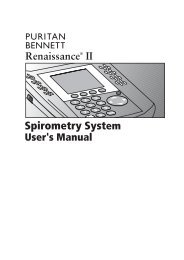
1.0 Theory of Operation1.1 IntroductionThis patient monitor is intended to be used for monitoring, displaying, reviewing, storing,and transferring of multiple physiological parameters including: ECG, respiration (Resp),temperature (Temp), SpO 2 , pulse rate (PR), non-invasive blood pressure (NIBP), invasiveblood pressure (IBP), End tidal CO 2 value (EtCO 2 ) and anesthetic gas (AG) of single adult,pediatric, and neonatal patients.FIGURE 1-1 The Passport V MonitorPassport V <strong>Service</strong> <strong>Manual</strong> 0070-10-0705 1 - 1
System ConnectionsTheory of OperationAdditional Passport V features:• Provides audible and visual alarm indications.• Incorporates multiple input devices such as a keypad and knob.• Enables program upgrade over the network.1.2 System Connections1.2.1 Mounting the Patient MonitorThe Passport V can be mounted on a wall mount bracket, a rolling stand, or a bedrailhook, which can be ordered optionally. Each type of mounting solution is delivered with acomplete set of mounting hardware and instructions. Refer to the documentation deliveredwith the mounting hardware for instructions on assembling mounts.1.2.2 Connectors for Peripheral DevicesOn the back of the Passport V are the connectors for peripheral devices.FIGURE 1-2 Connectors for Peripheral Devices1 - 2 0070-10-0705 Passport V <strong>Service</strong> <strong>Manual</strong>
Theory of OperationMain Unit1.3 Main Unit1. Auxiliary OutputA standard BNC connector, through which defibrillator synchronization signals, analogoutput signals, and nurse call signals can be outputted, depending on how the monitor isconfigured.2. SB ConnectorA connector for an external storage device.3. VGA ConnectorA connector for a standard SVGA color monitor.4. Network ConnectorAn RJ45 connector, through which an Ethernet network or a PC can be connected.5. RS232 serial portA DB9 connector, used to connect a PC for data or a Gas Module 3, depending on howthe monitor is configured.6. RS232 serial portA DB9 connector, used to connect a PC for data or a Gas Module 3, depending on howthe monitor is configured.7. AC Power ConnectorA connector for an AC power source (100 to 240 VAC, 50/60Hz).8. Equipotential lugA connector for common ground with other equipment.The Passport V consists of the following:• Input system:keypad, knob, and power switch.• Output system:LCD panel, alarm LED board, recorder, speaker, AC/battery status LEDs).• Processing and communications system:CPU board, Power management and interface board.• Power management system:battery, battery interface board, power board (AC/DC), Power management andinterface board.• Equipment interface system:power management and interface board, Ethernet-wireless adapter.• Parameter modules:multi-parameter board, CO 2 module, OEM SpO 2 module, NIBP module.Additionally, the patient monitor can also connect a DPM SB storage device, a GasModule 3, or a PC for data transfer.Passport V <strong>Service</strong> <strong>Manual</strong> 0070-10-0705 1 - 3
Theory of OperationMain UnitAlarm LampThe monitor has an alarm lamp on the front panel. The alarm LED board converts the electricsignals into visual signals and then sends the visual signals to the alarm lamp through a lightpipe. The alarm lamp illuminates either red or yellow, depending on how the alarm isconfigured.RecorderThe recorder receives data coming from the CPU board through a UART and then sends themto the thermal print head for printing. The recorder has a hard key (starting/stoppingrecordings) and a green LED on its front. It connects to the power management and interfaceboard.The following diagram shows its operating principle.MAIN BOARDRECORDERKEY BOARDPOWERSUPPLYINTERFACESIGNALINTERFACEKEY & LEDINTERFACEPOWERMODULEPOWERSUPPLYCONTROLCPUMOTORCONTROLDRIVECIRCUITFPC INTERFACETHERMAL PRINT HEADFIGURE 1-4 Operating principleMODULEPower supply interfacePower moduleCPUSignal interfaceDrive circuitRecorder key boardFPC interfaceDESCRIPTIONIntroduces a DC from the CPU board.Converts the input power into voltages that fit each module andthen forwards them to each module.Controls the communications between modules.Controls the communications between the CPU board and therecorder CPU.Receives control signals from the CPU and then forwards them tothe stepper motor.Sends key commands to the CPU and receives commands fromthe CPU to control the LED on the recorder.Sends the thermal print head information to the CPU andreceives commands from the CPU to control the thermal printhead.Passport V <strong>Service</strong> <strong>Manual</strong> 0070-10-0705 1 - 5
Main UnitTheory of OperationSpeakerThe speaker provides sound for alarms, key strokes, heart beats, pulse, and so on. It is drivendirectly by the CPU board.AC and battery status LEDsThe AC status LED and the battery status LED, located at the keypad, are controlled by theMCU on the power management and interface board. The driving signals come from thepower management and interface board and then go to the keypad via the CPU board.1.3.3 Processing and Communications SystemCPU boardThe CPU board is the heart of the patient monitor. It implements a series of tasks includinginput and output control, data storage and processing, display processing, system control,communication management, print management, alarming, etc.The CPU board has a CPU system comprising the CPU, FLASH, memory, real-time clock,EEPROM, FPGA, etc. Among them, FPGA deals with audio, video, and interfacing signals.Also, it provides interfaces to other boards, modules, and devices.Connections and communications with other components are implemented via the CPUboard, which provides interfaces to:• A built-in display• The power management and interface board. Between this board and the CPU board,the signals of USB+Network+UART+SVGA+I2C+Speaker+GPIO are communicated.Among them, UART signals finally go to the parameter boards.• The keypad. Between the keypad and the CPU board, there are two signal wires: one isthe UART signal wire and another is the AC power and battery status signal wire.• The alarm LED boardPower management and interface boardThe power management and interface board is a multi-functional board. It transmits UARTsignals to several boards and modules (e.g., multi-parameter board, CO 2 module, OEMSpO 2 module, NIBP module, recorder module, etc.).1.3.4 Power Management SystemBatteryThe monitor uses two rechargeable lithium-ion batteries (11.1 V, 4400 mAh). The batterycompartment door is located at the left-bottom of the patient monitor. The battery power isintroduced to the power module via the battery interface board, and then processed anddistributed to each component by the power management and interface board.Battery interface boardThe battery interface board serves as an interface between the batteries and the powermanagement and interface board.1 - 6 0070-10-0705 Passport V <strong>Service</strong> <strong>Manual</strong>
Theory of OperationMain UnitPower board (AC/DC)The power board (AC/DC) converts the input AC power to DC power (16.8V DC), whichthen serves as the input of the power management and interface board.Power management and interface boardThis board is responsible for power management and interfaces. Power management canperform the functions below:1. Auto-select the DC source between the power board and the two batteries.2. Convert the DC source into 12V, 5V, and 3.3V DC and then output them to other boardsand modules.3. Provide over-voltage and under-voltage protection for 12V, 5V, and 3.3V DC.4. Detect the power switch status and control power on/off.5. Detect the battery capacity and control battery charge/discharge.6. Control the LED for battery and AC status.7. Control the fan and detect its running status (the complex control algorithm isimplemented via the CPU board).8. Detect the internal temperature of the patient monitor.On this board there are four sub-boards: 3.3V and 5V DC board, 12V DC board, and twobattery charge boards. The 3.3V and 5V DC board converts the DC source into 5V and3.3V. The 12V DC board converts the DC source into 12V DC. Both of them have an overcurrentprotection mechanism. Each of the two battery charge boards controls the chargingof a battery.The DC power system is illustrated below:Powerboard(AC/DC)16.8VBatteryinterfaceboard11.1VPower managementand interface boardDC sourceauto-select16.8V/11.1V3.3VDC/DC5VDC/DC12VDC/DC3.3V5V12VCPUboarddigital circuitKnobNIBPAlarmindicatorMulti-ParameterboardInterfaceboarddigital circuitCF controlboardOEM SpO2moduleLCD digitalcircuitRecorderWirelessAdapterCO2moduleBacklightboardFIGURE 1-5 DC power systemPassport V <strong>Service</strong> <strong>Manual</strong> 0070-10-0705 1 - 7
Main UnitTheory of Operation1.3.5 Equipment Interface SystemPower management and interface boardThis board is also responsible for digital interfaces.A USB HUB is located at the board. It receives USB signals from the CPU and then distributesthem to three USB ports, of which two connect the USB sockets, and the other connects theCF control board.FIGURE 1-6 The USB hubThis board provides connections for both wired network and wireless adapter. In the figurebelow, switch 2 always stays off during normal use. The operator can switch between wirednetwork and wireless adapter through the software UI. Then, the CPU applies the operator’sselection by controlling switch 1. In configuration mode, the CPU turns off switch 1 and thenturns on switch 2 so that the operator can connect a PC to the wired network to configure thewireless adapter.The Ethernet wireless adapter enables the patient monitor to go wireless.FIGURE 1-7 The ethernet wireless adapter1 - 8 0070-10-0705 Passport V <strong>Service</strong> <strong>Manual</strong>
Theory of OperationMain UnitThe CPU generates analog signals by controlling the DAC chip on the power managementand interface board via the I2C bus. The analog signals are transmitted to the BNC socketvia the amplifier circuit.FIGURE 1-8 The amplifier circuitThe signal r_flag from the multi-parameter board goes to the power management andinterface board. The CPU can select the source of defibrillator synchronization signals bycontrolling the output of the DAC. The signal r_flag also goes to the CPU for a self-test.Two UART interfaces (serial port 1 and serial port 2) from the CPU board are extended astwo RS232-level ports via the power management and interface board. Both interfaces canbe configured to accommodate a PC for data or an AG module.FIGURE 1-9 The serial portsPassport V <strong>Service</strong> <strong>Manual</strong> 0070-10-0705 1 - 9
Main UnitTheory of Operation1.3.6 Parameter modulesMulti-Parameter boardThe multi-parameter board incorporates multiple parameters, such as ECG, RESP, DPMSPO 2 , 2-channel IBP, TEMP, etc. Details include the following:• The multi-parameter board employs a high-speed DSP, making digital filtering, arrhythmiaanalysis, and ST analysis faster and more effective.• The DSP is in charge of 3- and 5-lead ECG monitoring, arrhythmia and ST analysis, RESPmonitoring, and communicating with the CPU board.• The multi-parameter board also employs an MCU, which supports 1-channel temperaturemeasurement, DPM SpO 2 , and 2-channel IBP measurement. The MCU transfers all themeasurement data to the DSP.• Respiration rate is monitored using the impedance method and can only be measuredwith two ECG leads.• The multi-parameter board integrates the DPM SpO 2 circuit. If a monitor is configuredwith an OEM SpO 2 module, then DPM SpO 2 functions are overridden.CO 2 Module• There are two types of CO 2 modules: DPM CO 2 and Microstream CO 2 .• The DPM CO 2 module measures the CO 2 concentration using the NDIR technology. Itperforms a zero calibration periodically to ensure accurate measurements for a longperiod of time. An appropriate compensation can be applied according to the patientenvironment, thus preventing measurements from being influenced by interfering gases.• The Microstream CO 2 module ensures that measurements will not be affected by othergases and the accuracy can be maintained without any gas compensation. Additionally,the module has a very low sample flow rate, reducing its effect on the patient and theenvironment to a minimum.OEM SpO 2 ModuleThere are two types of OEM SpO 2 modules: Masimo-2013 SpO 2 module and Nellcor SpO 2module.An isolation power board is attached to each of them and used to isolate the DC power andthe UART signal of the OEM SpO 2 modules from other circuits in the main unit. The UARTsignal comes from the CPU board and passes through the power management and interfaceboard.1 - 10 0070-10-0705 Passport V <strong>Service</strong> <strong>Manual</strong>
Theory of OperationMain UnitNIBP ModuleThe figure below shows the NIBP module parameter board diagram.CUFFPRESSURESENSORFORPROTECTPRESSURESIGNALAMPLIFIERCIRCUITSFORPROTECTOVERPRESSUREPROTECTCIRCUITWATCHDOGCPUASYCHRONOUSSERIALCOMMUNICATIONPRESSURESENSORPRESSURESIGNALAMPLIFIERCIRCUITSPRESSURESIGNALA/DCONVERTERMANIFOLDMOTOR CONTROLFEEDBACK SIGNALVALVESAND PUMPPUMP ANDVALVECONTROLCIRCUITFLASHDRAMFIGURE 1-10 The NIBP module parameter boardThe Passport V calculates NIBP values using the oscillometric method of noninvasive bloodpressure measurement. These measurements correspond to comparisons with auscultatoryvalues, measured using the fifth Korotkoff sound within ANSI/AAMI SP10 standards foraccuracy.Passport V <strong>Service</strong> <strong>Manual</strong> 0070-10-0705 1 - 11
Main UnitTheory of OperationThis page intentionally left blank.1 - 12 0070-10-0705 Passport V <strong>Service</strong> <strong>Manual</strong>
2.0 Block Diagrams2.1 IntroductionThe Block Diagrams indicate the internal organization of the instrument. The block diagrams are used togain both familiarity with the instrument and to locate malfunctioning PC boards as readily as possible.DESCRIPTIONPART NUMBERNIBP Module 6100-30-86329Masimo SpO 2 Module 6100-30-86335Nellcor SpO 2 Module 6100-30-86336Microstream CO 2 Module 6100-30-86333DPM CO 2 Module 6100-30-86334Power board(AC/DC) 9211-30-87311Alarm LED Board 9211-30-87306Battery interface board assembly 9211-30-87331Keypad OverlayKeypad6100-20-86264-XX or6100-20-86341-XX6100-20-86265-XXMain board 9211-20-87303Power management and interface board 6100-20-86294Back light board 022-000001-00LCD Display 0000-10-11092Recorder 6101-30-46619Wireless AP Module 6100-30-86332CF card assembly 6100-30-86330Power Switch with Cable Assembly 6100-21-86306Speaker 020-000001-00Fan Assembly 6100-21-86315NOTE:See Isometric Drawings and Parts List for a complete list ofPart Numbers.Passport V <strong>Service</strong> <strong>Manual</strong> 0070-10-0705 2 - 1
3.0 Repair Information3.1 IntroductionThis chapter provides the necessary technical information to perform repairs on thePassport V. The most important prerequisites for effective troubleshooting are a thoroughunderstanding of the instrument functions as well as understanding the theory of operation.3.2 Safety PrecautionsIn the event the instrument covers are removed, observe the following warnings andguidelines.1. Do not short component leads together.2. The instrument covers must not be removed by anyone other than qualified technicalpersonnel who have received supplementary instructions regarding maintenance ofmedical equipment or have equivalent experience in this area.WARNING:WARNING:Internal Electrical Shock Hazard - This unit does not containany user-serviceable parts. Do not remove instrumentcovers. Refer Servicing to qualified personnel.Whenever the monitor is opened for calibration or repair, arisk (leakage) current safety check and a verification ofbasic functions of all parameters should be performedbefore the monitor is returned to Clinical use. See“Verification” on page 5-12.Passport V <strong>Service</strong> <strong>Manual</strong> 0070-10-0705 3 - 1
Troubleshooting GuidelinesRepair Information3.3 Troubleshooting Guidelines1. Identify the problemDue to the wide variety of potential symptoms, certain problems may be more subtlethan others. One approach to troubleshooting is to set up the instrument as described inChapter 5.0. Following the guidelines of the tests will help determine the problem if oneexists.2. Avoid shorting component leadsDuring repair procedures, it can become tempting to make a series of quickmeasurements. Always turn the power off before connecting and disconnecting the testleads and probes. The accidental shorting of leads can easily stress the components andcause a second failure (aside from the safety risk).3. Use the Proper equipmentThe equipment listed below is suggested to fulfill a wide range of troubleshootingrequirements. It is imperative to use the designated equipment in order to ensure properresults of any and all test procedures.4. Clean up the repair areaAfter any repair, especially after any soldering or desoldering, clean off the repair areawith alcohol and a stiff brush. This will remove any residual solder flux, in turn allowingthe instrument to return to its original appearance.3.4 Special Tools Required• Digital Voltmeter• Digital Mercury Manometer – 0 to 300 mmHg• Safety Analyzer• Patient Simulator• Test Chamber / Dummy Cuff (P/N 0138-00-0001-01 (700 cc) or -03 (500 cc))• Desktop PC or notebook PC.• Microsoft Windows 2000/XP operating system• Intel Pentium CPU, above 500MHz• Above 128M memory• At least one network card and at least one USB port• CAT-5 crossover cable• USB cable or DPM SB storage device3.5 Disassembly InstructionsBefore disassembling the unit, perform the following:• Power down the unit and remove the line cord.• Remove all cable assemblies from the left side, right side, and rear of the unit.• Remove any batteries that were installed.• Perform all work on a properly grounded ESD workstation.3 - 2 0070-10-0705 Passport V <strong>Service</strong> <strong>Manual</strong>
Repair InformationDisassembly Instructions3.5.1 Removal of the Key Panel and Keys1. Place the unit on a protective surface.2. Carefully remove the knob with a pair of pliers that have protection on the jaws. Somepliers may damage the knob.FIGURE 3-1 Remove the knob3. Release the key panel’s four clips from the bottom of the unit with a flat-bladedscrewdriver.FIGURE 3-2 Release the key panel clips4. Remove the key panel from the front.5. Remove the keys and place to the side with the key panel.Passport V <strong>Service</strong> <strong>Manual</strong> 0070-10-0705 3 - 3
Disassembly InstructionsRepair Information3.5.2 Removal of the Front Housing Assembly1. Place the unit face down on a protective surface.2. Remove the six screws from the rear of the unit.FIGURE 3-3 Remove the screws from the rear of the unit3. Turn the unit over and carefully separate the front housing assembly and rear housingassembly.4. Disconnect the 50-pin ribbon cable from the front housing assembly.FIGURE 3-4 Disconnect the ribbon cable from the front housing assembly5. Remove the front housing assembly.3 - 4 0070-10-0705 Passport V <strong>Service</strong> <strong>Manual</strong>
Repair InformationDisassembly Instructions3.5.3 Removal of the Main Board1. Remove the front housing assembly as stated in “Removal of the Front HousingAssembly” on page 3-4.2. Remove the keyboard cable.3. Remove the inverter cable.4. Remove the LCD panel cable.5. Remove the alarm LED board cable.6. Remove the five screws that secure the main board to the front housing bracket.7. Remove the main board carefully.FIGURE 3-5 Remove the main boardPassport V <strong>Service</strong> <strong>Manual</strong> 0070-10-0705 3 - 5
Disassembly InstructionsRepair Information3.5.4 Removal of the Inverter1. Remove the front housing assembly as stated in “Removal of the Front HousingAssembly” on page 3-4.2. Remove the inverter cable.3. Remove the two backlight board cable from the inverter.4. Remove the two screws that secure the inverter to the front housing bracket.5. Remove the inverter carefully.FIGURE 3-6 Remove the inverter3 - 6 0070-10-0705 Passport V <strong>Service</strong> <strong>Manual</strong>
Repair InformationDisassembly Instructions3.5.5 Removal of the LCD Panel1. Remove the front housing assembly as stated in “Removal of the Front HousingAssembly” on page 3-4.2. Remove the two backlight board cables from the inverter.3. Remove the keyboard cable.4. Remove the alarm LED board cable.5. Remove the LCD panel cable.6. Remove the eight screws that secure the front housing bracket.7. Remove the front housing bracket and place to the side.FIGURE 3-7 Remove the LCD panelPassport V <strong>Service</strong> <strong>Manual</strong> 0070-10-0705 3 - 7
Disassembly InstructionsRepair Information8. Remove the four screws that secure the LCD panel.9. Remove the LCD panel carefully.FIGURE 3-8 Remove the LCD panel3.5.6 Removal of the Keyboard1. Remove the front housing assembly as stated in “Removal of the Front HousingAssembly” on page 3-4.2. Remove the keyboard cable.3. Remove the encoder cable.4. Remove the four screws that secure the keyboard to the front housing.5. Remove the four keyboard pads.6. Release the clip on the right side of the keyboard and remove the keyboard carefully.FIGURE 3-9 Remove the Keyboard3 - 8 0070-10-0705 Passport V <strong>Service</strong> <strong>Manual</strong>
Repair InformationDisassembly Instructions3.5.7 Removal of the Alarm LED Board1. Remove the front housing assembly as stated in “Removal of the Front HousingAssembly” on page 3-4.2. Remove the alarm LED board cable.3. Remove the two screws that secure the board to the front housing.4. Remove the alarm LED board and light conducting pipe carefully.FIGURE 3-10 Remove the alarm LED board3.5.8 Removal of the Encoder1. Remove the front housing assembly as stated in “Removal of the Front HousingAssembly” on page 3-4.2. Remove the encoder cable from the keyboard.FIGURE 3-11 Disconnect the encoder cablePassport V <strong>Service</strong> <strong>Manual</strong> 0070-10-0705 3 - 9
Disassembly InstructionsRepair Information3. Carefully remove the knob with a pair of pliers that have protection on the jaws. Somepliers may damage the knob.4. Remove the nut that secures the encoder.5. Remove the encoder carefully.FIGURE 3-12 Remove the encoder3.5.9 Removal of the Multi-parameter Board Assembly1. Remove the front housing assembly as stated in “Removal of the Front HousingAssembly” on page 3-4.2. Disconnect the 50-pin ribbon cable from the interface board.3. Disconnect the cable from J15 of the interface board.4. Disconnect the NIBP communication cable from the interface board.FIGURE 3-13 Disconnect the cables from the multi-parameter board3 - 10 0070-10-0705 Passport V <strong>Service</strong> <strong>Manual</strong>
Repair InformationDisassembly Instructions5. Remove the four screws that secure the assembly to the rear housing and main frame.6. Disconnect the CO 2 tubing and cable from the multi-parameter board assembly (if CO 2module is configured).7. Remove the multi-parameter board assembly carefully.FIGURE 3-14 Remove the multi-parameter board assemblyPassport V <strong>Service</strong> <strong>Manual</strong> 0070-10-0705 3 - 11
Disassembly InstructionsRepair Information3.5.10 Removal of the Parameter Front Panel Assembly1. Remove the multi-parameter board assembly as stated in “Removal of the MultiparameterBoard Assembly” on page 3-10.2. Unplug the tubing from the NIBP connector.FIGURE 3-15 Unplug the tubing from the NIBP connector3. Unfasten the two screws that secure the SpO 2 connector and then remove the connector(if Masimo or Nellcor SpO 2 module is configured).FIGURE 3-16 Masimo SpO 2 FIGURE 3-17 Nellcor SpO 24. Remove the three screws that secure the parameter front panel.5. Remove the parameter front panel.FIGURE 3-18 Remove the parameter front panel3 - 12 0070-10-0705 Passport V <strong>Service</strong> <strong>Manual</strong>
Repair InformationDisassembly Instructions3.5.11 Removal of the Multi-parameter board1. Remove the parameter front panel assembly as stated in “Removal of the ParameterFront Panel Assembly” on page 3-12.2. Remove the three screws that secure the multi-parameter board.3. Remove the multi-parameter board.FIGURE 3-19 Remove the multi-parameter board3.5.12 Removal of the CO 2 Module1. Remove the multi-parameter board assembly as stated in “Removal of the MultiparameterBoard Assembly” on page 3-10.2. Remove the two screws that secure the module to the main frame.3. Remove the CO 2 module.FIGURE 3-20 DPM CO 2 FIGURE 3-21 Microstream CO 24. Remove the water trap connector assembly or microstream CO 2 connector fixtureassembly from the parameter front panel assembly (if necessary).Passport V <strong>Service</strong> <strong>Manual</strong> 0070-10-0705 3 - 13
Disassembly InstructionsRepair Information3.5.13 Removal of the Masimo SpO 2 Module1. Remove the multi-parameter board assembly as stated in “Removal of the MultiparameterBoard Assembly” on page 3-10.2. Disconnect the SpO 2 communication cable from the multi-parameter board.3. Cut the tie of flexible cable.4. Unfasten the screw that secures the Masimo SpO 2 module to the multi-parameter boardinstallation frame.5. Unfasten the two screws that secure the Masimo SpO 2 connector.6. Remove the Masimo SpO 2 module.FIGURE 3-22 Remove the Masimo SpO 2 module3.5.14 Removal of the Nellcor SpO 2 Module1. Remove the multi-parameter board assembly as stated in “Removal of the MultiparameterBoard Assembly” on page 3-10.2. Disconnect the SpO 2 communication cable from the multi-parameter board.3. Cut the tie of flexible cable.4. Unfasten the screw that secures the Nellcor SpO 2 module to the multi-parameter boardinstallation frame.5. Unfasten the two screws that secure the Nellcor SpO 2 connector.6. Remove the Nellcor SpO 2 module.FIGURE 3-23 Remove the Nellcor SpO 2 module3 - 14 0070-10-0705 Passport V <strong>Service</strong> <strong>Manual</strong>
Repair InformationDisassembly Instructions3.5.15 Removal of the NIBP Assembly1. Remove the multi-parameter board assembly as stated in “Removal of the MultiparameterBoard Assembly” on page 3-10.2. Unplug the tubing from the NIBP gas nipple.3. Disconnect the NIBP communication cable from the NIBP board.4. Unfasten the screws that secure the NIBP assembly to the multi-parameter boardinstallation frame.5. Remove the NIBP assembly.FIGURE 3-24 Remove the NIBP assembly3.5.16 Removal of the Recorder Assembly1. Remove the two screws that secure the recorder.2. Release the two clips and pull out the recorder.FIGURE 3-25 Remove the recorder assembly3. Disconnect the recorder cable.4. Remove the recorder.Passport V <strong>Service</strong> <strong>Manual</strong> 0070-10-0705 3 - 15
Disassembly InstructionsRepair Information3.5.17 Removal of the Recorder Cover (if needed)1. Pry up the recorder cover with a flat-bladed screwdriver.FIGURE 3-26 Remove the recorder cover3.5.18 Removal of the Main Frame and Multi-parameter Board Assembly1. Remove the front housing assembly as stated in “Removal of the Front HousingAssembly” on page 3-4.2. Remove the recorder assembly (if installed) as stated in “Removal of the RecorderAssembly” on page 3-15.3. Disconnect the power switch cable from the interface board.4. Remove the eight screws that secure the main frame and multi-parameter boardassembly to the rear housing.FIGURE 3-27 Remove the screws and cables from the main frame3 - 16 0070-10-0705 Passport V <strong>Service</strong> <strong>Manual</strong>
Repair InformationDisassembly Instructions5. Remove the two screws that secure the main frame from the bottom.6. Remove the main frame and multi-parameter board assembly.FIGURE 3-28 Remove the main frame and multi-parameter board assembly3.5.19 Removal of the Speaker Assembly1. Remove the main frame and multi-parameter board assembly as stated in “Removal ofthe Main Frame and Multi-parameter Board Assembly” on page 3-16.2. Cut the clamp that secures the speaker cable.3. Disconnect the speaker cable from the interface board.FIGURE 3-29 Disconnect the speaker cable from the interface board4. Remove the three screws that secure the speaker.5. Remove the speaker assembly.FIGURE 3-30 Remove the speaker assemblyPassport V <strong>Service</strong> <strong>Manual</strong> 0070-10-0705 3 - 17
Disassembly InstructionsRepair Information3.5.20 Removal of the Fan Assembly1. Remove the main frame and multi-parameter board assembly as stated in “Removal ofthe Main Frame and Multi-parameter Board Assembly” on page 3-16.2. Cut the clamp that secures the fan cable.3. Disconnect the fan cable from the interface board.FIGURE 3-31 Disconnect the fan cable from the interface board4. Remove the fan EVA cushion.5. Remove the two screws that secure the fan.FIGURE 3-32 Remove the fan assembly6. Remove the fan.3 - 18 0070-10-0705 Passport V <strong>Service</strong> <strong>Manual</strong>
Repair InformationDisassembly Instructions3.5.21 Removal of the CF Card Assembly1. Remove the main frame and multi-parameter board assembly as stated in “Removal ofthe Main Frame and Multi-parameter Board Assembly” on page 3-16.2. Remove the two screws that secure the CF card assembly.3. Disconnect the CF card cable.4. Remove the CF card assembly.FIGURE 3-33 Remove the CF card assembly3.5.22 Removal of the Power Board1. Remove the main frame and multi-parameter board assembly as stated in “Removal ofthe Main Frame and Multi-parameter Board Assembly” on page 3-16.2. Remove the two screws that secure the recorder connecting board and then remove the board.FIGURE 3-34 Remove the screws securing the recorder connecting boardPassport V <strong>Service</strong> <strong>Manual</strong> 0070-10-0705 3 - 19
Disassembly InstructionsRepair Information3. Disconnect the power board connecting cable from the interface board.FIGURE 3-35 Disconnect the power board connecting cable4. Remove the three screws that secure the power socket support from the back of the mainframe.5. Remove the screw that secures the grounding wire.FIGURE 3-36 Remove the screws that secure the power socket3 - 20 0070-10-0705 Passport V <strong>Service</strong> <strong>Manual</strong>
Repair InformationDisassembly Instructions6. Disconnect the power socket cable from the power board.7. Remove the four screws that secure the power board.8. Remove the power board.FIGURE 3-37 Remove the power board3.5.23 Removal of the Li-ion Battery Interface Board Assembly1. Remove the front housing assembly as stated in “Removal of the Front HousingAssembly” on page 3-4.2. Remove the recorder assembly (if installed) as stated in “Removal of the RecorderAssembly” on page 3-15.3. Remove the two screws that secure the recorder connecting board and then remove theboard.FIGURE 3-38 Remove the screws securing the recorder connecting boardPassport V <strong>Service</strong> <strong>Manual</strong> 0070-10-0705 3 - 21
Disassembly InstructionsRepair Information4. Disconnect the Li-ion battery interface board cable from the interface board.FIGURE 3-39 Disconnect the Li-ion battery interface board cable5. Remove the four nuts that secure the Li-ion battery interface board assembly.6. Remove the Li-ion battery interface board assembly.FIGURE 3-40 remove the Li-ion battery interface board assembly3 - 22 0070-10-0705 Passport V <strong>Service</strong> <strong>Manual</strong>
Repair InformationDisassembly Instructions3.5.24 Removal of the Interface Board Assembly1. Remove the multi-parameter board assembly as stated in “Removal of the MultiparameterBoard Assembly” on page 3-10.2. Remove the recorder assembly (if installed) as stated in “Removal of the RecorderAssembly” on page 3-15.3. Disconnect the power switch cable from the interface board.4. Remove the six screws that secure the main frame to the rear housing.FIGURE 3-41 Remove the screws from the main frame5. Remove the two screws that secure the main frame from the bottom.6. Remove the main frame assembly and place to the side.FIGURE 3-42 Remove the screws securing the main frame7. Disconnect the Li-ion battery interface board cable from the interface board.8. Disconnect the power cable from the interface board.9. Disconnect the recorder cable from the interface board.Passport V <strong>Service</strong> <strong>Manual</strong> 0070-10-0705 3 - 23
Disassembly InstructionsRepair InformationFIGURE 3-43 Disconnect the cables from the interface board10. Disconnect the speaker cable from the interface board.11. Disconnect the fan cable from the interface board.12. Disconnect the CF card cable from the interface board.13. Disconnect the wireless AP (if installed) cable from the interface board.FIGURE 3-44 Disconnect the cables from the interface board14. Remove the two screws that secure the interface board assembly to the main frame.15. Remove the interface board assembly.FIGURE 3-45 Remove the interface board assembly3 - 24 0070-10-0705 Passport V <strong>Service</strong> <strong>Manual</strong>
Repair InformationDisassembly Instructions3.5.25 Removal of the Wireless AP1. Remove the multi-parameter board assembly as stated in “Removal of the MultiparameterBoard Assembly” on page 3-10.2. Remove the recorder assembly (if installed) as stated in “Removal of the RecorderAssembly” on page 3-15.3. Disconnect the power switch cable from the interface board.4. Remove the six screws that secure the main frame to the rear housing.FIGURE 3-46 Remove the screws from the main frame5. Remove the two screws that secure the main frame from the bottom.6. Remove the main frame assembly.FIGURE 3-47 Remove the screws securing the main framePassport V <strong>Service</strong> <strong>Manual</strong> 0070-10-0705 3 - 25
Disassembly InstructionsRepair Information7. Remove the nut that secures the wireless AP to the main frame.FIGURE 3-48 Remove the nut securing the wireless AP to the main frame8. Disconnect the wireless AP cable from the wireless AP.9. Remove the wireless AP.FIGURE 3-49 Disconnect the cables from the wireless AP3 - 26 0070-10-0705 Passport V <strong>Service</strong> <strong>Manual</strong>
Repair InformationNurse Call Cable3.6 Nurse Call Cable3.6.1 P/N 8000-21-10361FIGURE 3-50 Nurse Call Cable3.7 Analog Output Cable3.7.1 P/N 6100-20-86360FIGURE 3-51 Analog Output CablePassport V <strong>Service</strong> <strong>Manual</strong> 0070-10-0705 3 - 27
Defib Synch CableRepair Information3.8 Defib Synch Cable3.8.1 P/N 6100-20-86361FIGURE 3-52 Defib Synch Cable3 - 28 0070-10-0705 Passport V <strong>Service</strong> <strong>Manual</strong>
Null Modem CableRepair Information3.10 Null Modem Cable3.10.1 P/N 0012-00-1275-01FIGURE 3-54 Null Modem Cable3 - 30 0070-10-0705 Passport V <strong>Service</strong> <strong>Manual</strong>
Repair InformationUniversal ECG Lead Wires3.11 Universal ECG Lead Wires3.11.1 P/N 0012-00-1503-XXDESCRIPTION DASH #10 24", snap, 5-lead set, Domestic -0211 24", snap, 3-lead set, Domestic -0512 24", snap, 5-lead set, International -1113 24", snap, 3-lead set, International -14FIGURE 3-55 Universal ECG Lead WiresPassport V <strong>Service</strong> <strong>Manual</strong> 0070-10-0705 3 - 31
ECG Cable, 3/5-lead (ESIS and Non ESIS)Repair Information3.12 ECG Cable, 3/5-lead (ESIS and Non ESIS)3.12.1 P/N 0012-00-1745-XXFIGURE 3-56 ECG Cable, 3/5-lead (ESIS and Non ESIS)3.13 12-pin 3-lead Neo ECG Trunk Cable (IEC/AHA)3.13.1 P/N 040-000072-00FIGURE 3-57 12-pin 3-lead Neo ECG Trunk Cable (IEC/AHA)3 - 32 0070-10-0705 Passport V <strong>Service</strong> <strong>Manual</strong>
Repair InformationIBP Cable3.14 IBP Cable3.14.1 P/N 040-000052-00FIGURE 3-58 5-pin IBP Cable (IM2301, Hospira)3.14.2 P/N 040-000053-00FIGURE 3-59 5-pin IBP Cable (IM2302, BD)3.14.3 P/N 040-000054-00FIGURE 3-60 5-pin IBP Cable (IM2303, Edwards)Passport V <strong>Service</strong> <strong>Manual</strong> 0070-10-0705 3 - 33
Temperature CableRepair Information3.14.4 P/N 040-000096-00FIGURE 3-61 IBP Adapter Cable (5-pin to 6-pin)3.15 Temperature Cable3.15.1 1.15.1 P/N 040-000055-00FIGURE 3-62 5-pin Esophageal/Rectal Temp Probe (Adult)3.15.2 P/N 040-000056-00FIGURE 3-63 5-pin Esophageal/Rectal Temp Probe (Pediatric/Infant)3 - 34 0070-10-0705 Passport V <strong>Service</strong> <strong>Manual</strong>
Repair InformationTemperature Cable3.15.3 P/N 040-000057-00FIGURE 3-64 5-pin Skin Temp Probe (Adult)3.15.4 P/N 040-000058-00FIGURE 3-65 5-pin Skin Temp Probe (Pediatric/Infant)3.15.5 P/N 040-000091-00FIGURE 3-66 5-pin Temp Cable for 400 Series Disposable SensorPassport V <strong>Service</strong> <strong>Manual</strong> 0070-10-0705 3 - 35
Temperature CableRepair Information3.15.6 P/N 040-0000100-00FIGURE 3-67 5-pin Temp Adapter Cable (5-pin to 6.35 Phone)3.15.7 P/N 040-000224-00FIGURE 3-68 5-pin Temp Cable for MRS Disposable Sensor (5.5 DC Jack)3 - 36 0070-10-0705 Passport V <strong>Service</strong> <strong>Manual</strong>
Repair InformationTroubleshooting Menus3.16 Troubleshooting Menus3.16.1 ECG TroubleshootingMESSAGE/PROBLEM REASON SOLUTIONNoisy ECG traces 1 Loose or dry electrodes.2 Defective electrode wires.3 Patient cable or leads arerouted too close to otherelectrical devices.Excessive Electro-surgicalInterference1 Apply fresh, moistelectrodes.2 Replace wires asnecessary.3 Eliminate 60Hzinterference.1 Wrong ECG cable used. 1 Use ESIS ECG cable withinternal filter block.Muscle Noise 1 Inadequate skinpreparation prior toapplication of electrode,tremors, tense subject,and/or poor electrodeplacement.Excessive alarms: heart rate,lead fault1 Electrodes dry2 Alarm limits set too closeto patient's normal heartrate.3 R-wave wrong size.4 Excessive patientmovement or muscletremor.ECG Noise 1 External interference.2 Patient movement.No ECG Waveform 1 Gain set too low.2 Lead wires and patientcable not fully or properlyinserted.3 Cable or lead wiresdamaged.NOTE: Respirationmonitoring via theECG electrodes willnot be availablewhen using an ESISECG cable.1 Repeat skin preparationand electrode locationprocedures.2 Apply fresh, moistelectrodes.3 Avoid areas of the torsothat are very muscular.1 Re-prep skin and applyfresh, moist electrodes.2 Readjust.3 Must have a higheramplitude than the otherECG waves, like the Pand T waves.4 Reposition electrodes andsecure with tape, ifnecessary.1 Check patient.2 Check electrode contacts/reposition electrodes/cable.3 Check environment forsource of interference.1 Readjust as required (Setvia the Size key).2 Check for properinsertion.3 Check with leadcontinuity tester.Passport V <strong>Service</strong> <strong>Manual</strong> 0070-10-0705 3 - 37
Troubleshooting MenusRepair InformationMESSAGE/PROBLEM REASON SOLUTIONBase Line Wander 1 Patient movingexcessively.2 Patient's respiration.Electrodes dry or loose.3 Static build up aroundpatient.4 ECG Filter set to “ST” or“Diagnose” mode.ECG Artifact 1 Electrical interferencefrom auxiliary devices.2 Patient movement.Self Test Error 1 During power-on of theunit, if ECG module cannot self-test successfully,this message will display.Communication Stop 1 As the ECG modulecommunication stops, thedata packets sent by themodule can not bereceived.Communication Error 1 The ECG modulecommunication error. Thecommand can not be sentcorrectly.ESU-Resp Off 1 The high frequencyelectrosurgery unitinterference signal isdetected.ECG Signal Invalid 1 Connections not tight orproperly secured.2 Electrodes dry or loose.3 Cable or lead wiresdamaged.Pacer Rejection On 1 When Pacer Reject is setto On.Learning 1 Displayed when alearning cycle has beenrequested for Arrhythmiaor ST.No Arrhythmia Detection atCentral1 Central Station does nothave arrhythmia Analysiscapability.1 Secure lead wires andcable to patient.2 Reposition electrodes.3 Re-prep skin and applyfresh, moist electrodes.4 Check with localbiomedical personnel.5 Set ECG Filter to“Monitor” mode.1 Check patient.2 Check Electrode Contacts/reposition electrodes/cable.3 Check for electricalinterference, replacewires as necessary.1 Power cycle unit. Ifmessage reappears,contact TechnicalSupport.1 Contact TechnicalSupport.1 Contact TechnicalSupport.1 Wait until the highfrequency electrosurgeryunit interferencedisappears.1 Ensure properconnection. (Electrode tolead, lead to cable, cableto monitor).2 Re-prep skin and applyfresh, moist electrodes.3 Check with continuitytester.1 This is normal operation.When Pace Reject is setto Off, this messagedisappears.//3 - 38 0070-10-0705 Passport V <strong>Service</strong> <strong>Manual</strong>
Repair InformationTroubleshooting MenusMESSAGE/PROBLEM REASON SOLUTIONECG Channels Checking... 1 Appears when the ECGModule is calibrating.Initialization Error 1 During the ECG modulepower-on, as the ECGmodule communicationstops, system fails tocommunicate withmodule.3.16.2 NIBP Troubleshooting1 This is normal operation.Turn off ECG modulecalibration and themessage will be cleared.1 Contact TechnicalSupport.MESSAGE/ PROBLEM REASON SOLUTIONNIBP: Self Test Error 1 Failed self-test.2 Sensor or A/D samplingmay have error.NIBP: Communication Error 1 NIBP modulecommunication error. Thecommand can not be sentcorrectly.NIBP: System Error 1 System error. After startup,the inflating pump,A/D sampling unit orpressure sensor may haveerror or the pointer mayhave error when thesoftware is running.2 Power supply is not stableor circuit failure leads tovoltage error.NIBP: Cuff Overpressure 1 The hardwareoverpressure limit hasbeen exceeded.2 Overpressure. The cuffpressure exceeds 297mmHg in ADU mode,240 mmHg in PED modeor 147 mmHg in NEOmode.NIBP: Pneumatic Leak 1 Leakage. In Pneumaticcheck, air leakage isfound in hose.NIBP: Unable to Measure 1 Unable to makemeasurement after threeautomatic retries.1 Power cycle unit. Ifmessage reappears,contact TechnicalSupport.1 Power cycle unit. Ifmessage reappears,contact TechnicalSupport.1 Power cycle unit. Ifmessage reappears,contact TechnicalSupport.1 Power cycle unit.Ifmessage reappears,contact TechnicalSupport.1 Change the cuff.1 Check Patient.2 Retry measurement. Ifmessage reappears,power cycle unit. Ifmessage reappears,contact TechnicalSupport.NIBP: Reset Failed 1 Reset failed. 1 Power cycle unit.Ifmessage reappears,contact TechnicalSupport.Passport V <strong>Service</strong> <strong>Manual</strong> 0070-10-0705 3 - 39
Troubleshooting MenusRepair InformationMESSAGE/ PROBLEM REASON SOLUTIONNIBP: Retry Pump Higher 1 A measurement has beenattempted but no readingwas possible. This resultsfrom inadequate cuffinflation pressure.NIBP: Retry 1 Cuff is loosely wrapped.The cuff may be tooloosely wrapped or notattached at all.2 Weak signal. The pulse ofthe patient may be tooweak or the cuff is looselywrapped.3 Excessive motion. Inmeasurement, signalscontain motion artifact ortoo much interference.4 Time-out. Measurementtakes more than 120seconds in ADU/PEDmode and 90 seconds inNEO mode.5 Retry Overpressure orbad measurement.NIBP: Initialization Error 1 During the IBP modulepower-on, as the IBPmodule communicationstops, system fails tocommunicate withmodule.NIBP: Communication Stop 1 As the Resp modulecommunication stops, thedata packets sent by themodule can not bereceived.3.16.3 SpO 2 Troubleshooting1 Retry will be attempted.2 Check that appropriatepatient size is set.3 Pre-set initial inflationpressure.1 Retry will be attempted.Check for leaks andquality of peripheralpulses. Decrease patientmovement. Switch cuff toanother limb.1 Contact TechnicalSupport.1 Contact TechnicalSupport.MESSAGE/ PROBLEM REASON SOLUTIONSpO 2 : No Sensor 1 Sensor is not plugged into the monitor.SpO 2 : Sensor Off 1 Sensor may not beconnected to the patient.SpO 2 : Interference(Masimo/Nellcor Only)1 Noise detected on thepulse signal preventspulse discrimination.SpO 2 : Pulse Search 1 Hardware settings arebeing adjusted in order todiscriminate a pulsewaveform.SpO 2 : No Pulse (DPM/NellcorOnly)1 No detectable pulse ismeasured.1 Plug the sensor into themonitor.1 Check patient connection.1 Decrease patient motion,check sensor.1 Change to site wherepulse is stronger if patientis vasoconstricted.2 Change or readjustsensor if loose.1 Check to patientconnection and patientstatus.3 - 40 0070-10-0705 Passport V <strong>Service</strong> <strong>Manual</strong>
Repair InformationTroubleshooting MenusMESSAGE/ PROBLEM REASON SOLUTIONSpO 2 : Failure 1 The system has detectedan unrecoverable failureof the SpO 2 system.SpO 2 : Low Perfusion(Masimo/DPM only)SpO 2 : Too Much Light(Masimo/DPM only)SpO 2 : Unrecognized Sensor(Masimo SET Only)1 Power cycle unit. Ifmessage reappears,contact TechnicalSupport.1 Patient perfusion is low. 1 Check to patientconnection and patientstatus.1 There is too muchambient room light for thesensor to functionproperly.1 The monitor does notrecognize the sensor.SpO 2 : Communication Error 1 The monitor and theSpO 2 modules are notcommunicating properly.SpO 2 : Board Fault(Masimo Only)1 Masimo SET board failedto operate properly.1 Minimize the room lightaround the patient. Checksensor.1 Replace the sensor with arecommended sensor.1 Power cycle unit. Ifproblem persists, contactTechnical Support.1 See Proper <strong>Service</strong> Menu:Suggestion.SpO 2 : Sensor Fault 1 Defective Sensor. 1 Replace Sensor.SpO 2 : Motion(Nellcor Only)SpO 2 : Weak Pulse(Nellcor Only)SpO 2 : Low Signal(Nellcor Only)SpO 2 : Check Sensor(Nellcor Only)SpO 2 : Weak Signal(Nellcor Only)Unable to obtain SpO 2reading1 Motion is detected. 1 Decrease patient motion,check sensor.1 Low pulse amplitude. 1 Contact TechnicalSupport.1 The SpO 2 signal is toolow or too weak.1 The SpO 2 module hassensed a poor connectionor a bad sensor.1 The SpO 2 signal is toolow or too weak.1 Patient has poorperfusion. Sensor not onPatient.2 Cables loose / notconnected.3 Ambient light.No SpO 2 waveform 1 Waveform not selected toDisplay.2 Cable or sensor notplugged in.SpO 2 : Initialization Error 1 No response after sendorder duringinitialization.1 Check sensor placement,move as necessary.2 Switch limb / Notifyphysician.1 Reconnect the samesensor. If problempersists, replace sensor.1 Check patient.2 Reposition sensor.3 Change sensor.1 Switch limbs / Notifyphysician.2 Reapply sensor.3 Check connections,switch cable.4 Switch limbs and coversensor with opaquematerial.1 Go to the Display SetupMenu, choose to displayPleth in the waveformarea.2 Check cable and sensor.1 Contact TechnicalSupport.Passport V <strong>Service</strong> <strong>Manual</strong> 0070-10-0705 3 - 41
Troubleshooting MenusRepair InformationMESSAGE/ PROBLEM REASON SOLUTIONSpO 2 : Communication Error 1 The monitor and theSpO 2 modules are notcommunicating properly.SpO 2 : Communication Stop 1 As the SpO 2 modulecommunication stops, thedata packets sent by theSpO 2 module can not bereceived.3.16.4 Temperature Troubleshooting1 Contact TechnicalSupport.1 Contact TechnicalSupport.MESSAGE/ PROBLEM REASON SOLUTIONTemperature Probes notWorking1 Poor contact from probesto body.Temperature not displayed 1 Improper display setup.2 Cable not plugged in.Temp: Communication Stop 1 As the Temp modulecommunication stops, thedata packets sent by theTemp module can not bereceived.Temp: Communication Error 1 Temp modulecommunication error. Thecommand can not besend correctly.Temp: SelfTest Error 1 Module sends out errorduring selftest because ofsome unspecifiedreasons.1 Check the body surfacecontact at the probe tip.2 Reposition or applythermoconductive gel.1 Check display setup inMonitor Setup Menu andchange as desired.2 Check the cable.1 Contact TechnicalSupport.1 Contact TechnicalSupport.1 Contact TechnicalSupport.Temp: Calibration Error 1 A calibration failed. 1 Restart the monitor.2 Contact TechnicalSupport.Temp: Initialization Error 1 During the Temperaturemodule power-on, as theTemperature modulecommunication stops,system fails tocommunicate withmodule.1 Contact TechnicalSupport.3 - 42 0070-10-0705 Passport V <strong>Service</strong> <strong>Manual</strong>
Repair InformationTroubleshooting Menus3.16.5 Resp TroubleshootingMESSAGE/ PROBLEM REASON SOLUTIONResp. Waveform Too Large 1 Scales setinappropriately.Resp. Waveform Too Small 1 Patient breathing isshallow or patient isturned on side.Scale setinappropriately.False Apnea Alarm 1 Apnea delay may beimproperly set.2 Patient may be havingfrequent episodes of CVA.3 Scale size may be toolow.No Resp. Waveform or RateDisplayed1 Respiration turned Off.2 Patient connected usingESIS choke cable.3 Cable not connected.“CHK Lead” Message 1 Increased impedancecaused by one of thefollowing:2 Chest hair underelectrodes.3 Dried electrode gel.4 Electrode off. Lead off.5 Cracked lead wires.6 Poor skin prep.Resp high impedance 1 Connections not tightand/or properly secured.2 Electrodes dry or loose.3 Cable or lead wiresdamaged.“CVA” Message 1 Can be caused byshallow breathing or anapnea event.2 Patient HR andrespiratory rate identical.Resp: Initialization Error 1 During the Resp modulepower-on, as the Respmodule communicationstops, system fails tocommunicate withmodule.1 Change lead selection.2 Change Respirationscale.1 Change lead selection.2 Change respiration scale.1 Choose another apneadelay.2 Reposition electrodes tobetter detect respirations.3 Change Respirationscale.1 Turn respiration On (Offwill be displayed in Resp.window).2 Check that proper patientcable is used. Use nonESIS patient cable.3 Check cable.1 Prep chest.2 Change electrodes.3 Replace electrode.4 Replace lead.5 Replace lead wires.6 Clean and abrade skinbefore applyingelectrodes.1 Ensure properconnection. (Electrode tolead, lead to cable, cableto monitor).2 Re-prep skin and applyfresh, moist electrodes.3 Check with continuitytester.1 Check the patient.2 Adjust scales or leads ifnecessary. Check thepatient.1 Contact TechnicalSupport.Passport V <strong>Service</strong> <strong>Manual</strong> 0070-10-0705 3 - 43
Troubleshooting MenusRepair InformationMESSAGE/ PROBLEM REASON SOLUTIONResp: Communication Error 1 System cannotcommunicate correctlywith Resp module, andreceive the error datapackets.Resp: Communication Stop 1 As the Resp modulecommunication stops, thedata packets sent by themodule can not bereceived.3.16.6 IBP Troubleshooting1 Restart the monitor. If theerror still appears, pleasecontact TechnicalSupport.1 Contact TechnicalSupport.MESSAGE/ PROBLEM REASON SOLUTIONDamped Invasive Waveform 1 Air bubbles in tubing.2 Kinked catheter.3 Catheter against wall ofblood vessel.4 Blood in tubing5 Catheter partiallyoccluded with clot.IBP not Displayed / No IBPWaveformAbnormally High or Lowreadings1 Improper Setup.2 Cable not plugged in3 Transducer notconnected.4 Stopcock turnedimproperly.5 Transducer not zeroed.1 Transducer too HIGH ortoo LOW.Sensor Off 1 The IBP sensordisconnected from thepatient or the monitor.Sensor Off. Cannot Zero! 1 Sensor Off. And can notzero IBP channel.Pulsatile Pressure. CannotZero!Pressure Overrange. CannotZero!1 Input the pulsatilepressure, can not zero IBPchannel.1 The pressure isoverrange, can not zeroIBP channel.Initialization Error 1 During the IBP modulepower-on, as the IBPmodule communicationstops, system fails tocommunicate withmodule.1 Eliminate air from tubing.2 Change position ofcatheter, check patient.3 Check for leaks atconnector, flush catheter.4 Pump pressure bag up to300 mmHg.5 Consult physician.1 Check display setup inmonitor setup.2 Check cable.3 Check transducerconnection.4 Check transducer.5 Check and zero thetransducer.1 Check patient adjusttransducer, re-zero.1 Reconnect sensor, re-zeroIBP channel.1 Reconnect sensor, re-zeroIBP channel.1 Input the static pressure,re-zero IBP channel.1 Check the static pressurevalue, re-zero IBPchannel.1 Contact TechnicalSupport.3 - 44 0070-10-0705 Passport V <strong>Service</strong> <strong>Manual</strong>
Repair InformationTroubleshooting MenusMESSAGE/ PROBLEM REASON SOLUTIONCommunication Error 1 IBP communication error.The command can not besend correctly.Communication Stop 1 As the IBP modulecommunication stops, thedata packets sent by theIBP module can not bereceived.3.16.7 CO 2 Troubleshooting1 Power cycle unit. Ifmessage reappears,contact TechnicalSupport.1 Power cycle unit. Ifmessage reappears,contact TechnicalSupport.MESSAGE/ PROBLEM REASON SOLUTIONCO 2 : Check Flow Rate(Microstream only)CO 2 : Filtering Disconnected(Microstream only)CO 2 : Purge(Microstream only)CO 2 : Occlusion(Microstream only)CO 2 : Sensor High Temperature(DPM only)CO 2 : Sensor Low Temperature(DPM only)CO 2 : High Airway Press.(DPM only)CO 2 : Low Airway Press.(DPM only)CO 2 : High Barometric(DPM only)1 The system has detected ahigh or low flow rate.1 Check Filterline andreplace if necessary.1 Filtering disconnected. 1 Connect Filterline tomonitor.1 Sample line is blocked orkinked.1 Sample line is blocked orkinked.1 Temperature over rangeshigh limit checked bymodule.1 Temperature over rangeslow limit checked bymodule.1 Measurement of FluxSensor in module ishigher than 790 mmHg.1 Measurement of FluxSensor in module is lessthan 400 mmHg.1 Atmospheric pressure istoo high (higher than790mmHg).1 Check sample line. Clearblockage or kink orreplace with a newsample line.1 Check sample line. Clearblockage or kink orreplace with a newsample line.1 Check, stop using orreplace the sensor.1 Check, stop using orreplace the sensor.1 Check airway's outputand connection.2 If problems remain, returnit to factory formaintaining.1 Check airway's outputand connection.2 If problems remain exist,return it to factory formaintaining.1 Check the CO 2connections, make surethat the monitorapplication site meets therequirements, and checkfor special sources thataffect the ambientpressure.2 Restart the monitor.Passport V <strong>Service</strong> <strong>Manual</strong> 0070-10-0705 3 - 45
Troubleshooting MenusRepair InformationMESSAGE/ PROBLEM REASON SOLUTIONCO 2 : Low Barometric(DPM only)CO 2 : FilterLine Error(DPM only)CO 2 : Initialization Error(DPM/Microstream only)CO 2 : SelfTest Error(DPM/Microstream only)CO 2 : Communication Error(DPM/Microstream only)CO 2 : Communication Stop(DPM/Microstream only)CO 2 : Check Airway(Microstream only)CO 2 : Main Board Error(Microstream only)CO 2 : Replace Scrubber &Pump(Microstream only)CO 2 : 15V Overrange(Microstream only)CO 2 : Hardware Error(DPM only)CO 2 : No Watertrap(DPM only)CO 2 : Temperature Overrange(Microstream only)CO 2 : Check Sensor(Microstream only)1 Atmospheric pressure istoo low (lower than428mmHg).1 Filterline is leaked orblocked.1 No response after sendorder duringinitialization.1 Module can not workbecause of software fault,circuit error, etc.1 The monitor receiveswrong response fromCO 2 module.1 Sending out order isfailed during work.1 Check the CO 2connections, make surethat the monitorapplication site meets therequirements, and checkfor special sources thataffect the ambientpressure.2 Restart the monitor.1 Check if there is a leak inthe CO 2 sample line orthe CO 2 sample line hasbeen occluded.1 Contact TechnicalSupport.1 Contact TechnicalSupport.1 Contact TechnicalSupport.1 Contact TechnicalSupport.1 Airway Error 1 Check airwayconnection.1 Module has problems. 1 Reset the module.2 Contact TechnicalSupport.1 Module has problems. 1 Restart the monitor.2 Contact TechnicalSupport.1 Power supply to module isout of range.1 Check power supply.2 Restart the monitor.3 Contact TechnicalSupport.1 Module has problems. 1 Restart the monitor.2 Contact TechnicalSupport.1 No watertrap on CO 2module1 Temperature sensorinstalled in the gas cellhas read temperaturevalue below 5 or above70.1 Make sure to plug-inwater trap, and makesure it is firmly connectedand fastened.1 Make sure the device isnot working in extremehot or cold condition.Apply cooling or heatingif possible.1 Possible Faulty sensor. 1 Replace the module.2 Contact TechnicalSupport.3 - 46 0070-10-0705 Passport V <strong>Service</strong> <strong>Manual</strong>
Repair InformationTroubleshooting MenusMESSAGE/ PROBLEM REASON SOLUTIONCO 2 : Warming up(DPM/Microstream only)CO 2 : Startup(DPM only)Calibration CompletedSuccessfully(DPM/Microstream only)Not Ready For Calibration(DPM/Microstream only)CO 2 : Zeroing...(DPM/Microstream only)CO 2 : Zero Failed(DPM/Microstream only)Calibration Error(DPM/Microstream only)Caused by no gas or wronggas concentration(Microstream only)Caused by Measurement Error(Microstream only)Caused by no stable gas flow(Microstream only)1 The CO 2 sensor has notreached its operatingtemperature.1 It takes typically 30seconds for the sensor towarm up.2 Wait for the message togo away.1 The CO 2 is starting up. 1 Wait for the message togo away.1 Calibration finished andsuccessful.1 Module in unable toinitialize calibration.1 The device is adjustingthe sensor signal topredefined range forbetter measurement.1 Signal cannot be adjustedto predefined rangewithin zeroing duration.1 The actual concentrationof calibration gas appliedis in wide discrepancywith the concentrationvalue entered by the userin the Calibration dialog.1 No gas or wrong gasconcentration./1 Repeat calibrationprocedure. If problempersists, contact TechnicalSupport.1 This is normal operation.Wait for message toclear.1 Check the CO 2connections. After thesensor's temperaturebecomes stabilized,perform a zerocalibration again. Ifproblem persists, contactTechnical Support.1 Make sure theconcentration valueentered is the same as thecalibration gas applied.2 Repeat calibrationprocedure. If problempersists, contact TechnicalSupport.1 Check the gasconnections or gasconcentration. Repeatcalibration procedure. Ifproblem persists, contactTechnical Support.1 Measurement Error 1 Repeat calibrationprocedure. If problempersists, contact TechnicalSupport.1 No stable gas flow 1 Check the gasconnections or gasconcentration. Repeatcalibration procedure. Ifproblem persists, contactTechnical Support.Passport V <strong>Service</strong> <strong>Manual</strong> 0070-10-0705 3 - 47
Troubleshooting MenusRepair Information3.16.8 Gas Module TroubleshootingMESSAGE/ PROBLEM REASON SOLUTIONGM: Agents Uncalibrated 1 Appears after anunsuccessful calibrationattempt of the agentsensor. The numeric datafor all agents will appearas XXX, and the agentwaveform will be aflatline.GM: CO 2 Uncalibrated 1 Appears after anunsuccessful calibrationattempt of the CO 2sensor. The numeric datafor CO 2 will appear asXXX, and the CO 2waveform will be aflatline.GM: N 2 O Uncalibrated 1 Appears after anunsuccessful calibrationattempt of the N 2 Osensor. The numeric datafor N 2 O will appear asXXX, and the N 2 Owaveform will be aflatline.GM: O 2 Uncalibrated 1 Appears after anunsuccessful calibrationattempt of the O 2 sensor.The numeric data for O 2will appear as XXX, andthe O 2 waveform will bea flatline.GM: Agent Zero Error 1 Appears when the systemhas been unable tosuccessfully zero theanesthetic agent sensor.GM: CO 2 Zero Error 1 Appears when the systemhas been unable tosuccessfully zero the CO 2sensor.GM: N 2 O Zero Error 1 Appears when the systemhas been unable tosuccessfully zero the N 2 Osensor.GM: O 2 Zero Error 1 Appears when the systemhas been unable tosuccessfully zero the O 2sensor.1 Ensure proper gas mixtureis attached tightly andregulator is on. Repeatcalibration procedure. Ifproblem persists, contactTechnical Support.1 Ensure proper gas mixtureis attached tightly andregulator is on. Repeatcalibration procedure. Ifproblem persists, contactTechnical Support.1 Ensure proper gas mixtureis attached tightly andregulator is on. Repeatcalibration procedure. Ifproblem persists, contactTechnical Support.1 Ensure proper gas mixtureis attached tightly andregulator is on. Repeatcalibration procedure. Ifproblem persists, contactTechnical Support.1 <strong>Manual</strong>ly start zeroingthe system again. Ifproblem persists, contactTechnical Support.1 <strong>Manual</strong>ly start zeroingthe system again. Ifproblem persists, contactTechnical Support.1 <strong>Manual</strong>ly start zeroingthe system again. Ifproblem persists, contactTechnical Support.1 <strong>Manual</strong>ly start zeroingthe system again. Ifproblem persists, contactTechnical Support.3 - 48 0070-10-0705 Passport V <strong>Service</strong> <strong>Manual</strong>
Repair InformationTroubleshooting MenusMESSAGE/ PROBLEM REASON SOLUTIONGM: Cannot Zero...Retrying 1 Appears whenPassport V requestsZeroing (either on theautomatic cycle or by auser request) and the GasModule is unable toinitialize the cycle.GM: Warming Up 1 Appears when the systemhas been turned on, andthe sensors have notreached their stableoperating temperature.GM: Air Leak 1 Appears when the systemdetects a pneumatic leak.2 Also may appear whenthe Gas Module has beenturned on without asample line attached.3 Gas Module has been onfor a long period of timewithout Passport VMonitor being on.GM: Replace Trap 1 Indicates residue build-upon the water trapmembrane that isdecreasing airflow.GM: Exhaust Blocked 1 Appears when the systemdetects a blockage at theexhaust gas outlet, asindicated by an increasein internal pressure.GM: Failed 1 Appears when the GasModule detects anunrecoverable error in itsown operation.GM: Occlusion 1 Appears when the systemdetects an obstruction inthe sampling line or thewater trap bottle is full.GM: Pump Off 1 Appears when the systemhas turned off the pumpdue to a pneumatic error.1 Allow system to retrywithout intervention. Ifproblem persist, contactTechnical Support.1 Wait for the message togo away. It takes up tofive minutes for the deviceto warm up.1 Turn Gas Module andPassport V Off.2 Install/check samplelines, filters, water trapand electricalconnections.3 Turn off Gas Module. Turnon Gas Module andPassport V Monitor1 Replace water trapreservoir.1 Remove waste gasscavenging assembly,check if messagedisappears.Checkexhaust line for blockageand clear if possible. Ifmessage persists contactTechnical Support.1 Contact TechnicalSupport.1 Empty and rinse watertrap. Change water trap,if necessary,2 Check sampling line andfilter for blockage, clearsampling line if possible.Replace sampling lineand/or filter if necessary.3 Check exhaust line forblockage and clear ifpossible. If problempersists, contact TechnicalSupport.1 Restart the pump from theGas Menu. If problempersists, contact TechnicalSupport.Passport V <strong>Service</strong> <strong>Manual</strong> 0070-10-0705 3 - 49
Troubleshooting MenusRepair InformationMESSAGE/ PROBLEM REASON SOLUTIONGM: Unknown Agent 1 Appears when the systemdetects a gas that doesnot match thespectroscopic signaturesof the five knownanesthetic agents.Sampling Error 1 Appears when asampling error occurs onone or more Gas Modulechannels duringcalibration.Not Ready For Calibration 1 Appears when the GasModule is unable toinitialize calibration.Zeroing Error 1 Appears when the GasModule cannot perform aZeroing duringcalibration.GM: Communication Error 1 System cannotcommunicate correctlywith Resp module, andreceive the error datapackets.GM: Disconnected 1 Appears when thePassport V cannotdetect signals being sentby the Gas Module.3.16.9 Trends Troubleshooting1 Use recognized agent.1 Repeat calibrationprocedure. If problempersists, contact TechnicalSupport.1 Repeat calibrationprocedure. If problempersists, contact TechnicalSupport.1 Repeat calibrationprocedure. If problempersists, contact TechnicalSupport.1 Restart the monitor. If theerror still appears, pleasecontact TechnicalSupport.1 Ensure Gas Module isturned on and interfacecable is properlyconnected. If problempersists, contact TechnicalSupport.MESSAGE/ PROBLEM REASON SOLUTIONNo Trends displayed 1 Trend page is scrolled. 1 Use scroll button in TrendMenu to scroll to top ofTrend Menu.Patient data is missing whenpower cycling unit1 Data storage cardabnormal.3.16.10 Printer/Recorder Troubleshooting1 Contact TechnicalSupport.MESSAGE/ PROBLEM REASON SOLUTIONRecorder Report AppearsTotally Blank1 Thermal paper may beinstalled incorrectly (upsidedown).Local Printer Door Open 1 The printer door is notclosed.1 Remove paper and reinstallwith paper feedingoff of the spool from thebottom.1 Close the printer door.Local Printer Out Of Paper 1 Printer out of paper. 1 Replace with a new roll ofpaper.3 - 50 0070-10-0705 Passport V <strong>Service</strong> <strong>Manual</strong>
Repair InformationTroubleshooting MenusMESSAGE/ PROBLEM REASON SOLUTIONLocal Printer Busy 1 Printer received multipleprint requests at one time.Local Printer Unable To Print 1 The system has detectedan unrecoverable printerfailure.Check Laser Printer 1 Laser printer is busy,disconnected, out ofpaper or has a faultcondition.1 Wait until the printer isnot busy.1 Power cycle unit. Ifmessage reappears,contact TechnicalSupport.1 Check laser printer.No print on Alarm 1 Alarm printing not active. 1 Go to Alarm SettingMenu and set Print onAlarm to Active, then setRecorder to On.Trends not printing 1 Print Trend not pressed.2 No Trends displayed.3 No paper.Local Printer Comm Error 1 Thermal paper may beinstalled incorrectly (upsidedown).Local Printer SelfTest Error 1 The printer door is notclosed.1 Press Print Trend whentrend window is open.Use scroll feature to scrollto the top of the trend,then press Print Trend.2 Check / Replace paper.1 Remove paper and reinstallwith paper feedingoff of the spool from thebottom.1 Close the printer door.Thermal Printhead Overheated 1 Printer out of paper. 1 Replace with a new roll ofpaper.Printer Buffer Full 1 The printer buffer is full. /No printer selected oravailable1 No printer selected isavailable from thenetwork.Remote Printer Not Available 1 This message is displayedin the case of a printererror.1 Check the selected printerfrom the network andmake sure the printermodel is supported byPassport V monitor.1 Fix the printer.Passport V <strong>Service</strong> <strong>Manual</strong> 0070-10-0705 3 - 51
Troubleshooting MenusRepair Information3.16.11 Monitor/Display TroubleshootingMESSAGE/ PROBLEM REASON SOLUTIONNo trace for a desiredparameter3.16.12 Remote View Troubleshooting1 Improper attachment oftransducer or cable tomonitor.2 Faulty transducer orcable.Display Appears to be Off 1 Mains power switch maynot be on.2 Unit may not be pluggedinto an AC outlet.3 If used as a portable,battery pack may bedrained.Disabled Alarm Tone 1 Silence key pressed.2 Beep volume low.Cooling Fan Failure 1 The unit running on ACpower and the coolingfan is not operational.Patient Information did notappear on display1 No data entered.2 Done was not selectedfrom keypad afterentering data.Incorrect Date or Time 1 Data not entered orentered incorrectly.1 Check transducer / cableconnection.2 Replace transducer orcable.1 Check mains powerswitch on side panel.2 Check if power cord isplugged into an ACoutlet.3 If battery pack is drained,plug into an AC outlet torecharge the battery.Power unit back on.Contact TechnicalSupport.1 Check for alarm silencesymbol and message.2 Increase beep volume.1 Contact TechnicalSupport.1 Enter proper patient data.2 Go to the proper keypad,enter data, and selectDone when finished.1 Follow instructions from“How to Set the Clock /Date and Time”.MESSAGE/ PROBLEM REASON SOLUTIONThe patient monitor isconnected to a LAN but cannotview other patients in theRemote View window.1 Incorrect LAN cableconnection.2 Excessive requests forviewing the patientmonitor at the same time.3 Incorrect IP configuration.1 Check LAN cableconnection. LAN cableshall not be longer than50m.2 A patient monitor canonly be viewed by 4other patient monitors atthe same time. Theexcessive view requestssystem will be ignored.3 Check for IP addressconflict. Reconfigure IPaddress.3 - 52 0070-10-0705 Passport V <strong>Service</strong> <strong>Manual</strong>
Repair InformationInstallation Menu3.17 Installation Menu3.17.1 Installation ModeFIGURE 3-69 Installation MenuThe following items are set through the Installation Mode menu: Language, Date Format,Time Format, NIBP Timeout, Temperature Units, Weight Units, Height Units, CO 2 Units, ECGStandard, Notch Filter, ESU Filter, SpO 2 Sensor Off Audio, SpO 2 Tones, Enable ArrhythmiaAll Off Selection, Apnea Latch, Enable Silence All Permanent Selection, Auxiliary Output,Nurse Call Mode, Set up Serial Port 1, Set up Serial Port 2, Copy Monitor Defaults toStorage Device, Copy Monitor defaults from Storage Device, Reboot in demo mode, Restorefactory defaults, Advanced Installation Setup, Change Password, and Options.1. Enter Installation Mode by pressing and holding the Discharge key while powering onthe monitor.2. Set each item as necessary. The operation of the menu is the same as that of the normaloperating mode. To save all of the selected settings, choose Save Current before exitingthis menu. To access the normal operation screen, power the unit OFF and ON again.Passport V <strong>Service</strong> <strong>Manual</strong> 0070-10-0705 3 - 53
Installation MenuRepair InformationThe following table describes the Installation Menu structure:MENU TITLE ONSCREENSave CurrentSelect LanguageMENU CHOICESEnglish, German,French, Italian,Spanish, Portuguese,DutchDate Format M/D/Y, D/M/Y, Y/M/DDEFAULTEnglishM/D/YACTIONS/COMMENTSSelect to save currentsettings as defaults.Select to changelanguage.Select to change dateformat.Time Format 12 hour, 24 hour 12 hour Select to change timeformat.NIBP Timeout15min, 30min,45min, 60min15minSelects time old anddata is removed fromscreen.Temperature Units ºC, ºF ºF Select to changetemperature units.Weight Units kg, lbs lbs Select to changeweight units.Height Units cm, Ft/inches inches Select to changeheight units.CO 2 Units mmHg, %, kPa mmHg Select to change CO 2units.ECG Standard AHA, IEC AHA Select to change ECGlead standard.Notch Filter 50Hz, 60Hz 60Hz Select to change notchfilter frequency.ESU Filter Auto, Disable Auto Select to change ESUFilter setting.SpO 2 Sensor OffAudioSpO 2 TonesEnable Arrhythmia AllOff SelectionOff, Once, Repeat Off Select to changeSpO 2 Sensor OffAudio.Standard Tones,Alternative TonesStandard TonesSelect to change theSpO 2 tones.Yes, No No Select to enable ordisable the ArrhythmiaAll Off menuselection.Apnea Latch On, Off On Select to turn apneaalarm latching on oroff.Enable Silence AllPermanent SelectionAuxiliary OutputNurse Call ModeSet up Serial Port 1Yes, No No Select to enable ordisable the PermanentAudio Off menuselection.Nurse Call, AnalogOutput, Defib SyncNormally Open,Normally CloseNone, DIAP, GasModuleNurse CallNormally OpenNoneSelect to change theAuxiliary Output.Select to changeNurse Call Mode.Select to set up aserial output protocolport.3 - 54 0070-10-0705 Passport V <strong>Service</strong> <strong>Manual</strong>
Repair InformationInstallation MenuMENU TITLE ONSCREENSet up Serial Port 2Copy Monitor Defaultsto Storage DeviceCopy Monitor Defaultsfrom Storage DeviceNone, DIAP, GasModuleNoneSelect to set up aserial output protocolport.Select to copy themonitor defaults andsettings to the DPM SBstorage device.Select to copy themonitor defaults andsettings from the DPMSB storage device.Re-boot in demo mode Yes, No No Set to YES to start themonitor in demo modeon next power-up.Normal monitoringwill resume aftercycling power indemo mode.Restore factorydefaultsAdvanced SetupChange PasswordOptionsMENU CHOICESDEFAULTACTIONS/COMMENTSSelect to restorefactory defaults.Select to view/editAdvanced Setup.Select to changepassword.Select to view/editoptions.Transferring Monitor Default SettingsWhen installing several monitors with identical display and alarm settings, a DPM SB storagedevice can be used to copy the settings from monitor to monitor.1. Insert the DPM SB storage device into the SB slot of the source monitor.2. Access the Installation menu by pressing and holding the Discharge key whilepowering on the monitor.3. Select Copy Monitor Defaults to Storage Device. A status message will report completionof the transfer.4. Remove the DPM SB storage device and insert it into the SB slot of the receiving monitor.5. Enter Installation Mode on the receiving monitor by pressing and holding theDischarge key while powering on the monitor.6. Select Copy Monitor Defaults from Storage Device. A status message will reportcompletion of the transfer.7. Select Save Current and power-cycle the receiving monitor to enter normal monitoringmode.Passport V <strong>Service</strong> <strong>Manual</strong> 0070-10-0705 3 - 55
Installation MenuRepair Information3.17.2 Advanced Installation Setup MenuFIGURE 3-70 Advanced Setup MenuThis menu is accessed by selecting Advanced Installation Setup from the Installation Menu.Select each letter using the Navigator Knob. When finished, rotate to Previous Menu andselect using the Navigator Knob.MENU TITLE ONSCREEN MENU CHOICES DEFAULT TEXT STRINGSDIAP Baud Rate 9600, 19200 9600 Select to change theDIAP baud rate.Enable Network Wired, Wireless Wired Select to changenetwork.IP Address [0,255] 192.168.0.100 Select to set up IPAddress.Subnet Mask ID [0,255] 255.255.255.0 Select to set up SubnetMask ID.Configure WirelessAPSearch PrinterSelect to configurewireless AP.Select to searchprinter.Paper Size A4, Letter A4 Select to changepaper size.Device ID3 - 56 0070-10-0705 Passport V <strong>Service</strong> <strong>Manual</strong>
Repair InformationTrend Storage3.17.3 Options MenuFIGURE 3-71 Options MenuSelect Update Monitor From Storage Device from Options Menu to update the monitor viaDPM SB storage device. Updating via DPM SB storage device can only be used to enablecertain system functions.The Update button only appears on the left of an item not yet updated (with “/” on the right)after Update Monitor From Storage Device is selected and license file verification is passed.When Update is selected, updating will begin. When update is complete, Permanent will bedisplayed in Expiration column. If Update is selected again before the update is completed,updating will be cancelled and “/” will be displayed.3.18 Trend StorageThe Passport V monitor is capable of storing, in non-volatile memory, up to 6000 trenddata entries. When the maximum number of entries has been reached, the oldest entry willbe deleted to allow storage of new data.Patient information and trend data stored in the CF card will be available if the monitorrestarts within one hour after being powered off. Otherwise, the data will be deleted.The CF card is a standard configuration.Passport V <strong>Service</strong> <strong>Manual</strong> 0070-10-0705 3 - 57
Software DownloadRepair Information3.19 Software DownloadThere are two ways to perform a software download: using PC Software Upgrade Tool toupdate the monitor via the network, or reading the license in the DPM SB storage device toupdate the monitor.The PC Software Upgrade Tool can create a network update package and license only whenthe software is installed through the administrator’s serial number. The user can use theupgrade package to upgrade the patient monitor.To access the update mode, press the panel key Trends while powering up the monitor. If anupdate signal from the same network is detected, the monitor starts to update software.The monitor screen will indicate the BIOS version, Host software version, module version,and corresponding status message. The status message “Upgrade is successful! Disconnectthe network cable, and reboot the monitor.” will display after download is complete.To update by DPM SB storage device, select Options in installation mode. The update buttononly appears after Update Monitor From Storage Device is selected and license fileverification is passed.When Update is selected, updating will begin. When update is complete, Permanent will bedisplayed in the Expiration column. If Update is selected again before update is complete,updating will be cancelled and “/” will be displayed.Updating by DPM SB storage device can only be used to enable certain system functions.3 - 58 0070-10-0705 Passport V <strong>Service</strong> <strong>Manual</strong>
4.0 Isometric Drawings and Parts List4.1 IntroductionThis chapter provides information necessary to identify the replacement parts and assembliesof instruments.Passport V <strong>Service</strong> <strong>Manual</strong> 0070-10-0705 4 - 1
Top Level AssemblyIsometric Drawings and Parts List4.2 Top Level AssemblyFIGURE 4-1 Top Level Assembly4 - 2 0070-10-0705 Passport V <strong>Service</strong> <strong>Manual</strong>
Isometric Drawings and Parts ListTop Level AssemblyITEM NO DESCRIPTION PART NUMBER1 Knob service kit 801-6100-00007-002 Overlay, Keypad, English 6100-20-86264-512 Overlay, Keypad, German 6100-20-86264-522 Overlay, Keypad, French 6100-20-86264-532 Overlay, Keypad, Spanish 6100-20-86264-542 Overlay, Keypad, Italian 6100-20-86264-552 Overlay, Keypad, Dutch 6100-20-86264-562 Overlay, Keypad, Brazilian Portuguese 6100-20-86264-572 Overlay, Keypad Without IBP, English 6100-20-86341-512 Overlay, Keypad Without IBP, German 6100-20-86341-522 Overlay, Keypad Without IBP, French 6100-20-86341-532 Overlay, Keypad Without IBP, Spanish 6100-20-86341-542 Overlay, Keypad Without IBP, Italian 6100-20-86341-552 Overlay, Keypad Without IBP, Dutch 6100-20-86341-562 Overlay, Keypad Without IBP, Brazilian Portuguese 6100-20-86341-573 Keypad, English 6100-20-86265-513 Keypad, German 6100-20-86265-523 Keypad, French 6100-20-86265-533 Keypad, Spanish 6100-20-86265-543 Keypad, Italian 6100-20-86265-553 Keypad, Dutch 6100-20-86265-563 Keypad, Brazilian Portuguese 6100-20-86265-574 Label, Patient Connector, All 6100-20-86316-514 Label, Patient Connector, Basic 6100-20-86346-514 Label, Patient Connector, ECG/NIBP/T1/IBP 6100-20-86347-514 Label, Patient Connector, ECG/NIBP/T1/CO 2 6100-20-86348-515 Label, Product Information 6100-20-863176 Bedrail Hook 801-6100-00001-00Passport V <strong>Service</strong> <strong>Manual</strong> 0070-10-0705 4 - 3
Main Unit AssemblyIsometric Drawings and Parts List4.3 Main Unit AssemblyFIGURE 4-2 Main Unit AssemblyITEM NO DESCRIPTION PART NUMBER1 Front Housing Sub-assembly N/A2 Cable Assembly, Parameter board to Mainboard 9211-20-872253 Cable Assembly, Parameter board to Interface Board 9211-20-872374 Recorder door 043-000184-004 Recorder 801-6101-00011-005 Power Switch with Cable Assembly 6100-21-863066 Screw, Pan Head Phillips M3X6 M04-002505---7 Sub-assembly, Rear Housing N/A8 AC Inlet Hook 9211-20-873699 Screw, Flat Head Phillips M3X8 M04-000405---10 Sub-assembly, Main Chassis N/A11 Microstream CO 2 Module Assembly 801-6100-00029-0011 DPM CO 2 Module Assembly 801-6100-00030-0012 Sub-Assembly, Parameter board subassembly N/A4 - 4 0070-10-0705 Passport V <strong>Service</strong> <strong>Manual</strong>
Isometric Drawings and Parts ListFront Housing Sub-assembly4.4 Front Housing Sub-assemblyFIGURE 4-3 Front Housing Sub-assemblyITEM NO DESCRIPTION PART NUMBER1 Insulator, Inverter N/A2 CCFL Inverter Unit 801-6100-00003-003 PCBA, main board service kit 801-6100-00004-004 Screw, Pan Head W/Washer Phillips M3X6 M04-004012---5 Plate, Front Housing 6100-20-862636 Encoder, Optical,16 pos. 5VDC Dip6 0000-10-107897 Spring, EMI 0000-10-109968 Mounting Washer, Keypad PCB 6100-20-862699 PCBA, Keypad 801-6100-00006-0010 Front housing service kit 801-6100-00005-0011 Lens, Alarm Light 6100-20-8626712 PCBA, Alarm Light 801-6100-00008-0013 Screw, Self-Tapping PT2X6 M04-051003---14 LCD,TFT 12.1" 800x600 3.3V 801-0000-00005-0015 Screw, Flat Head Phillips M3X6 M04-005005---16 Cable Assembly, Mainboard to Keypad PCBA 6100-20-8630417 Cable Assembly, LCD to Mainboard 6100-20-8634018 Cable Assembly, Inverter to Mainboard 9211-20-8723519 Overlay, Alarm Light 6100-20-86268Passport V <strong>Service</strong> <strong>Manual</strong> 0070-10-0705 4 - 5
Rear Housing Sub-assemblyIsometric Drawings and Parts List4.5 Rear Housing Sub-assemblyFIGURE 4-4 Rear Housing Sub-assemblyITEM NO DESCRIPTION PART NUMBER1 Handle service kit 801-6100-00009-002 Rear Housing service kit 801-6100-00010-003 Foot DA6H-20-228314 - 6 0070-10-0705 Passport V <strong>Service</strong> <strong>Manual</strong>
Passport V <strong>Service</strong> <strong>Manual</strong> 0070-10-0705 4 - 74.6 Main Chassis Sub-assemblyFIGURE 4-5 Main Chassis Sub-assemblyIsometric Drawings and Parts List Main Chassis Sub-assembly
Main Chassis Sub-assemblyIsometric Drawings and Parts ListITEM NO DESCRIPTION PART NUMBER1 Interface Connector PCB Assembly 801-6100-00025-002 Cable from the interface board to CF card board 6100-20-863023 CF card assembly 801-6100-00012-004 Storage card CF card 1GB iCF4000 801-0000-00006-005 Speaker bolster plate 6100-20-862816 Fan service kit 801-6100-00013-007 Plate, Fan Retaining 6101-20-467318 Screw, Flat Head Phillips M3X25 M04-051172---9 Module, Wireless AP 801-6100-00014-0010 Retainer plate, speaker 6100-20-8628011 Speaker gasket 6006-20-3941812 Screw, Combined screw M3X8 N/A13 Speaker cable 4ohm 2W 350mm 020-000001-0014 Gasket, Speaker pressure plate and spacer 8002-20-3621815 AC Inlet with Cable Assembly 9211-20-8722116 Grounding terminal 0509-20-0009817 Serrated lock washers external teeth GB/T862.2-1987 6plated with anti-rustiness nickelM04-021048---18 Washer, Grounding pillar 6100-20-8639319 Bracket, AC Inlet N/A20 PCBA, Power Supply 801-6100-00015-0021 Insulator, Power Supply Board N/A22 Screw, Flat Head Phillips M3X6 N/A23 Battery latch 6100-20-8625524 Battery latch spring 6100-20-8625225 Battery compartment overlay 6100-20-8640626 Clapboard, battery (tool HM-070) 9000-20-0732927 Screw, Flat Head Self-Tapping PT3X8 N/A28 Bracket, Main N/A29 Battery latch retaining plate N/A30 Spring, EMI 0000-10-1099631 PCBA, Li-Battery 801-6100-00016-0032 Nut, Lock WasherM3 N/A33 Cable Assembly, Recorder 9211-20-8722834 Plate, Recorder Mounting N/A35 Screw, Pan Head W/Washer Phillips M3X6 M04-004012---4 - 8 0070-10-0705 Passport V <strong>Service</strong> <strong>Manual</strong>
Isometric Drawings and Parts ListInterface Connector PCB Assembly4.7 Interface Connector PCB AssemblyFIGURE 4-6 Interface Connector PCB AssemblyITEM NO DESCRIPTION PART NUMBER1 Spring, EMI M6T-030006---2 Bracket, Interface Board Mounting 6100-20-862773 Seal (O-ring) 9.5X1.8 silicone A75 (brown) M6M-010009---4 Silica gel waterproof wrap, SB 6100-20-862755 PCBA, Power Supply Management and Interface Use assembly P/N801-6100-00025-006 Bracket, Interface Board Top N/A7 Bracket, Interface Board Bottom N/A8 Gasket, Network Socket 9211-20-874409 Screw, Pan Head W/Washer Phillips M3X6 M04-004012---10 Spring, EMI 0000-10-10996Passport V <strong>Service</strong> <strong>Manual</strong> 0070-10-0705 4 - 9
Parameter Sub-assemblyIsometric Drawings and Parts List4.8 Parameter Sub-assemblyFIGURE 4-7 Parameter Sub-assemblyITEM NO DESCRIPTION PART NUMBER1 Screw, Pan Head W/Washer Phillips M3X6 M04-004012---2 Module, Integrated Parameter 801-6100-00017-003 Frame, Parameter Board Mounting 6100-20-862764 Cable Assembly, NIBP 6100-20-863055 NIBP Module Assembly 801-6100-00026-006 Masimo SpO 2 Module Assembly 801-6100-00028-006 Nellcor SpO 2 Module Assembly 801-6100-00027-006 DPM SpO 2 Module Assembly 801-6100-00024-007 Sub-assembly, Patient Connector 801-6100-00018-004 - 10 0070-10-0705 Passport V <strong>Service</strong> <strong>Manual</strong>
Isometric Drawings and Parts ListPatient Connector Sub-assembly4.9 Patient Connector Sub-assemblyFIGURE 4-8 Patient Connector Sub-assemblyITEM NO DESCRIPTION PART NUMBER1 Blank Cover Plate, CO 2 Opening 6100-20-862971 Watertrap assembly, Sidestream CO 2 See DPM CO 2 ModuleAssembly1 Assembly, Micro-stream CO 2 Receptacle 801-6100-00020-002 Gas Outlet 6200-20-116143 Assembly, NIBP Connector DA6H-20-228334 Parameter Connector Panel 6100-30-863285 Nut, Stainless Steel M5 GB6170 N/APassport V <strong>Service</strong> <strong>Manual</strong> 0070-10-0705 4 - 11
NIBP Module AssemblyIsometric Drawings and Parts List4.10 NIBP Module AssemblyFIGURE 4-9 NIBP Module AssemblyITEM NO DESCRIPTION PART NUMBER1 Plate, NIBP Mounting N/A2 PCBA, NIBP PCBA module 801-6100-00019-003 Connector. Elbow Reduction, 1/8" & 3/32" ID, White N/A4 Connector Tee, 200Barb, 3/32" ID, White Nylon N/A5 Tubing. Silicone, 1/16" X 3/16", TYGON 3350 (1feet) M6G-020006---6 Air filter hose ID. 1/8", 25um S1-0378-02-00047 Valve, Quick Deflate 801-6101-00012-008 Screw, Pan Head Phillips M3X18 N/A9 Proportional solenoid valve: normally open 801-6101-00013-0010 Frame, NIBP Tubing Retaining N/A11 Tubing, Silicone, Five Branch N/A12 Screw, Pan Head Phillips M3X6 N/A13 TUBE. Silicone, 1/8" X 1/4" X100ft,2800546-100 A21-000002---14 Pump 801-6101-00014-0015 Cushion, Pump 6101-20-4676116 Cable Assembly, NIBP 6100-20-8630517 Screw, Self-Tapping PT2.6X6 N/A18 Screw, Flat Head Phillips M2X4 N/A4 - 12 0070-10-0705 Passport V <strong>Service</strong> <strong>Manual</strong>
Isometric Drawings and Parts ListMicrostream CO 2 Module Assembly4.11 Microstream CO 2 Module AssemblyFIGURE 4-10 Microstream CO 2 Module AssemblyITEM NO DESCRIPTION PART NUMBER1 Screw, Pan Head W/Washer Phillips M3X6 N/A2 Bracket, Micro-Stream CO 2 Mounting N/A3 Cable Assembly, Micro-Stream CO 2 to Transfer Board 9201-20-359324 PCBA, Micro-Stream CO 2 Transfer N/A5 Cable Assembly, Micro-Stream CO 2 9211-20-872476 Screw, Pan Head Phillips M3X6 N/A7 Module, Micro-Stream CO 2 N/A8 Assembly, Micro-stream CO 2 Receptacle 801-6100-00020-00Passport V <strong>Service</strong> <strong>Manual</strong> 0070-10-0705 4 - 13
DPM CO 2 Module AssemblyIsometric Drawings and Parts List4.12 DPM CO 2 Module AssemblyFIGURE 4-11 DPM CO 2 ModuleITEM NO DESCRIPTION PART NUMBER1 Bracket, Sidestream CO 2 Mounting N/A2 Cable Assembly, Sidestream CO 2 6100-20-863213 Screw, Pan Head Cross Recessed M3X6 N/A4 Moisture exchanger (Nafion Tube for DPM CO 2 ) M02A-10-259365 Cushion, water trap receptacle 6100-20-863556 Mounting Frame. DRYLINE, Flush 040-000226-007 Screw, Pan head Self-Tapping PT2X6 N/A8 Tubing( ID 1/16’ OD 1/8’) (20feet) 3001-10-070699 Flush Mount, Water Trap 040-000225-0010 Flow restrictor tube M02A-21-2594411 Cable Assembly, Watertrap cable 009-000101-0012 Module, CO 2 Host (M02B) N/A13 Screw, Pan Head W/Washer Phillips M3X6 M04-004012---4 - 14 0070-10-0705 Passport V <strong>Service</strong> <strong>Manual</strong>
Isometric Drawings and Parts ListMasimo SpO 2 PCB Assembly4.13 Masimo SpO 2 PCB AssemblyFIGURE 4-12 Masimo SpO 2 PCB AssemblyITEM NO DESCRIPTION PART NUMBER1 Large Flat Washer, GB96 3 N/A2 Spring Washer, GB93 3 N/A3 Screw, Stud M3X7 N/A4 PCBA, Masimo Transfer Board 801-6101-00015-005 Communication cable. OEM SpO 2 9211-20-872426 Screw, Pan Head W/Washer Phillips M3X6 M04-004012---7 Nut, Stainless Steel M3 GB6170 N/A8 Washer, insulating 3X1mm N/A9 SpO 2 flex cable assembly 2685 040-000150-0010 Screw, Flat Head PhillipsM2.5X4 N/A11 Frame, Masimo SpO 2 Connector 6101-20-46720-5212 Screw, Self-Tapping PT3X8 N/A13 Screw, Pan Head Phillips M3X6 N/A14 Masimo MS-2013 board 801-6101-00016-00Passport V <strong>Service</strong> <strong>Manual</strong> 0070-10-0705 4 - 15
Nellcor SpO 2 Module AssemblyIsometric Drawings and Parts List4.14 Nellcor SpO 2 Module AssemblyFIGURE 4-13 Nellcor SpO 2 Module AssemblyITEM NO DESCRIPTION PART NUMBER1 Nellcor SpO 2 board service kit 801-6100-00023-002 Nellcor cable assembly 801-6100-00022-003 Screw, Flat Head Phillips M2.5X4 N/A4 Frame, Nellcor SpO 2 Interface 6101-20-46719-525 Screw, Self-Tapping PT3X8 N/A6 Nut, Stud M3X12 N/A7 Screw, Phillips Pan Head Washer M3X18 N/A8 Isolated power and signal conversion board PCBA,Nellcor SpO 2 module801-6101-00017-009 Communication cable. OEM SpO 2 9211-20-8724210 Screw, Pan Head W/Washer Phillips M3X6 M04-004012---4 - 16 0070-10-0705 Passport V <strong>Service</strong> <strong>Manual</strong>
5.0 Calibration Procedure5.1 IntroductionThe following procedures are provided to verify the proper operation of the Passport VMonitor. <strong>Service</strong> Diagnostics provides the capability of diagnosing problems within thePassport V hardware. A menu driven interface, similar to that of the Passport V userinterface, is used to execute all tests.CAUTION:Calibration is not to be performed while monitoring apatient.5.2 Warnings and GuidelinesIf the instrument covers are removed, observe the following warnings and general guidelines:1. Do not short component leads together.2. Perform all steps in the exact order given.3. Use extreme care when reaching inside the opened instrument. Do not contact exposedmetal parts which may become electrically active.4. Read and understand each step of the procedure prior to beginning the step.Passport V <strong>Service</strong> <strong>Manual</strong> 0070-10-0705 5 - 1
Test Equipment and Special Tools RequiredCalibration Procedure5.3 Test Equipment and Special Tools Required• Digital/Mercury manometer with bulb and valve 0-500 mmHg - Accuracy 0.25% FullRange• Test Chamber/Dummy Cuff - P/Ns 0138-00-0001-01 (700 cc), 0138-00-0001-03 (500cc)• Digital Voltmeter• Patient Simulator• Digital Flow Meter5.4 <strong>Service</strong>s• CO 2 Calibration Gas P/N 0075-00-0033-01• Calibration Gas Regulator P/N 0119-00-0166• GM Calibration Gas P/N 0075-00-0028• Safety Analyzer-601 safety analyzer, Demsey Model 431, or equivalentTo enter the <strong>Service</strong> mode:1. Turn the power OFF.2. Press and hold the Mark Event key while powering on the monitor. The <strong>Service</strong> Menuwill appear on screen. Release the Mark Event key.3. Rotate the Navigator TM Knob to move the cursor within the <strong>Service</strong> Menu. Pressing theNavigator TM Knob will select the desired test and open the second test menu.FIGURE 5-1 <strong>Service</strong> Menu5 - 2 0070-10-0705 Passport V <strong>Service</strong> <strong>Manual</strong>
Calibration Procedure<strong>Service</strong>s5.4.1 ECG Channels CheckThe ECG signal may be inaccurate due to hardware or software problems. As a result, theECG wave amplitude becomes greater or smaller. If so, the ECG module must be serviced.FIGURE 5-2 ECG Channels Check Menu1. Select the ECG Channels Check button in the <strong>Service</strong> Menu2. Use the Navigator TM Knob to select the Start Channels Check button and activate thetest. A square wave should appear on the screen.3. Compare the amplitude of the square wave with the wave scale. The difference shouldbe within 5%.Passport V <strong>Service</strong> <strong>Manual</strong> 0070-10-0705 5 - 3
<strong>Service</strong>sCalibration Procedure5.4.2 NIBP MaintenanceThe NIBP Maintenance offers the choice of NIBP Accuracy Test, NIBP Leakage Test, andCalibrate NIBP.FIGURE 5-3 NIBP Maintenance Menu5.4.2.1 NIBP Accuracy Test1. Connect the equipment as shown in FIGURE 5-4.2. Select NIBP Accuracy Test using the Navigator TM Knob to activate the test.3. Using the manometer’s bulb valve, raise the pressure in the test chamber to 300mmHg.4. Compare the pressure displayed on the screen with the pressure viewed on themanometer. The difference between readings should not be greater than +/-3 mmHg.NOTE:An NIBP simulator can be used to replace the referencemanometer with the bulb valve to perform the test.Specifications: 0 to 300 mmHg +/- 3 mmHg5 - 4 0070-10-0705 Passport V <strong>Service</strong> <strong>Manual</strong>
Calibration Procedure<strong>Service</strong>sFIGURE 5-4 NIBP Accuracy Test5.4.2.2 NIBP Leakage TestThe purpose of the leak test is to verify the leak rate of the pneumatic components.1. Connect the dummy cuff/test chamber to the side panel fitting.2. Select NIBP Leakage Test using the Navigator TM Knob to activate the test.3. The chamber is inflating. At the same time, the “NIBP Leakage Test” button changes to“Stop Leakage Test”, and the real-time pressure and the message “Leakage Testing…”appears in the prompt message area.4. When the leakage test is completed, the button “Stop Leakage Test” changes back to“NIBP Leakage Test.” If any leakage is detected, the message “NIBP Pneumatic Leak”appears.5.4.2.3 NIBP CalibrationThe purpose of this test is to verify the pressure transducer sensitivity for optimal accuracy.1. Connect the equipment as shown in FIGURE 5-4.2. Use the Navigator TM Knob to select Calibrate NIBP.3. Select Inflate to activate the calibration. At the same time, the Inflate button changes toAccept.4. Select Reference Pressure to set the calibration reference pressure.NOTE: The reference pressure can be set from 240 mmHg to 260mmHg. The default pressure is 250 mmHg and the inputstep is 1 mmHg.5. When the pressure viewed on the manometer matches the reference pressure, selectAccept to accept the calibrated result. The measured pressure will replace the referencepressure to complete the calibration.NOTE:If the calibration is successful, the calibration time will bedisplayed in the format of year, month, day, hour, andminute. Otherwise, the calibration time is displayed asdashes.Passport V <strong>Service</strong> <strong>Manual</strong> 0070-10-0705 5 - 5
<strong>Service</strong>sCalibration ProcedureNOTE:During the calibration process, pressing the Deflate buttonwill abort the calibration. However, if the calibration hasalready been accepted, it cannot be aborted.5.4.3 IBP CalibrationThe purpose of this test is to verify the pressure transducer sensitivity for optimal accuracy.1. Connect the patient simulator to the pressure connector on the module.2. Set the pressure on the simulator to 0.3. Press the Zero Key on the module to start a zero calibration.4. Select Calibrate Pressure to set the calibration reference pressure. The default pressure is200 mmHg.NOTE: The Calibrate Pressure is adjustable from 80 mmHg to 300mmHg at 2 mmHg intervals.5. Adjust the simulator to match the calibration reference pressure.6. If the value in the Calibrate IBP Menu does not match the calibration reference pressure,select Calibrate to calibrate the pressure module.FIGURE 5-5 Calibrate IBP Menu5.4.4 CO 2 CalibrationIt is recommended that, in order to provide accuracy verification of the CO 2 , calibration isperformed once a year or whenever CO 2 readings appear suspicious. The date of the lastsuccessful calibration appears on the Calibration CO 2 Menu.The CO 2 module must be warmed up before calibration.5 - 6 0070-10-0705 Passport V <strong>Service</strong> <strong>Manual</strong>
Calibration Procedure<strong>Service</strong>sNOTE:For maximum accuracy during calibration, a 20 minutewarm-up time is recommended.1. Use the Navigator TM Knob to select Calibrate CO 2 .2. Connect the gas cylinder with the tubing using a T- connector. Check the airway andmake sure there are no leaks.3. Select Zero on the Calibrate CO 2 Menu (only for Sidestream CO 2 ).NOTE:A zero (optional) is recommended before calibration. Ifzeroing fails, the message CO 2 Zeroing Failed appears.Otherwise, no message will appear.4. Adjust the concentration of the standard gas to 5%.NOTE:The concentration of the standard gas used to calibrate theSidestream CO 2 module can be adjusted from 3% to 7% at1% intervals. For the MicrostreamCO 2 module, it can beadjusted from 4.0% to 6.0% at 0.1% intervals.5. Make sure the CO 2 tubing is vented before flowing the gas. CO 2 readings will appearduring the calibration.NOTE: If the Sidestream CO 2 module is used, the Calibrate CO 2Menu will show the measured CO 2 concentration,atmospheric pressure, and sensor temperature. If theMicrostream CO 2 module is used, the Calibrate CO 2 Menuwill show the measured CO 2 concentration and atmosphericpressure.6. After the measured CO 2 concentration becomes stable, select Calibrate to calibrate theCO 2 module. Continue to steadily flow gas until a calibration message appears at thebottom of the calibration tile.7. If the calibration is successful, the message “Calibration Completed Successfully”appears. Otherwise, the message “Calibration Failure” appears. If so, anothercalibration is required.FIGURE 5-6 Sidestream CO 2 Calibrate MenuPassport V <strong>Service</strong> <strong>Manual</strong> 0070-10-0705 5 - 7
<strong>Service</strong>sCalibration ProcedureFIGURE 5-7 Microstream CO 2 Calibrate Menu5.4.5 Gas CalibrationIt is recommended that to maintain accuracy of the Gas Module 3, calibration is requiredonce a year or whenever gas readings appear suspicious.NOTE:NOTE:Single gas calibration is intended for 5%CO 2 or 55%O 2 or33%N 2 O or 2%Des only. For mixed gas calibration, 5% CO 2 ,55%O 2 , 33% N 2 O and 2% Des are calibratedsimultaneously.The Gas Module 3 must fully warm up before performing agas calibration. For maximum accuracy, a warm-up time of10 minutes is recommended.1. Use the Navigator TM Knob to select Calibrate Gas.2. Connect the gas bottle and the tubing using a T-connector as shown in FIGURE 5-8.3. Check the airway and make sure that there is no occlusion or leakage.4. Press the Gas Selection button to select the type of calibration gas.5. Select Start to activate a calibration. At the start of the calibration, the message“Zeroing…” will be displayed for each of the gas labels as the Gas Module zeros thegas channels. After zeroing is successful, the Gas Module will request the calibrationgas as indicated in the next step.NOTE:NOTE:After the calibration is started, the module will beginzeroing, sampling, and calibrating automatically.If the Gas Module fails zeroing, a zeroing error will bedisplayed and the previous calibration data will berestored. If so, repeat the calibration procedure from step 1.If problems persist, contact Customer Support.5 - 8 0070-10-0705 Passport V <strong>Service</strong> <strong>Manual</strong>
Calibration Procedure<strong>Service</strong>s6. The message “Feed Calibration Gas” will be displayed. At this time, vent the desiredstandard gas or gas mixture to the tubing opening the gas valve. Gas values will appearin the window as the Gas Module samples the calibration gas.7. When the calibration is completed, the message “Feed Calibration Gas” will disappearand the message “Complete” will be displayed next to each value that was successfullymeasured. If at least one gas was successfully measured, the Accept menu choice willbecome available. If the values are acceptable, select Accept. To cancel the calibrationand restore the previous calibration data, select Abort.NOTE:NOTE:When the Accept menu choice is selected, the messageDisconnect Calibration Gas will be displayed. To avoidpremature emptying of the gas bottle, always remove theregulator at the end of the procedure.For Gas Module 3, if any input data is corrupt or if there areany other errors, a Calibration Error message will appearafter the Accept button is selected. The Gas Module 3 willnot accept span calibration with errors in any channel.FIGURE 5-8 Gas CalibrationPassport V <strong>Service</strong> <strong>Manual</strong> 0070-10-0705 5 - 9
<strong>Service</strong>sCalibration ProcedureFIGURE 5-9 Calibration5 - 10 0070-10-0705 Passport V <strong>Service</strong> <strong>Manual</strong>
Calibration Procedure<strong>Service</strong>s5.4.6 Monitor LogFIGURE 5-10 Monitor Log Menu1. Select the Monitor Log using the Navigator TM Knob to enter the Monitor Log Menu.2. Errors log will appear on screen. Each error is time stamped and dated.3. Use the Navigator TM Knob to move the cursor within the list of errors.4. To clear all data from the error log, use the Navigator TM Knob to select Clear.Passport V <strong>Service</strong> <strong>Manual</strong> 0070-10-0705 5 - 11
VerificationCalibration Procedure5.5 Verification5.5.1 Initial Set-up1. Using a patient simulator, connect the ECG, IBP1, IBP2 and temperature cables to theleft side connector panel. Set the ECG simulator for 60 bpms, 1mv QRS signal.2. Set up the Patient Menu for Adult (Patient Size) as follows:A. Monitor Setup1. Display Setup – 3 Waveforms2. ECG Speed – 25 mm/sec3. IBP Speed – 25 mm/sec (optional)4. Respiration / Gas Speed – 12.5 mm/secB. Print Setup1. Waveform 1 – ECG 12. Waveform 2 – ECG 23. Select Printer – LocalC. Parameters1. ECGa. ECG 1 – IIb. ECG 2 – Ic. ECG 3 – IIId. ECG 1 thru 6 Size - 1 cm/mVe. ECG 1 - If. ECG 2 - IIg. ECG 3 - IIIh. ECG 4 - AVRi. ECG 5 - AVLj. ECG 6 – AVFk. ECG 7 – V2. NIBPa. Set Start Pressure – 180 mmHgInterval – 5 minutesb. IBP1 – Scale 0 to 160 mmHgc. IBP2 – Scale 0 to 80 mmHg3. SpO 2a. Averaging mode – 2b. Sensor Off Audio – off4. CO 2 (optional)a. Apnea Delay – 60b. Scale 40 mmHg5 - 12 0070-10-0705 Passport V <strong>Service</strong> <strong>Manual</strong>
Calibration ProcedureVerification5.5.2 ECG5. Respirationa. Resp lead – IIb. Apnea Delay – 60c. Resp source – Autod. Scale – 36. Gases (optional)a. Select agent – Autob. O 2 scale - 100%c. Agent scale– 10%5.5.2.1 Initialization5.5.2.2 Leads OFF5.5.2.3 Pacer Detect1. Observe that the trace display sweeps across the waveform 1 screen in six (6) seconds.There should be six (6) complete ECG cycles. The same display and timing should beseen on the Waveform 2 screen.2. Check the following sweep speeds for the appropriate displays:12.5 mm/sec – 12 second sweep/window1. Disconnect one lead at a time RA, RL, LL, LA, and C (V) from the simulator and observethat the message Lead OFF appears on the display2. Set the ECG simulator to Short Leads. Verify that the resolution does not exceed onepixel.1. Set the Pacer Enhancement feature to ON in the ECG Setup Menu.2. Set the ECG simulator to Ventricular Pacer.3. Verify the pacer pulse (white line) is displayed before the R wave of the QRS signal.Heart Rate1. Set the ECG simulator to ECG QRS Waveform. Set the rate to 250 bpm.2. Verify the Rate display is 250 ± 5 bpm.3. Decrease the rate to 30 bpm and allow signal to stabilize. Verify that the rate display is30 bpm ± 3 bpm.Alarms1. Set the simulator to 1mv ECG QRS signal, rate set to 60 bpm.2. Set to Print on Alarm, install paper in the recorder, and set the Low HR alarm to 50 bpm,and High alarm to 120 bpm.Passport V <strong>Service</strong> <strong>Manual</strong> 0070-10-0705 5 - 13
VerificationCalibration Procedure3. Increase the HR to 125 and verify the following:a. The high alarm violates with an audio tone and red LED on keypad.b. The recorder is initiated and prints the ECG strip displaying the ECG information.c. Verify the overall width of the grid is 40 mm ± 2 cm.d. Silence the alarm by pressing the Silence All key.e. Verify that the Silence Alarm message is displayed in the Message Area “A” and thealarm is silent.4. Press the Mark Event key. Press the Trends key and examine the trend data. The highHR rate should be red (LCD) indicating the High HR was violated.5.5.2.4 Performance TestTool required: Patient simulator1. Connect the patient simulator to the ECG/Resp connector on the module.2. Set HR output to 80 bpm in the ECG simulator.3. The displayed HR value should be 80 ± 1 bpm for 3- and 5-lead ECG monitoring.5.5.3 IBP 1 and IBP 2 Verification1. Set the simulator to 0 mmHg for both IBP 1 and IBP2.2. Press the Zero All key. Verify the systolic, diastolic and mean values display as 0 ±1mm/Hg.3. Apply 50,150, and 300 mmHg and verify that Sys/ Dia /Mean parameters match.4. Apply a 120/80/mmHg signal into IBP 1 and apply a 60 / 20/ mmHg signal intoIBP 2 and verify that the correct waveforms are displayed on the screen.5.5.4 Temperature Verification400 Series Probe1. Set the Simulator to 37° C. Connect to the monitor using a 400 series probe.2. Verify the temperature is 37° ± 0.1°C.5.5.5 SpO 2 Verification1. Connect the patient simulator to the SpO 2 connector on the monitor.2. Select the model and the manufacturer of the SpO 2 module under test, and thenconfigure the patient simulator as follows: SpO 2 96%; PR 80 bpm.3. The displayed SpO 2 and PR values should be within the following ranges:DPM, Masimo, and Nellcor SpO 2 : 96% ± 2% PR (bpm):80 ± 34. Verify that SpO 2 displays the pleth waveform, and the SpO 2 indicates a valid reading.Verify the HR source is SpO 2 and a beep tone is present.CAUTION:A functional tester cannot be used to assess the accuracy ofthe pulse oximeter probe or a pulse oximeter monitor.5.5.6 NIBP Verification1. Connect the Adult cuff connector to the NIBP hose. Attach the NIBP hose to the Cuffconnection on the left side of the monitor.5 - 14 0070-10-0705 Passport V <strong>Service</strong> <strong>Manual</strong>
Calibration ProcedureVerification2. Apply cuff and press the Start key.3. Verify the pump motor starts pumping and inflating the cuff to 180 mmHg (Adult).Thecuff will begin to deflate and obtain a blood pressure reading of Sys/Dia/Mean inabout 20 to 30 seconds after peak pressure is obtained.4. Verify the reading on screen.5.5.7 Battery Operation Verification1. Remove the batteries if they are installed in the unit.2. Verify that the unit functions properly, powered via line cord.3. Install the two batteries in the appropriate slots located on the left side of the monitor.4. Remove the line cord from the unit. Verify that the unit operation is not interrupted.5. Remove one of the batteries and verify the unit still operates. Verify the second batteryoperates, if installed alone.5.5.8 CO 2 Operation Verification1. Connect the FilterLine ® Short Term assembly to the input port of the CO 2 connector onthe left side of the monitor.2. Attach a can of Calibration Gas (P/N 0075-00-0033-01) to the Filterline Short Termassembly. Feed gas into monitor and verify the ETCO 2 , Inspired CO 2 and respirationreadings are displayed on the screen.5.5.9 Leakage Current Tests1. Plug the line cord of the unit into the safety analyzer. Connect the case ground lead ofthe analyzer to the equipotential lug of the monitor on the rear of the monitor.2. Perform the tests under the following conditions:a. Case Grounded:Normal polarityNormal polarity with open neutralb. Case ungrounded:Normal polarityNormal polarity with open neutralReverse polaritySpecifications: Verify the current reading of the test is less than 100 µA under normaloperating conditions Less than 300 µA under a single fault condition for 120 VAC and lessthan 500 µA under a single fault condition for 230 VACPatient Leakage1. Lead to ground: Sink Current Patient circuit (Test V, Model 431 Dempsey; patientleakage with line voltage on leads).Passport V <strong>Service</strong> <strong>Manual</strong> 0070-10-0705 5 - 15
VerificationCalibration Procedure2. Connect the ground wire from the safety analyzer to the equipotential lug of the monitor.3. Connect the ECG cable from the Analyzer to the monitor.4. On the safety analyzer depress the Apply 115 VAC button and note the reading.5. Repeat the test for normal and open ground polarity combinations.Specifications: Verify the current readings of the test are below 50µA under a single faultcondition.5 - 16 0070-10-0705 Passport V <strong>Service</strong> <strong>Manual</strong>
6.0 Preventative Maintenance6.1 User Preventative Maintenance IntroductionThis chapter outlines routine user maintenance guidelines. The Passport V Monitor isdesigned for stable operation over long periods of time. Under normal circumstances, themonitor should not require technical maintenance beyond that described in this chapter.However, routine maintenance, calibration, and safety checks are recommended at leastonce a year or more often as required by local statutory or hospital administration practice.Passport V <strong>Service</strong> <strong>Manual</strong> 0070-10-0705 6 - 1
Preventative Maintenance SchedulePreventative Maintenance6.2 Preventative Maintenance ScheduleThe following is a list of activities required for periodic maintenance of the Passport Vmonitor. The physical inspection, replacement of consumable items, and performance checksshould be performed at the recommended intervals stated below. Mindray DS USA, Inc. isnot responsible for component failure or loss resulting from the use of stated consumableitems beyond their recommended replacement interval.6.2.1 Mechanical / Physical / Visual Inspection - Annually6.2.2 Visual testSuggested Inspections for Wear and Abuse:1. Inspect outer case, line cords, rolling stands, wall mounts, modular accessories andinterconnecting cables.2. Inspect patient interface connections (ECG, IBP, SpO 2 , Temp, CO 2 , and NIBP).1. Perform when first installed or reinstalled.6.2.3 Power on test1. Perform when first installed or reinstalled.2. Perform following any maintenance or the replacement of any main unit parts.6.2.4 Perform NIBP Verification and Calibration – Annually1. Perform NIBP test. See “NIBP Verification” on page 5-14.2. Perform NIBP calibration. See “NIBP Calibration” on page 5-5.6.2.5 Perform CO 2 Verification and Calibration -- Annually1. Perform CO 2 test. See “CO 2 Operation Verification” on page 5-15.Perform every 12 months thereafter, and each time the unit is serviced.2. Perform CO 2 calibration. See “CO 2 Calibration” on page 5-6.Perform every 12 months thereafter, and each time the unit is serviced.3. For DPM CO 2 , replace the CO 2 assembly after 20,000 operating hours or as requiredby the service code.6.2.6 Perform IBP Verification and Calibration – Annually1. Perform IBP test. See “IBP 1 and IBP 2 Verification” on page 5-14.2. Perform IBP calibration. See “IBP Calibration” on page 5-6.6.2.7 Perform ECG Verification – Annually1. Perform ECG test. See “ECG” on page 5-13.2. Perform ECG channels check. See “ECG Channels Check” on page 5-3.6 - 2 0070-10-0705 Passport V <strong>Service</strong> <strong>Manual</strong>
Preventative MaintenancePreventative Maintenance Schedule6.2.8 Perform Verification and Gas Calibration – Annually1. Perform Gas test. See “Verification” on page 5-12.2. Perform Gas calibration. See “Gas Calibration” on page 5-8.6.2.9 Temperature Perform Verification – Annually1. Perform temperature test. See “Temperature Verification” on page 5-14.6.2.10 SpO 2 Perform Verification – Annually1. Perform SpO 2 test. See “SpO 2 Verification” on page 5-14.6.2.11 Electrical Safety Tests – Annually1. Perform test. See “Leakage Current Tests” on page 5-15.Passport V <strong>Service</strong> <strong>Manual</strong> 0070-10-0705 6 - 3
Care and Cleaning of the MonitorPreventative Maintenance6.3 Care and Cleaning of the MonitorThe monitor enclosure may be cleaned with a mild soap and water solution or ammoniatedwindow cleaner. Apply cleaning solution to the cloth, not directly onto the monitor. DO NOTapply large amount of liquid. DO NOT use abrasive cleaning agents or organic solvents.WARNING:Do not clean the monitor while it is powered on and/orplugged in.To prevent scratches on the screen, carefully brush dust and dirt particles with a soft spongemoistened with cleaning solution or a fine, soft-hair brush. DO NOT use abrasive cleaningmaterials. Remove fingerprints and stains with a liquid lens cleaner and a soft cloth. DONOT wipe a dry screen or use alcohol or solvents containing chlorinated hydrocarbon.6.3.1 Decontamination of the MonitorWARNING:Perform the decontamination process with the unit poweredoff and the power cord removed.Decontamination of a unit that has come in contact with a biological material can beperformed using LpH SE Germicidal detergent. Apply a small amount of detergent to adisposable wipe (paper based) and wipe down the outside of the unit. Discard the wipeappropriately. After waiting 10 minutes, use a clean dry wipe to dry the unit.CAUTION:When cleaning the monitor, do not allow cleaning solutionsinto the vent openings.6 - 4 0070-10-0705 Passport V <strong>Service</strong> <strong>Manual</strong>
Preventative MaintenanceCare and Cleaning of SpO 2 Sensors6.4 Care and Cleaning of SpO 2 SensorsNOTE:Refer to the individual instruction sheets that are packagedwith each sensor.1. Check sensors and cables daily for signs of damage. Replace as required.2. Sensors should be cleaned before and after each new patient.3. Wipe the patient contact area using a soft cloth with mild soap and water solution orisopropyl alcohol. Hydrogen peroxide can be used to remove dried blood.4. Allow the sensor to completely dry before using.CAUTION:When cleaning sensors, do not use excessive amounts ofliquid. Wipe the sensor surface with a soft cloth dampenedwith cleaning solution. Do not attempt to sterilize.6.4.1 Cleaning and Re-use of a Nellcor ® SensorSensors may be reattached to the same patient if the emitter and detector windows are clearand the adhesive still adheres to the skin. The adhesive can be partially rejuvenated bywiping with an alcohol wipe and allowing the sensor to thoroughly air dry prior toreplacement on the patient.Do not immerse any Oxisensor ® , OxiMax ® , Durasensor ® , Oxiband ® , or Duraform ® oxygentransducers, the Nellcor ® RS-10 or Max-Fast ® oxygen transducers, or any Nellcor ® adhesivein water or cleaning solution. Clean Durasensor ® , Oxiband ® , and Duraform ® oxygentransducers, and the Nellcor ® RS-10 or Max-Fast ® oxygen transducers by wiping with adisinfectant such as a solution containing 70% alcohol. Do not sterilize by irradiation, steam,or ethylene oxide. Use a new Oxiband ® adhesive wrap or FORM-A adhesive bandage foreach patient. Do not re-sterilize Oxisensor ® or OxiMax ® oxygen transducers.Passport V <strong>Service</strong> <strong>Manual</strong> 0070-10-0705 6 - 5
Cleaning CO 2 Sensors, Adapters and Sampling ComponentsPreventative Maintenance6.5 Cleaning CO 2 Sensors, Adapters and SamplingComponentsMicrostream CO 2 patient monitoring accessories are designed for single patient use andshould not be cleaned or reused.6 - 6 0070-10-0705 Passport V <strong>Service</strong> <strong>Manual</strong>
Preventative MaintenanceSterilization and Cleaning of Cuffs6.6 Sterilization and Cleaning of CuffsNOTE:Accuracy of cuff-pressure transducers/indicators is to beverified at intervals specified by the manufacturer.6.6.1 Reusable Cuffs with BladdersRemove the bladder from the cuff before cleaning and disinfecting the cuff.CleaningThe cuff can be hand washed or machine washed in warm water or with mild detergent. Thebladder can be cleaned with a damp cloth. Air dry the cuff thoroughly after washing.NOTE:Machine washing may shorten the service life of the cuff.DisinfectionThe cuff may be disinfected with a damp cloth with 70% isopropanol and water. It may alsobe disinfected with ultraviolet. The bladder can only be disinfected with ultraviolet.NOTE:Prolonged use of disinfectant may cause discoloration of thecuff.Replace the bladder after cleaning and disinfecting the cuff, as follows:1. Place the bladder on the top of the cuff, as the figure shows.2. Roll the bladder lengthwise and insert it into the large opening. See the figures below.3. Hold the hose and the cuff and shake the complete cuff until the bladder is in position.4. Thread the hose from inside the cuff, and out through the small hole under the internalflap.CAUTION:Do not dry clean the cuff.Do not press the cuff with a hot iron.Do not use detergent and disinfectant other than freshwater or 70% isopropanol.Clean and disinfect the cuff according to the instructions.Passport V <strong>Service</strong> <strong>Manual</strong> 0070-10-0705 6 - 7
Sterilization and Cleaning of CuffsPreventative Maintenance6.6.2 Reusable Bladderless CuffsClean cuffs with warm water and a mild detergent. Do not use a detergent containing handconditioners, softeners, or fragrances.NIBP cuffs can be sterilized with gamma sterilization without affecting the repeatedperformance of the cuff. Steam sterilization is not recommended. Use of a washing liquidcontaining bleach is not recommended because chlorine will chemically break down theurethane on the inside of the cuff.Antimicrobial DefinitionBladderless cuffs are treated with an antimicrobial coating. Antimicrobial technologyeffectively controls a broad spectrum of bacteria, fungi, algae and yeasts on a wide varietyof treated substrates.6.6.3 Disposable Blood Pressure CuffsDisposable cuffs are intended for single patient use only. Once a cuff is used on a patient itshould be discarded. Do not use the same cuff on any other patient. Do not sterilize or use anautoclave on disposable cuffs.CAUTION:Disposable cuffs can be cleaned using a mild soap solutionand dried with a clean cloth.6 - 8 0070-10-0705 Passport V <strong>Service</strong> <strong>Manual</strong>
Preventative MaintenanceCare and Cleaning of Gas Module6.7 Care and Cleaning of Gas ModuleThe Gas Module enclosure may be cleaned with a mild soap and water solution orammoniated window cleaner. Apply cleaning solution to the cloth, not directly onto the GasModule. DO NOT apply large amounts of liquid. DO NOT use abrasive cleaning agents ororganic solvents.CAUTION:CAUTION:Do not clean the Gas Module while it is on and/or pluggedin.The internal sampling system of the Gas Module does notneed to be cleaned or sterilized. There is no reverse flowback to the patient. If the internal sampling system issuspected to be clogged or dirty, the module should beserviced by an authorized service person only.1. The Water Trap Reservoir must be checked and emptied whenever changing patients orif it is more than half full.• To remove the water trap, push the water trap latch to the right. The water trap isspring loaded and will pop out. An Air Leak message will be displayed. The monitorwill suspend sampling.• Detach the reservoir from the water trap assembly by pulling it down carefully.• Empty the reservoir and rinse with water only.• Re-attach the reservoir to the assembly tightly.• Re-install the whole unit into the Gas Module making sure the latch is set. Check thatthe Air Leak message disappears and monitoring resumes.NOTE:Do not disinfect or open the water trap. If an occlusionmessage appears it may be necessary to replace the watertrap assembly part number 0202-00-0129.The Water Trap Assembly must be replaced every two months.Passport V <strong>Service</strong> <strong>Manual</strong> 0070-10-0705 6 - 9
Care and Cleaning of 3- and 5-lead ECG Cables and LeadwiresPreventative Maintenance6.8 Care and Cleaning of 3- and 5-lead ECG Cables andLeadwiresRecommended cleaning method of ECG cables and leadwires is a cloth wipe using ordinaryalcohol-free hand soap or USP green soap tincture. When disinfection is required, a clothwipe using disinfectants such as isopropyl alcohol, chlorine bleach in water (1:10 mixture) or2% Glutaraldehyde solution (i.e., Cidex) is recommended. After cleaning, the ECG cablesand leadwires should be wiped with water using a clean damp cloth, and then dried with aclean dry cloth.CAUTION:NOTE:NOTE:NOTE:To avoid permanent damage, do not expose metalcomponents (pins, sockets, snaps) to disinfectants, soaps orchemicals.ECG cables and leadwires must never be immersed, soakedin any fluids, and they should not be cleaned with harshchemicals such as acetone or non-diluted bleach.Do not autoclave, radiation or steam sterilize ECG cables orleadwires.Extended exposure to Ethylene Oxide gas may shorten lifeof the ECG cables and leadwires, leading to poor signalquality.6 - 10 0070-10-0705 Passport V <strong>Service</strong> <strong>Manual</strong>
Preventative MaintenanceBattery Replacement and Maintenance6.9 Battery Replacement and Maintenance6.9.1 Battery Replacement1. Open battery compartment door, on left side of unit, by pressing the finger grip areaand sliding the door to the left.2. Press the release button, located on the left-upper side of the installed battery. This willeject the battery. Slide out old battery.3. Slide in replacement battery until it clicks into place.4. Close battery compartment door by sliding the door to the right until it firmly clicks intoplace.6.9.2 Battery MaintenanceThe batteries may be subject to local regulations regarding disposal. At the end of thebattery life, dispose of the batteries in accordance with any local regulations.CAUTION: Recharge batteries in the Passport V .CAUTION:Remove the batteries if the Passport V is not likely to beused for an extended period of time.Lithium-IonStorage of the lithium-ion batteries depends on temperature, time period and the degree ofcell charging state. After one month of storage at 23 degree, fully charged lithium-ionbatteries have a retention capacity of 96%.Passport V <strong>Service</strong> <strong>Manual</strong> 0070-10-0705 6 - 11
Recorder MaintenancePreventative Maintenance6.10 Recorder Maintenance6.10.1 Cleaning the Recorder PrintheadIf the recorder has been used for a long time, deposits of paper debris may collect on theprinthead, compromising the print quality and shortening the life of the roller. Follow thisprocedure to clean the printhead:1. Take measures against static electricity such as wearing a Disposable Wrist Strap for thework.2. Open the recorder door and remove the paper.3. Gently wipe around the printhead using cotton swabs dampened with alcohol.4. After the alcohol has been dried completely, reload the paper and close the recorderdoor.CAUTION:CAUTION:Do not use anything that may destroy the thermal element.Do not add unnecessary force to the thermal head.6.10.2 Recorder Paper ReplacementThe instructions below describe the replacement of recorder paper. Use only recommendedthermal paper. This ensures that the print quality is acceptable and reduces print head wear.1. Use the latch at the upper right corner of the recorder door to pull the door open.2. Remove the empty paper spool.3. Insert a new paper roll so that it fits snugly into its housing and the sensitive side of thepaper faces the print head at the top of the recorder (paper feeding off of the spool fromthe bottom).4. Pull out approximately 4 inches of paper.5. Align the paper across the top of the roller.6. Holding the paper in place, close the recorder door.7. To ensure that the paper is aligned properly and has not been pinched in the door, pullthe loose edge out a couple of inches. If the paper jams, open the door and return tostep 5.CAUTION:CAUTION:Never pull the recorder paper with force when a recordingis in process. Otherwise, it may cause damage to therecorder.Do not leave the recorder door open unless you reloadpaper or remove troubles.6.10.3 Care and Storage of Thermal Chart PaperThermal Chart Paper is chemically treated and the permanency of a recording is affected bystorage and handling conditions. These conditions are:6 - 12 0070-10-0705 Passport V <strong>Service</strong> <strong>Manual</strong>
Preventative MaintenanceRecorder Maintenance• Ultraviolet LightWe recommend storing the recordings in a filing cabinet within a few days of printing.Long term exposure to natural or artificial U.V. sources is detrimental.• Storage Temperature and HumidityKeep the recordings in a cool and dry area for a longer lasting image. Extremetemperature and humidity (above 80° F/26° C and 80% humidity) should be avoided.• Solvent ReactionsDo not store the recordings in plastic bags, acetate sheet protectors, or similar itemsmade from petroleum products. These products emit a small amount of vapor which will,over a period of time, deteriorate the image on the chart paper.• Adhesive TapeNever place adhesive tape over recordings. The reaction between the adhesivecompound and the chemical/thermal paper can destroy the image within hours.• ArchivesWe recommend that if long term archives are required, make a photocopy of therecordings as back-up. Under normal office filing conditions, the recordings should retainacceptable image quality for about five yearsPassport V <strong>Service</strong> <strong>Manual</strong> 0070-10-0705 6 - 13
Warranty StatementsPreventative Maintenance6.11 Warranty StatementsMindray DS USA, Inc. warrants that components within the monitor unit will be free fromdefects in workmanship and materials for the number of years shown on the Mindrayinvoice. Under this extended warranty, Mindray DS USA, Inc. will repair or replace anydefective component at no charge for labor and/or materials. This extended warranty doesnot cover consumable items such as, but not limited to batteries, displays, external cablesand sensors.Recommended preventative maintenance, as prescribed in the service manual, is theresponsibility of the user, and is not covered by this warranty.Except as otherwise provided herein, the terms, conditions and limitations of Mindray DSUSA, Inc.’s standard warranty will remain in effect.6.11.1 USA, Canada, Mexico, and Puerto RicoMindray DS USA, Inc. warrants that its products will be free from defects in workmanshipand materials for a period of one (1) year from the date of purchase except that disposableor one-time use products are warranted to be free from defects in workmanship and materialsup to a date one year from the date of purchase or the date of first use, whichever is sooner.This warranty does not cover consumable items such as, but not limited to, batteries, externalcables, sensors, cuffs, hoses, or mounts.Mindray DS USA, Inc. will not be liable for any incidental, special, or consequential loss,damage, or expense directly or indirectly arising from the use of its products, liability underthis warranty and the buyer’s exclusive remedy under this warranty is limited to servicing orreplacing at Mindray’s option at the factory or at an authorized Distributor, any productwhich shall under normal use and service appear to the Company to have been defective inmaterial or workmanship.No agent, employee, or representative of Mindray DS USA, Inc. has any authority to bindMindray DS USA, Inc. to any affirmation, representation, or warranty concerning itsproducts, and any affirmation, representation or warranty made by any agent, employee, orrepresentative shall not be enforceable by buyer.This warranty is expressly in lieu of any other express or implied warranties, including anyimplied warranty or merchantability or fitness, and of any other obligation on the part of theseller.Damage to any product or parts through misuse, neglect, accident, or by affixing any nonstandardaccessory attachments or by any customer modification voids this warranty.Mindray DS USA, Inc. makes no warranty whatever in regard to trade accessories, suchbeing subject to the warranty of their respective manufacturers.A condition of this warranty is that this equipment or any accessories which are claimed tobe defective be returned when authorized by Mindray, freight prepaid to Mindray DS USA,Inc., Mahwah, New Jersey 07430. Mindray DS USA, Inc. shall not have any responsibilityin the event of loss or damage in transit.6 - 14 0070-10-0705 Passport V <strong>Service</strong> <strong>Manual</strong>
Preventative MaintenanceWarranty StatementsCalibration may be performed without the need to disassemble the instrument. It is theresponsibility of the purchaser to perform calibration as necessary, in accordance with theinstructions provided in this manual.6.11.2 International (excluding North America)Mindray DS USA, Inc. warrants that its products will be free from defects in workmanshipand materials for a period of two (2) years from the date of purchase except that disposableor one-time use products are warranted to be free from defects in workmanship and materialsup to a date one year from the date of purchase or the date of first use, whichever is sooner.This warranty does not cover consumable items such as, but not limited to, batteries, externalcables, sensors, cuffs, hoses, or mounts.Mindray DS USA, Inc. shall not be liable for any incidental, special, or consequential loss,damage, or expense directly or indirectly arising from the use of its products, liability underthis warranty and the buyer’s exclusive remedy under this warranty is limited to servicing orreplacing at Mindray’s option at the factory or at an authorized Distributor, any productwhich shall under normal use and service appear to the Company to have been defective inmaterial or workmanship.No agent, employee, or representative of Mindray DS USA, Inc. has any authority to bindMindray DS USA, Inc. to any affirmation, representation, or warranty concerning itsproducts, and any affirmation, representation or warranty made by any agent, employee, orrepresentative shall not be enforceable by buyer.This warranty is expressly in lieu of any other express or implied warranties, including anyimplied warranty or merchantability or fitness, and of any other obligation on the part of theseller.Damage to any product or parts through misuse, neglect, accident, or by affixing any nonstandardaccessory attachments or by any customer modification voids this warranty.Mindray DS USA, Inc. makes no warranty whatever in regard to trade accessories, suchbeing subject to the warranty of their respective manufacturers.A condition of this warranty is that this equipment or any accessories which are claimed tobe defective be returned when authorized by Mindray, freight prepaid to Mindray DS USA,Inc., Mahwah, New Jersey 07430. Mindray DS USA, Inc. shall not have any responsibilityin the event of loss or damage in transit.Calibration may be performed without the need to disassemble the instrument. It is theresponsibility of the purchaser to perform calibration as necessary, in accordance with theinstructions provided in this manual.Passport V <strong>Service</strong> <strong>Manual</strong> 0070-10-0705 6 - 15
Warranty StatementsPreventative Maintenance6.11.3 Phone Numbers and How To Get HelpMindray DS USA, Inc. maintains a network of service representatives and factory-traineddistributors. Prior to requesting service, perform a complete operational check of theinstrument to verify proper control settings. If operational problems continue to exist, contactthe <strong>Service</strong> Department (800) 288-2121or (201) 995-8000 for assistance in determining thenearest field service location.Please include the instrument model number, the serial number, and a description of theproblem with all requests for service.Any questions regarding the warranty should be directed to the closest authorized location.A list of international offices, along with their phone numbers, is provided at the end of thismanual.6.11.4 Manufacturer’s ResponsibilityMindray DS USA, Inc. is responsible for the effects on safety, reliability and performance ofthe equipment only if:a. Assembly operations, extensions, readjustments, modifications or repairs are carriedout by persons authorized by Mindray; andb. The electrical installation of the relevant room complies with the appropriaterequirements; andc. The equipment is used in accordance with the instructions for use.6 - 16 0070-10-0705 Passport V <strong>Service</strong> <strong>Manual</strong>
Preventative MaintenanceWarranty StatementsThis page intentionally left blank.Passport V <strong>Service</strong> <strong>Manual</strong> 0070-10-0705 6 - 17
0070-10-0705 Rev B September 17, 2010
Mindray DS USA, Inc. • 800 MacArthur Boulevard • Mahwah, NJ 07430 • USA •Dom. Customer <strong>Service</strong>: 1.800.288.2121 • Intl. Customer <strong>Service</strong>: +1.201.995.8000 •Dom. Fax: 1.800.926.4275 • Intl. Fax: +1.201.995.8680 • www.mindray.comMindray Medical Netherlands B.V.• P.O. Box 26 • 3870 CA Hoevelaken • The Netherlands •Tel: +31 33 25 44 911 • Fax: +31 33 25 37 621Mindray (UK) Limited • 3 Percy Road • St. John’s Park • Huntingdon • Cambridgeshire PE29 6SZ •United Kingdom • Tel: 01480 416840 • Fax: 01480 436588Mindray Medical France SARL • Europarc Créteil •123, Chemin des Bassins •94035 Créteil Cedex • France • Tel: (0)1.45.13.91.50 • Fax: (0)1.45.13.91.51Mindray Medical German GmbH • Zwischen den Bächen 4 • 64625 Bensheim • Germany •Tel: +49.6251.17524-0 • Fax: +49.6251.17524-20Mindray Medical International Ltd. • 2813 Office Tower, Convention Plaza • No 1 Harbour Road •Wanchai • Hong Kong • Tel: +852 2793 5596 • Fax: +852 2344 88240002-08-8918