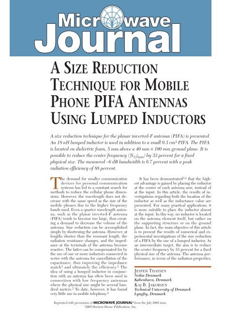
asize reduction technique for mobile phone pifa antennas ... - Speag
asize reduction technique for mobile phone pifa antennas ... - Speag
asize reduction technique for mobile phone pifa antennas ... - Speag

You also want an ePaper? Increase the reach of your titles
YUMPU automatically turns print PDFs into web optimized ePapers that Google loves.
A SIZE REDUCTION<br />
TECHNIQUE FOR MOBILE<br />
PHONE PIFA ANTENNAS<br />
USING LUMPED INDUCTORS<br />
A size <strong>reduction</strong> <strong>technique</strong> <strong>for</strong> the planar inverted-F antenna (PIFA) is presented.<br />
An 18 nH lumped inductor is used in addition to a small 0.3 cm 3 PIFA. The PIFA<br />
is located on dielectric foam, 5 mm above a 40 mm × 100 mm ground plane. It is<br />
possible to reduce the center frequency (|S 11 | min ) by 33 percent <strong>for</strong> a fixed<br />
physical size. The measured –6 dB bandwidth is 6.7 percent with a peak<br />
radiation efficiency of 88 percent.<br />
The demand <strong>for</strong> smaller communication<br />
devices <strong>for</strong> personal communication<br />
systems has led to a constant search <strong>for</strong><br />
methods to reduce the cellular <strong>phone</strong> dimensions.<br />
However, the wavelength does not decrease<br />
with the same speed as the size of the<br />
<strong>mobile</strong> <strong>phone</strong>s due to the higher frequency<br />
bands used. Even a quarter wavelength antenna,<br />
such as the planar inverted-F antenna<br />
(PIFA) tends to become too large, thus creating<br />
a demand to decrease the volume of the<br />
antenna. Size <strong>reduction</strong> can be accomplished<br />
simply by shortening the antenna. However, at<br />
lengths shorter than the resonant length, the<br />
radiation resistance changes, and the impedance<br />
at the terminals of the antenna become<br />
reactive. The latter can be compensated <strong>for</strong> by<br />
the use of one or more inductors connected in<br />
series with the antenna <strong>for</strong> cancellation of the<br />
capacitance, thus improving the impedance<br />
match 1 and ultimately the efficiency. 2 The<br />
idea of using a lumped inductor in conjunction<br />
with an antenna has often been used in<br />
connection with low frequency <strong>antennas</strong><br />
where the physical size might be several hundred<br />
meters. 3 To date, however, it has found<br />
very little use in <strong>mobile</strong> telephony. 4<br />
It has been demonstrated 3,4 that the highest<br />
advantage is gained by placing the inductor<br />
at the center of each antenna arm, instead of<br />
at the input. In this article, the results of investigations<br />
regarding both the location of the<br />
inductor as well as the inductance value are<br />
presented. For many practical applications, it<br />
is more suitable to place the inductor almost<br />
at the input. In this way, no inductor is located<br />
on the antenna element itself, but rather on<br />
the supporting structure or on the ground<br />
plane. In fact, the main objective of this article<br />
is to present the results of numerical and experimental<br />
investigations of the size <strong>reduction</strong><br />
of a PIFA by the use of a lumped inductor. As<br />
an intermediate target, the aim is to reduce<br />
the center frequency by 33 percent <strong>for</strong> a fixed<br />
physical size of the antenna. The antenna per<strong>for</strong>mance,<br />
in terms of the radiation properties,<br />
JESPER THAYSEN<br />
Nokia Denmark<br />
København, Denmark<br />
KAJ B. JAKOBSEN<br />
Technical University of Denmark<br />
Lyngby, Denmark<br />
Reprinted with permission of MICROWAVE JOURNAL ® from the July 2005 issue.<br />
© 2005 Horizon House Publications, Inc.
(a)<br />
REFLECTION COEFFICIENT (dB)<br />
0<br />
−6<br />
−12<br />
−18<br />
1.5 1.6 1.7 1.8<br />
0<br />
1.9<br />
(a)<br />
FREQUENCY (GHz)<br />
REFLECTION COEFFICIENT (dB)<br />
H<br />
W<br />
Short<br />
0<br />
−6<br />
−12<br />
0mm<br />
θ =<br />
“cut”<br />
Feed Point<br />
Ground<br />
φ = 0°<br />
90°<br />
φ = 0°<br />
θ = 90°<br />
φ = 0°<br />
(b)<br />
▲ Fig. 1 Schematic of the PIFA located<br />
above a ground plane (a), and antenna<br />
orientation in spherical coordinates (b).<br />
Measured Simulated<br />
−18<br />
1.0 1.1 1.2<br />
0<br />
1.3<br />
(b)<br />
FREQUENCY (GHz)<br />
+<br />
33mm from<br />
feed point<br />
100<br />
67<br />
33<br />
100<br />
67<br />
33<br />
EFFICIENCY (%)<br />
EFFICIENCY (%)<br />
▲ Fig. 2 Simulated and measured<br />
reflection coefficient and radiation efficiency<br />
<strong>for</strong> the unloaded 40 mm (a) and the unloaded<br />
60 mm (b) long PIFAs.<br />
scattering parameters, electrical nearfield<br />
distribution and current distribution,<br />
is simulated and verified by<br />
measurements. 5-8 The evaluation of<br />
the <strong>antennas</strong> in terms of the electrical<br />
field distribution and current distribution<br />
on the antenna element as well<br />
as on the ground plane has been accomplished<br />
using planar near-field<br />
L<br />
measurements. 9–12 The near-field is<br />
usually trans<strong>for</strong>med to far-field data.<br />
Nevertheless, it is the raw unprocessed<br />
near-field data that is presented<br />
and used in this article.<br />
MATERIALS AND METHODS<br />
The antenna configuration considered<br />
consists of a 40 mm long, 1.5<br />
mm wide and 5 mm high PIFA located<br />
on a 40 mm × 100 mm ground<br />
plane. In all the prototypes, Rohacell<br />
material (ε r = 1.06) is used as the supporting<br />
structure of the antenna. The<br />
antenna is located at the edge and<br />
parallel to the 100 mm edge, as illustrated<br />
in Figure 1. The feed point is<br />
located 5 mm from the edge where a<br />
90° bend <strong>for</strong>ms the short to the<br />
ground plane. In the cases where the<br />
inductor is incorporated on the antenna<br />
element, a 0.5 mm wide gap is<br />
cut in the antenna arm. In order to<br />
determine the optimal set-up with respect<br />
to the antenna per<strong>for</strong>mance,<br />
the location of the inductor is varied.<br />
Hence, the cut is moved from almost<br />
at the feed point, the 0.5 mm case,<br />
towards the open end, the 33 mm<br />
case.<br />
A planar scanner is used to per<strong>for</strong>m<br />
the measurements. 7 The step<br />
size is 4 mm leading to a total of 496<br />
measurement points <strong>for</strong> a 60 mm ×<br />
120 mm area. This area covers the<br />
ground plane plus an additional 10<br />
mm on each side of the ground<br />
plane. 9 A three-dimensional E-field<br />
probe is used <strong>for</strong> these measurements.<br />
The probe is designed <strong>for</strong><br />
electrical near-field component measurements<br />
up to 3 GHz. 8 The measurements<br />
are carried out at 1.06<br />
GHz, that is, the measured centre<br />
frequency (|S 11 | min ) of both the 40<br />
mm loaded as well as the 60 mm unloaded<br />
antenna. The measurement<br />
facility gives the total amplitude of<br />
the electrical fields. These measurements<br />
are compared to results obtained<br />
from the IE3D computer program<br />
used. 6<br />
In the planar scanning <strong>technique</strong><br />
the probe is moved in a plane situated<br />
in front of the antenna and the received<br />
signal (amplitude) is recorded.<br />
The position of the probe is characterised<br />
by the coordinates (x, y, z 0 ) in<br />
the xyz coordinate system of the antenna.<br />
During the scanning, z 0 is kept<br />
constant, while x and y is varied. The<br />
field is measured at a distance z 0 =<br />
TECHNICAL FEATURE<br />
3.2 mm, which corresponds to a free<br />
space distance of λ o /90, equivalent to<br />
an electrical length of 4°. It should be<br />
noted that the distance between the<br />
ground plane and the measurement<br />
plane is 8.2 mm (λ o /35), since the antenna<br />
height is 5 mm.<br />
THE UNLOADED PIFA<br />
In order to validate the per<strong>for</strong>mance<br />
of the loaded <strong>antennas</strong>, an unloaded<br />
prototype having the same dimension<br />
has been fabricated (L × W<br />
× H) = (40 mm × 1.5 mm × 5 mm).<br />
This antenna has a somewhat higher<br />
centre frequency compared to the<br />
loaded <strong>antennas</strong>. There<strong>for</strong>e, a larger<br />
unloaded antenna that has the same<br />
centre frequency (|S 11| min) as the<br />
loaded antenna is also presented (60<br />
mm × 1.5 mm × 5 mm). In this way, a<br />
more realistic comparison can be<br />
made.<br />
The simulated and measured reflection<br />
coefficient and radiation efficiency<br />
<strong>for</strong> two unloaded <strong>antennas</strong>, 40<br />
mm and 60 mm, are shown in Figure<br />
2. For the 60 mm PIFA the simulated<br />
centre frequency (|S 11 | min ) is 1.2<br />
GHz, 33 percent lower than the centre<br />
frequency (|S 11 | min ) <strong>for</strong> the 40 mm<br />
long PIFA, which is 1.8 GHz.<br />
For both <strong>antennas</strong>, the measured<br />
frequencies with the lowest reflection<br />
coefficient are approximately 10 percent<br />
lower than the simulated results.<br />
This difference could be caused by a<br />
slight difference in the simulated<br />
model and the prototype. The resolution<br />
used in the simulation can also<br />
cause some discrepancy. Here, converged<br />
results are obtained using 20<br />
cells per wavelength and edge cells. 6<br />
The measured total electrical field<br />
components of the radiation patterns<br />
<strong>for</strong> the 60 mm unloaded PIFA, shown<br />
in Figure 3, indicate good agreement<br />
between the simulated and the measured<br />
results. Note that the radiation<br />
patterns are obtained at the centre<br />
frequency (|S 11 | min ); there<strong>for</strong>e, the<br />
simulated patterns are at 1.23 GHz<br />
and the measured ones at 1.06 GHz.<br />
The measured maximum gain is 3.9<br />
dBi, slightly higher than the simulated<br />
gain.<br />
The total electrical near-field distribution<br />
at a distance of z 0 = 3.2 mm<br />
above the antenna element is shown in<br />
Figure 4. Good agreement in terms of<br />
peak amplitude and shape of the electrical<br />
near-field distribution between
Measured Simulated<br />
φ=180° 0°<br />
φ=0°<br />
5dB<br />
90°<br />
45°<br />
0<br />
−5<br />
−10<br />
−15<br />
45°<br />
90°<br />
(a)<br />
135°135°<br />
180°<br />
φ=180°<br />
0°<br />
φ=0°<br />
5dB<br />
45°<br />
45°<br />
0<br />
−5<br />
−10<br />
−15<br />
90°<br />
90°<br />
(b)<br />
270°<br />
(c)<br />
135°135°<br />
315°<br />
180°<br />
0°<br />
5dB<br />
0<br />
−5<br />
−10<br />
−15<br />
225°135°<br />
180°<br />
45°<br />
90°<br />
▲ Fig. 3 Total electrical field components<br />
of the radiation patterns <strong>for</strong> the 60 mm<br />
unloaded PIFA; (a) θ cuts <strong>for</strong> φ =0°, (b) <strong>for</strong><br />
φ =90° and (c) φ cut <strong>for</strong> φ =90°.<br />
the simulated and the measured results<br />
are obtained; however, more details<br />
could be observed from the simulated<br />
result. For instance, when observing<br />
just above the radiating<br />
element, especially at (x, y) = (0,<br />
40–70), a local minimum is found and<br />
the edge peak radiation is higher above<br />
the ground when compared to that obtained<br />
at the side of the ground plane.<br />
This is also in accordance with the<br />
measured radiation pattern shown previously.<br />
In both cases, the peak values<br />
are associated with the open end of the<br />
antenna, that is at (x, y) = (0, 40). Also,<br />
in both cases a minimum is observed at<br />
(x, y) = (40, 40), that is at the opposite<br />
edge of the PIFA.<br />
100<br />
80<br />
60<br />
40<br />
20<br />
0<br />
Total E field<br />
0 20 40<br />
60 mm, measured<br />
Either an inductor or a capacitor<br />
can be used to reduce the centre frequency<br />
(|S 11 | min ) from 1.8 GHz as <strong>for</strong><br />
the 40 mm long PIFA to 1.2 GHz.<br />
This frequency <strong>reduction</strong> corresponds<br />
to a size <strong>reduction</strong> of 33 percent,<br />
that is from 60 mm to 40 mm.<br />
INDUCTOR-LOADED PIFA<br />
Two different tests are made.<br />
First, <strong>for</strong> a fixed location of the inductor,<br />
the inductance is varied between<br />
5 and 100 nH. Hereafter, the<br />
optimal location is found <strong>for</strong> a fixed<br />
inductance value.<br />
Numerical Results<br />
Locating an inductor 10 mm from<br />
the feed point <strong>for</strong>ms the inductor<br />
loading. For this fixed location, the<br />
simulation results <strong>for</strong> varying the inductor<br />
value between 5 and 100 nH<br />
are shown in Figure 5. Here, the<br />
centre frequency (|S 11 | min ) and the<br />
bandwidth are plotted with respect to<br />
the 40 mm unloaded case. The centre<br />
frequency (|S 11 | min ) drops from 1.8<br />
GHz towards 0.87 GHz <strong>for</strong> inductor<br />
values above 70 nH. For values above<br />
35 nH, however, the bandwidth is<br />
lower than <strong>for</strong> the unloaded PIFA.<br />
This motivates the choice of an inductor<br />
value below 35 nH. Using 5<br />
nH, the bandwidth is 2.3 times the<br />
bandwidth <strong>for</strong> the unloaded PIFA,<br />
which is due to the improved impedance<br />
match. Between 5 and 35 nH,<br />
the optimal inductor value is a tradeoff<br />
between the decrease in centre<br />
frequency (|S 11 | min ) and the actual<br />
(v/m), (dB) Total E field (v/m), (dB)<br />
50<br />
50<br />
45<br />
40<br />
35<br />
30<br />
25<br />
100<br />
80<br />
60<br />
40<br />
20<br />
0<br />
0 20 40<br />
60 mm, simulated<br />
▲ Fig. 4 Measured and simulated total electrical near-field<br />
distribution <strong>for</strong> the 60 mm long unloaded PIFA at 1.06 GHz.<br />
TECHNICAL FEATURE<br />
45<br />
40<br />
35<br />
30<br />
25<br />
bandwidth. As a<br />
compromise, 20 nH<br />
is chosen <strong>for</strong> the<br />
rest of the work.<br />
Here, the centre<br />
frequency (|S 11 | min )<br />
is lowered by 30<br />
percent and the<br />
bandwidth is almost<br />
twice the bandwidth<br />
obtained <strong>for</strong><br />
the unloaded 40<br />
mm case.<br />
For a fixed inductance<br />
of 20 nH,<br />
various locations of<br />
the inductor have<br />
been simulated,<br />
spanning from almost<br />
at the feed<br />
point (0.5 mm) toward<br />
the open end<br />
(33 mm). The simulated centre frequency<br />
(|S 11 | min ) and relative bandwidth<br />
as a function of the location of<br />
the inductor, that is the distance from<br />
the feed point to the inductor, are<br />
shown in Figure 6. The lowest reflection<br />
coefficient and the peak efficiency<br />
as a function of the inductor<br />
location are shown in Figure 7.<br />
fo/fo unloaded<br />
1.0<br />
0.8<br />
0.6<br />
0.4<br />
0 25 50 75<br />
0<br />
100<br />
INDUCTOR VALUE (nH)<br />
3<br />
2<br />
1<br />
BW/BWunloaded<br />
▲ Fig. 5 Center frequency and bandwidth<br />
as a function of inductance <strong>for</strong> a fixed<br />
location (10 mm) on the PIFA.<br />
CENTER FREQUENCY (GHz)<br />
2.0<br />
1.8<br />
1.6<br />
1.4<br />
1.2<br />
1.0<br />
0<br />
0 5 10 15 20 25 30 35<br />
DISTANCE FROM THE FEED<br />
POINT TO THE INDUCTOR (mm)<br />
15<br />
12<br />
▲ Fig. 6 Simulated center frequency and<br />
bandwidth versus the inductor location.<br />
9<br />
6<br />
3<br />
RELATIVE BANDWIDTH (%)
REFLECTION COEFFICIENT (dB)<br />
0<br />
−10<br />
−20<br />
100<br />
67<br />
33<br />
RADIATION EFFICIENCY (%)<br />
−30<br />
0<br />
0 5 10 15 20 25 30 35<br />
DISTANCE FROM THE FEED<br />
POINT TO THE INDUCTOR (mm)<br />
▲ Fig. 7 Simulated reflection coefficient<br />
and radiation efficiency versus the inductor<br />
location.<br />
The centre frequency (|S 11 | min ) increases<br />
almost linearly from 1.2 to 1.8<br />
GHz, when the inductor is moved towards<br />
the open end, from a position at<br />
0.5 mm to 33 mm from the feed point.<br />
Starting with a 45 MHz or 4 percent<br />
bandwidth at 1.2 GHz (0.5 mm) the<br />
bandwidth drops due to mismatch, <strong>for</strong><br />
locations in the range from 5 to 20<br />
mm; hence, no –6 dB bandwidth occurs.<br />
The maximum bandwidth of 14.5<br />
percent is obtained at 26 mm, and stabilizes<br />
around 10 percent when the inductor<br />
is located at positions near the<br />
open end of the antenna (30 mm to 33<br />
mm).<br />
The peak efficiency starts at 75<br />
percent and ends at 60 percent, close<br />
to the feed point (0.5 mm) and the<br />
open end (33 mm), respectively. At<br />
locations below 5 mm, the efficiency<br />
is higher than 75 percent. Above 5<br />
mm, a decrease in the efficiency is<br />
observed, and the efficiency is below<br />
50 percent from 10 to 30 mm. Above<br />
31 mm, the reflection coefficient is<br />
–11 dB and the efficiency exceeds 50<br />
percent, and reaches a peak of 60<br />
percent at 33 mm. In between, the<br />
efficiency has dropped to 17 percent<br />
at the 21 mm location.<br />
The lowest reflection coefficient<br />
changes from –9 to –1.5 dB when the<br />
distance from the feed point to the inductor<br />
increases from 0.5 to 20 mm.<br />
From 21 to 26 mm the reflection coefficient<br />
peaks at –30 dB, ending at<br />
–11 dB <strong>for</strong> locations above 30 mm.<br />
Experimental Results<br />
Based on the results from the parameter<br />
study, a prototype 40 mm<br />
long PIFA, loaded with an inductor,<br />
has been measured with respect to<br />
radiation efficiency and reflection coefficient.<br />
A lumped 18 nH inductor is<br />
used in the experiments. 13 The in-<br />
REFLECTION COEFFICIENT (dB)<br />
0<br />
−6<br />
−12<br />
−18<br />
1.00 1.05 1.10<br />
0<br />
1.15<br />
FREQUENCY (GHz)<br />
100<br />
67<br />
33<br />
▲ Fig. 8 Comparison of the measured<br />
reflection coefficient and efficiency of a 60<br />
mm long, unloaded PIFA (dashed line) and<br />
40 mm long PIFA loaded with an inductor<br />
(solid line).<br />
RADIATION EFFICIENCY (%)<br />
ductor has an inductance of nearly 20<br />
nH in the frequency range of interest.<br />
The results, compared to the unloaded<br />
60 mm long PIFA, are shown<br />
in Figure 8.<br />
For the PIFA without any inductor,<br />
the centre frequency (|S 11 | min ) is<br />
1.06 GHz with a peak return loss of<br />
16.5 dB. The bandwidth is 7.3 percent<br />
(78 MHz). The measured efficiency<br />
is greater than 65 percent<br />
within this frequency range of interest,<br />
where the peak efficiency is 85<br />
percent. By loading this antenna with<br />
an 18 nH inductor soldered at the<br />
gap, just 0.5 mm from the feed point,<br />
the centre frequency (|S 11 | min ) is 1.07<br />
GHz, with a bandwidth of 6.7 percent<br />
(71 MHz). The peak efficiency is<br />
88 percent.<br />
The total electrical field components<br />
of the radiation patterns, shown<br />
in Figure 9, indicate almost omni-directional<br />
properties <strong>for</strong> the 40 mm long<br />
inductor-loaded PIFA. There is good<br />
agreement between the simulation and<br />
measurement results. The measured<br />
maximum gain is 3.3 dBi, slightly higher<br />
than the simulated gain.<br />
In Figure 10, the measured total<br />
electrical field distribution of the 40<br />
mm long, 18 nH inductor-loaded<br />
PIFA is compared with the one of the<br />
60 mm long, unloaded PIFA. It indicates<br />
a higher amplitude above the<br />
inductor-loaded antenna, compared<br />
to the 60 mm one. This originates<br />
from the higher current distribution<br />
that is inevitably present, and thus<br />
higher radiation from this area.<br />
In the lower half of the pictures,<br />
the electrical field distribution behaves<br />
identically, with slightly higher<br />
values <strong>for</strong> the 60 mm case. Also, the<br />
null that appears at the opposite side<br />
TECHNICAL FEATURE<br />
Measured Simulated<br />
φ=180° 0°<br />
φ=0°<br />
5dB<br />
45°<br />
0<br />
−5<br />
45°<br />
(a)<br />
90°<br />
135°135°<br />
180°<br />
135°135°<br />
180°<br />
90°<br />
φ=180°<br />
0°<br />
φ=0°<br />
5dB<br />
45°<br />
45°<br />
0<br />
−5<br />
(b)<br />
90°<br />
270°<br />
315°<br />
−10<br />
−15<br />
−10<br />
−15<br />
0°<br />
5dB<br />
0<br />
−5<br />
−10<br />
−15<br />
45°<br />
225°135°<br />
90°<br />
90°<br />
180°<br />
(c)<br />
▲ Fig. 9 Simulated and measured total<br />
electrical field components of the radiation<br />
pattern; (a) θ cuts <strong>for</strong> φ =0°, (b) θ cuts <strong>for</strong><br />
φ =90° and (c) φ cuts <strong>for</strong> φ =90°.<br />
(x, y) = (40, 50) of the PIFA in the 60<br />
mm case could be found in the 40<br />
mm case.<br />
The PIFA is basically an inverted-L<br />
antenna that actually comes from a<br />
monopole with a bend such that most<br />
of the arm is parallel to the ground<br />
plane. This means that the feed point is<br />
moved by a certain distance from the<br />
ground, here 5 mm from the bend and<br />
an additional 5 mm due to the antenna<br />
height; hence, the optimum location of<br />
the inductor is between 10.5 mm and<br />
15 mm from the ground connection,<br />
that is almost one-third the total length<br />
of 45 mm (length plus height). Collin 4<br />
argues that the optimum location of an<br />
inductor is at the centre of the arm of
100<br />
80<br />
60<br />
40<br />
20<br />
0<br />
Total E field (v/m), (dB) Total E field (v/m), (dB)<br />
60<br />
60<br />
55<br />
50<br />
45<br />
40<br />
35<br />
30<br />
0 20 40 0 20 40<br />
60 mm, unloaded 40 mm, unloaded<br />
▲ Fig. 10 Measured current distribution<br />
<strong>for</strong> the inductor loaded versus unloaded.<br />
the monopole; of course, that cannot<br />
be compared directly to the PIFA.<br />
Nevertheless, this actually holds <strong>for</strong> the<br />
impedance match. If the inductor is located<br />
between 21 and 26 mm, a rather<br />
good simulated impedance match below<br />
–25 dB is observed. In this case the<br />
decrease in the frequency, with the<br />
lowest reflection coefficient, is not<br />
overwhelming, a <strong>reduction</strong> from only<br />
1.8 to 1.7 GHz. Moreover, the radiation<br />
efficiency is below 25 percent. This<br />
could indicate that the optimum location<br />
<strong>for</strong> an inductor in the PIFA is closer<br />
to the feed point.<br />
Above 21 mm no significant frequency<br />
<strong>reduction</strong> is obtained. At 30<br />
mm, however, the bandwidth is 200<br />
MHz (13 percent), which is higher<br />
than the case of no inductor (50 MHz<br />
or 3 percent). Thus, the higher bandwidth<br />
is at the expense of an inductor<br />
in terms of reduced efficiency and<br />
the cost of the inductor.<br />
CONCLUSION<br />
A small 0.3 cm 3 PIFA, located on dielectric<br />
foam 5 mm above a 40 mm ×<br />
100 mm ground plane, is investigated.<br />
Adding an inductor on the arm of the<br />
PIFA improves the per<strong>for</strong>mances <strong>for</strong><br />
the shown PIFA. The best case with respect<br />
to centre frequency (|S 11 | min ) <strong>reduction</strong><br />
is obtained when an 18 nH<br />
lumped inductor is placed within the<br />
100<br />
80<br />
60<br />
40<br />
20<br />
0<br />
55<br />
50<br />
45<br />
40<br />
35<br />
30<br />
first few millimetres from the feed<br />
point. Here, the measured frequency<br />
point with the lowest reflection coefficient<br />
is decreased by 33 percent, from<br />
1.60 to 1.06 GHz, the reflection coefficient<br />
is –16.5 dB, the measured –6 dB<br />
bandwidth is 6.7 percent and the radiation<br />
peak efficiency is 88 percent.<br />
When comparing the 40 mm inductor-loaded<br />
antenna with the 60<br />
mm unloaded antenna, the major<br />
benefit includes the reduced size <strong>for</strong><br />
a fixed centre frequency (|S 11 | min ).<br />
This, however, comes at the expense<br />
of reduced efficiency and bandwidth.<br />
By the use of inductor loading, it is<br />
shown that <strong>for</strong> a fixed size the centre<br />
frequency (|S 11 | min ) can be decreased.<br />
The principle could also be used <strong>for</strong> a<br />
fixed frequency, where a 30 to 40<br />
percent size <strong>reduction</strong> is expected.<br />
The PIFAs shown are not fully optimized<br />
with respect to the occupied<br />
volume or frequency, nor is any other<br />
component or cover included. Thus,<br />
<strong>for</strong> practical use, both the shape of<br />
the antenna and the shape of the distributed<br />
inductor should be carefully<br />
chosen in order to get the best frequency<br />
bandwidth and efficiency per<strong>for</strong>mance<br />
<strong>for</strong> a given application. ■<br />
ACKNOWLEDGMENT<br />
This work has been supported by<br />
Nokia Denmark.<br />
References<br />
1. C.W. Harrington, “Monopole with Inductive<br />
Loading,” IEEE Transactions on Antennas<br />
and Propagation, July 1963,<br />
pp. 394–400.<br />
2. G.S. Smith, “Efficiency of Electrically<br />
Small Antennas Combined with Matching<br />
Networks,” IEEE Transactions on Antennas<br />
and Propagation, Vol. 25, May 1977,<br />
pp. 369–373.<br />
3. G. Hall (Ed.), The ARRL Antenna Book,<br />
15 th Edition, Chapter 7, “The American<br />
Radio Relay League,” Newington, CT,<br />
1990.<br />
4. R.E. Collin, Antennas and Radiowave<br />
Propagation, McGraw-Hill, New York, NY,<br />
1985, pp. 97–104.<br />
TECHNICAL FEATURE<br />
5. www.satimo.com.<br />
6. www.zeland.com.<br />
7. www.semcad.com.<br />
8. www.speag.com.<br />
9. A.W. Rudge (Ed.), The Handbook of Antenna<br />
Design, Chapter 8, “Antenna Measurements,”<br />
Peter Pelegrinus Ltd., 1982.<br />
10. R.C. Baird, A.C. Newell and C.F. Stubenrauch,<br />
“A Brief History of Near-field Measurements<br />
of Antennas at the National Bureau<br />
of Standards,” IEEE Transactions on<br />
Antennas and Propagation, Vol. 36, No. 6,<br />
1988.<br />
11. Y. Gao and I. Wolff, “A New Miniature<br />
Magnetic Field Probe <strong>for</strong> Measuring<br />
Three-dimensional Fields in Planar High<br />
Frequency Circuits,” IEEE Transactions<br />
on Microwave Theory and Techniques, Vol.<br />
44, No. 6, June 1996, pp. 911–918.<br />
12. Y. Gao and I. Wolff, “Miniature Electric<br />
Near-field Probe <strong>for</strong> Measuring 3-D Fields<br />
in Planar Microwave Circuits,” IEEE<br />
Transactions on Microwave Theory and<br />
Techniques, Vol. 46, No. 7, July 1998,<br />
pp. 907–913.<br />
13. www.coilcraft.com.<br />
Jesper Thaysen<br />
received his MSc<br />
degree from the<br />
Technical University of<br />
Denmark, Kgs.<br />
Lyngby, Denmark, in<br />
2000. He is currently<br />
working toward his<br />
PhD degree. He has<br />
been with Nokia<br />
Denmark since 2001.<br />
His current interests<br />
include broadband <strong>antennas</strong>, small <strong>antennas</strong><br />
and multi-elements <strong>antennas</strong>.<br />
Kaj B. Jakobsen<br />
received his MScEE<br />
degree from the<br />
Technical University of<br />
Denmark, Kgs.<br />
Lyngby, Denmark, in<br />
1986, his PhD degree<br />
from the University of<br />
Dayton, OH, in 1989,<br />
and his graduate<br />
diploma in business<br />
administration,<br />
organization and management from<br />
Copenhagen Business School, Denmark, in<br />
2000. His research interests include GPR,<br />
<strong>antennas</strong>, microwaves, electromagnetics and<br />
related interdisciplinary topics. Since 1990, he<br />
has been a professor at the Technical<br />
University of Denmark, from where he<br />
received the “Teacher of the Year” award in<br />
1994.