DIY Kit 89. STEREO VU METER - Ozitronics
DIY Kit 89. STEREO VU METER - Ozitronics
DIY Kit 89. STEREO VU METER - Ozitronics

You also want an ePaper? Increase the reach of your titles
YUMPU automatically turns print PDFs into web optimized ePapers that Google loves.
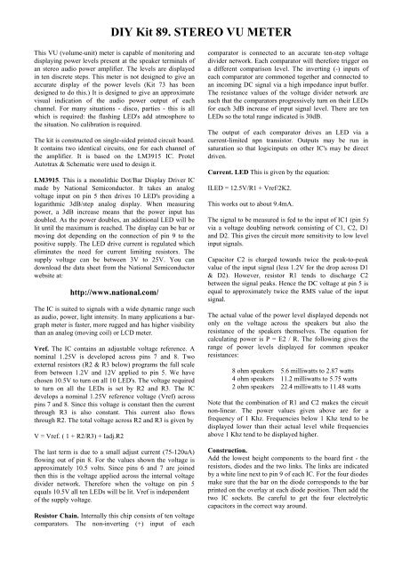
<strong>DIY</strong> <strong>Kit</strong> <strong>89.</strong> <strong>STEREO</strong> <strong>VU</strong> <strong>METER</strong>This <strong>VU</strong> (volume-unit) meter is capable of monitoring anddisplaying power levels present at the speaker terminals ofan stereo audio power amplifier. The levels are displayedin ten discrete steps. This meter is not designed to give anaccurate display of the power levels (<strong>Kit</strong> 73 has beendesigned to do this.) It is designed to give an approximatevisual indication of the audio power output of eachchannel. For many situations - disco, parties - this is allwhich is required: the flashing LED's add atmosphere tothe situation. No calibration is required.The kit is constructed on single-sided printed circuit board.It contains two identical circuits, one for each channel ofthe amplifier. It is based on the LM3915 IC. ProtelAutotrax & Schematic were used to design it.LM3915. This is a monolithic Dot/Bar Display Driver ICmade by National Semiconductor. It takes an analogvoltage input on pin 5 then drives 10 LED's providing alogarithmic 3dB/step analog display. When measuringpower, a 3dB increase means that the power input hasdoubled. As the power doubles, an additional LED will belit until the maximum is reached. The display can be bar ormoving dot depending on the connection of pin 9 to thepositive supply. The LED drive current is regulated whicheliminates the need for current limiting resistors. Thesupply voltage can be between 3V to 25V. You candownload the data sheet from the National Semiconductorwebsite at:http://www.national.com/The IC is suited to signals with a wide dynamic range suchas audio, power, light intensity. In many applications a bargraphmeter is faster, more rugged and has higher visibilitythan an analog (moving coil) or LCD meter.Vref. The IC contains an adjustable voltage reference. Anominal 1.25V is developed across pins 7 and 8. Twoexternal resistors (R2 & R3 below) programs the full scalefrom between 1.2V and 12V applied to pin 5. We havechosen 10.5V to turn on all 10 LED's. The voltage requiredto turn on all the LEDs is set by R2 and R3. The ICdevelops a nominal 1.25V reference voltage (Vref) acrosspins 7 and 8. Since this voltage is constant then the currentthrough R3 is also constant. This current also flowsthrough R2. The total voltage across R2 and R3 is given byV = Vref. ( 1 + R2/R3) + Iadj.R2The last term is due to a small adjust current (75-120uA)flowing out of pin 8. For the values shown the voltage isapproximately 10.5 volts. Since pins 6 and 7 are joinedthen this is the voltage applied across the internal voltagedivider network. Therefore when the voltage on pin 5equals 10.5V all ten LEDs will be lit. Vref is independentof the supply voltage.Resistor Chain. Internally this chip consists of ten voltagecomparators. The non-inverting (+) input of eachcomparator is connected to an accurate ten-step voltagedivider network. Each comparator will therefore trigger ona different comparison level. The inverting (-) inputs ofeach comparator are commoned together and connected toan incoming DC signal via a high impedance input buffer.The resistance values of the voltage divider network aresuch that the comparators progressively turn on their LEDsfor each 3dB increase of input signal level. There are tenLEDs so the total range indicated is 30dB.The output of each comparator drives an LED via acurrent-limited npn transistor. Outputs may be run insaturation so that logicinputs on other IC's may be directdriven.Current. LED This is given by the equation:ILED = 12.5V/R1 + Vref/2K2.This works out to about 9.4mA.The signal to be measured is fed to the input of IC1 (pin 5)via a voltage doubling network consisting of C1, C2, D1and D2. This gives the circuit more sensitivity to low levelinput signals.Capacitor C2 is charged towards twice the peak-to-peakvalue of the input signal (less 1.2V for the drop across D1& D2). However, resistor R1 tends to discharge C2between the signal peaks. Hence the DC voltage at pin 5 isequal to approximately twice the RMS value of the inputsignal.The actual value of the power level displayed depends notonly on the voltage across the speakers but also theresistance of the speakers themselves. The equation forcalculating power is P = E2 / R. The following gives therange of power levels displayed for common speakerresistances:8 ohm speakers 5.6 milliwatts to 2.87 watts4 ohm speakers 11.2 milliwatts to 5.75 watts2 ohm speakers 22.4 milliwatts to 11.48 wattsNote that the combination of R1 and C2 makes the circuitnon-linear. The power values given above are for afrequency of 1 Khz. Frequencies below 1 Khz tend to bedisplayed lower than their actual level while frequenciesabove 1 Khz tend to be displayed higher.Construction.Add the lowest height components to the board first - theresistors, diodes and the two links. The links are indicatedby a white line next to pin 9 of each IC. For the four diodesmake sure that the bar on the diode corresponds to the barprinted on the overlay at each diode position. Then add thetwo IC sockets. Be careful to get the four electrolyticcapacitors in the correct way around.
<strong>DIY</strong> <strong>Kit</strong> <strong>89.</strong> <strong>STEREO</strong> <strong>VU</strong> <strong>METER</strong>LED's. We have supplied 7 green & 3 red LED's per audiochannel.We suggest you use the three red LED's to indicatewhen the power is at its highest. This is at positions L8 L9& L10 for IC1, and L18 L19 & L20 for IC2. Before yousolder the LED's into place you must do three things: firstdecide how high you need to have the LED's above thePCB for the particular application or case you have inmind.Secondly, you must determine which lead of the LED is thecathode & which is the anode. The short lead of the LEDindicates the cathode. This is the lead which corresponds tothe bar on the LED symbol on the overlay.COMPONENTSResistors, 5%, 1/4W:18K brown grey orange R2 R5 22K7 red violet red R3 R6 210K brown black orange R1 R4 21uF 50V ecap C1 C2 C3 C4 4Green rectangular LED 14Red rectangular LED 6LM3915 IC1 IC2 218 pin IC socket 2K89 PCB 1Thirdly, & very important: you want the LED's to all bein a nice neat line, correct. Well soldering by hand will notgive this result. Use a piece of sticky tape to hold theLED's securely in place while you solder. This will alsohelp you get the desired height above the PCB. After theLED's are in place add the IC sockets & the IC's. Solderthe power and audio cables to the pads as indicated. After afinal check turn on the power and the audio input. If youhave an audio frequency generator set it up to deliver about6V on a sinewave of 1kHz. Eight or nine of the LED'sshould turn on. If this is not the case check that allcomponents are in their correct positions and with the rightorientation. Are the two links in the board? Are the IC'saround the correct way.Prescaling. Higher power levels can be displayed byadding a voltage divider network at the input to the meter.For example, a 2-to-1 voltage divider means that themaximum power able to be displayed would be increasedby four times. A 3-to-1 divider means an increase of 9times, etc. (See Reference 3 for a circuit to do this.)References:1. The full data sheets on the LM3915 can be found in theSpecialPurpose Linear Devices, data book from NationalSemiconductor,page 5-240. Better still download it fromtheir website as given above.2. Optoelectronics Circuits Manual by R. M. Marston,published by Newnes. Pages 52 - 65.3. Build This Audio Power Meter & Worry No More, byDarren Yates. Silicon Chip, April 1993, pages 22 - 25.
<strong>DIY</strong> <strong>Kit</strong> <strong>89.</strong> <strong>STEREO</strong> <strong>VU</strong> <strong>METER</strong>