Electrical specifications - Seli GmbH
Electrical specifications - Seli GmbH
Electrical specifications - Seli GmbH

You also want an ePaper? Increase the reach of your titles
YUMPU automatically turns print PDFs into web optimized ePapers that Google loves.
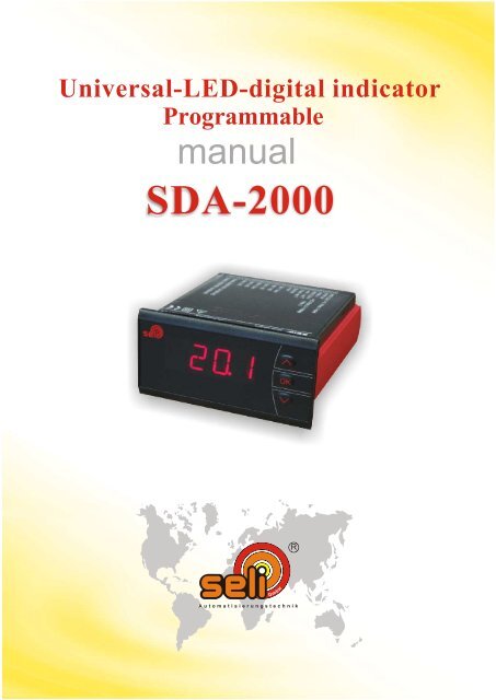
Universal-LED-digital indicator<br />
Programmable<br />
manual<br />
SDA-2000<br />
HH<br />
bb<br />
mm<br />
GG<br />
R<br />
Automatisierungstechnik
Table of Contents<br />
Warnings ............................................................................. 2<br />
Safety instructions.............................................................. 3<br />
Front- and back layout ........... ........................................... 4<br />
Applications........................................................................ 5<br />
Technical characteristics.................................................... 5<br />
Mounting ............................................................................ 5<br />
Applications........................................................................ 6<br />
Order Codes ....................................................................... 7<br />
<strong>Electrical</strong> <strong>specifications</strong>...................................................... 7<br />
Sensor error <strong>specifications</strong> ................................................ 8<br />
Connections ....................................................................... 12<br />
Block diagram .................................................................. 13<br />
Routing diagram................................................................. 14<br />
Scrolling help text .............................................................. 16<br />
Configuration / operating the function keys ...... ................ 18<br />
Graphic depiction of the relay function setpoint ................ 19<br />
From ser.no. 060137001<br />
1
GENERAL<br />
HAZARD-<br />
OUS<br />
VOLTAGE<br />
WARNING<br />
This module is designed for connection to hazardous electric<br />
voltages. Ignoring this warning can result in severe personal<br />
injury or mechanical damage. To avoid the risk of electric shock<br />
and fire, the safety instructions of this manual must be observed<br />
and the guidelines followed. The <strong>specifications</strong> must not be<br />
exceeded, and the module must only be applied as described<br />
in the following. Prior to the commisioning of the module, this<br />
manual must be examined carefully. Only qualified personnel<br />
(technicians) should install this module.<br />
If the epuipment is used in a manner not specified by the<br />
manufactorer, the protection provided by the epuipment may<br />
be impaired.<br />
WARNING<br />
Until the module is fixed, do not connect hazardous voltages to<br />
the module.<br />
The following operations should only be carried out on a<br />
disconnected module and under ESD safe conditions:<br />
Troubleshooting the module.<br />
Repair of the module and change of fuses must be done by<br />
seli <strong>GmbH</strong> Automatisierungstechnik only<br />
Zeichenerklärungen<br />
Triangle with an exclamation mark: Warning / demand. Potentially<br />
lethal situations.<br />
The CE mark proves the compliance of the module with the essential<br />
requirements of the directives.<br />
2
DEFINITIONS:<br />
ENVIROMENT:<br />
MOUNTING:<br />
SAFETY INSTRUCTIONS<br />
Hazardous voltages have been defined as the ranges: 75 to 1500 Vot DC, and<br />
50 to 1000 Volt AC.<br />
Technicians are qualified persons educated or trained to mount, operate, and<br />
also troubleshoot technically correct and in accordance with safety regulations.<br />
Operators, being familiar with the contents of this manual, adjust and operate<br />
the knobs or potentiometers during normal operation.<br />
RECEIPT AND UNPACKING:<br />
Unpack the module without damaging it and make sure that the manual always<br />
follows the module and is always available. The packing should always follow<br />
the module until this has been permanently mounted.<br />
Check at the receipt of the module whether the type corresponds to the one<br />
ordered.<br />
Avoid direct sunlight, dust, high temperatures, mechanical vibrations and shock,<br />
as well as rain and heavy moisture. If necessary, heating in excess of the stated<br />
limits for ambient temperatures should be avoided by way of ventilation.<br />
All modules fall under Installation Category II, Pollution Degree 1, and Insulation<br />
Class II<br />
Only technicians who are familiar with the technical terms, warnings, and<br />
instructions in the manual and who are able to follow these should connect the<br />
module<br />
Should there be any doubt as to the correct handling of the module, pleas contact<br />
<strong>Seli</strong> Automatisierungstechnik <strong>GmbH</strong>, Dieselstr. 13<br />
48485 Neuenkirchen, Tel. (0 59 73) 94 74-0.<br />
Mounting and connection of the module should comply with national legislation<br />
for mounting of electric materials, i.a. wire cross section, protective fuse, and<br />
location. Descriptions of Input / Output and supply connections are shown in<br />
the block diagram and side label.<br />
3
Front- and BACK LAYOUT<br />
Picture 1: Front of the SDA-2000<br />
Picture 2: Back of the SDA-2000<br />
4
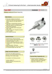
Programmable LED Indicator<br />
SDA-2000<br />
4-digit 14-segment LED indicator<br />
Input for mA, V, RTD, TC und potentiometer<br />
2 relay and analogue output<br />
Universal voltage supply<br />
Front key programmable<br />
Application:<br />
Display for digital readout of current, voltage, temperature of pot. Signals<br />
Process control with 2 pairs of potential-free relays and / or analogue output<br />
For local readout in extremely wet atmospheres with a specially designed<br />
splash-proof cover.<br />
Technical characteristics:<br />
4-digit LED indicator with 13.8 mm 14-segment characters. Max. Display readout<br />
-1999...9999 with programmable decimal point, relay ON / OFF indicatrion.<br />
All operational parameters can be adjusted to any application by use of the<br />
front keys.<br />
SDA is available fully-configured acc. To <strong>specifications</strong> ready for process<br />
control and visualisation.<br />
Help texts in eight languages can be selected via a menu item.<br />
In versions with relay outputs the user can minimise the installation test time<br />
by activating / deactivating each relay independently of the input signal.<br />
Mounting<br />
To be mounted in front panel. The includes rubber packing must be mounted<br />
between the panel cutout hole and the display front to obtain Ip65 (NEMA 4)<br />
tightness. For extra protection in extreme enviroments, SDA can be<br />
delivered with a specially designed splash-proof cover as accessory.<br />
5
* (e.g. Pt100, Ni100...)<br />
*<br />
6
Type<br />
SDA-2000 No<br />
: A<br />
Yes<br />
: B<br />
NB: Please order the splash-proof cover sperately.<br />
<strong>Electrical</strong> <strong>specifications</strong>:<br />
Specifications range:<br />
-20°C bis +60°C<br />
Common <strong>specifications</strong><br />
Supply voltage, universal .................. 21,6...253 VAC, 50...60Hz or<br />
19,2...300 VDC<br />
Max. Consumption ..................................... < 3,5 W<br />
Isolation voltage, test / operation.............. 2,3 kVAC / 250 VAC<br />
Signal- / noise ratio. ......................... min. 60 dB (0...100 kHz)<br />
Response time (0...90%, 100...10%) programmable<br />
Temperature input ...............................1...60s<br />
mA- / V- / mV-input .......................... 0,4...60 s<br />
Calibration temperature ............................. 20...28°C<br />
Accuracy, the greater of general and basic values:<br />
Input type<br />
Order Code:<br />
General values<br />
SDA-2000- -<br />
2 Relays Analogue output<br />
No<br />
Yes<br />
Absolute Temperatureaccuracy<br />
Coefficient<br />
: A<br />
: B<br />
All < ±0,1% of reading < ±0,01% of reading. / °C<br />
7
�<br />
��<br />
�<br />
�<br />
8
SDA-2000-A-A<br />
SDA-2000-B-A<br />
SDA-2000-A-B<br />
SDA-2000-B-B<br />
SDA<br />
10
CONNECTIONS<br />
Supply:<br />
Inputs:<br />
RTD, 2-wire RTD, 3-wire RTD, 4-wire<br />
TC 2-wire transmitter Current<br />
Voltage Potentiometer<br />
Output<br />
Current Relays<br />
12
Supply<br />
2-wire supply<br />
> 15 VDC<br />
Supply<br />
Input<br />
BLOCK DIAGRAM<br />
Output<br />
Common<br />
Relay 1 N.O.<br />
RTD,<br />
wires<br />
Relay 1 N.C.<br />
Common<br />
Relay 2 N.O.<br />
Relay 2 N.C.<br />
SDA-2000<br />
Input gnd.<br />
13
Hold<br />
Routing Diagram<br />
If no keys are activated for 2 minutes the display returns to default state<br />
1.0 without saving configuration changes .<br />
Increase value / choose next parameter<br />
Decrease value / choose previous parameter<br />
Save the chosen parameter and go to next menu<br />
Back to previous menu / return to menu 1.0 without saving<br />
15
SCROLLING HELP TEXT<br />
16
Documentation for routing diagram.<br />
In general<br />
When configuring the display you are guided through all parameters, you can<br />
choose the settings which fit the application. For each menu there is a scrolling<br />
help text which is automatically shown in the display, this starts after 5<br />
seconds if no key has been activated.<br />
OK<br />
Configuration / Operating The<br />
Funktion Keys<br />
Configuration is carried out by using the 3 function keys.<br />
will increase the numerical value or choose the next parameter<br />
will decrease the numerical value or choose the previous parameter<br />
will accept the cosen value and end the menu.<br />
If a funktion does not exist in the display all parameters are skipped to make<br />
the configuration as simple as possible.<br />
Once the configuration has been entered the display will show “---”.<br />
Pressing and holding OK will return to the previous menu or return to the default<br />
state (1.0) without saving the changed values or parameters.<br />
If no key is activated for 2 minutes, the display will return to the default state<br />
(1.0) without saving the changed values or parameters.<br />
Further explanations:<br />
Fast setpoint adjustment and relay test: These menus allow you to change<br />
the set point quickly and to check the operation ot the relays.<br />
Pressing and at the same time will change the state of the relay - this change<br />
is indicated by the diodes on the display. Pressing OK will save the set point change.<br />
Holding down OK for mor than0.5 seconds will return the unit to the default state<br />
without changing the set point.<br />
Password protection:<br />
Using a password will stop acces to the menu and parameters. There are two<br />
levels of password protection. Passwords between 0000...4999 allow access<br />
to the fast set point adjustment and relay test. (Using this password stops<br />
access to all other parts of the menu). Passwords between 5000...9999 stop<br />
access to all parts of the menu, fast set point and relay test. (Current set<br />
point is still shown). By using the master password 2008, all configuration<br />
menus are available<br />
18
Graphic depiction of the relay function setpoint:<br />
Relay units<br />
Relay action: increasing<br />
Setpoint = 50<br />
Hysteresis = 10<br />
Relay units<br />
Relay action: decreasing<br />
Hysteresis = 10<br />
Setpoint = 50<br />
19