SEEBURG HDLM8 Operation Manual - Seeburg acoustic line
SEEBURG HDLM8 Operation Manual - Seeburg acoustic line
SEEBURG HDLM8 Operation Manual - Seeburg acoustic line

Create successful ePaper yourself
Turn your PDF publications into a flip-book with our unique Google optimized e-Paper software.
<strong>SEEBURG</strong> <strong>HDLM8</strong><br />
<strong>Operation</strong> <strong>Manual</strong><br />
HIGH DEFINITION LOUDSPEAKER MANAGEMENT
Some functions described in this manual are tagged with the following symbol:<br />
FULL<br />
VERSION<br />
These functions are only available in the full version of the <strong>HDLM8</strong>. Ask your dealer for an upgrade.<br />
The manual is related to the <strong>HDLM8</strong> firmware version 1.2.0<br />
2010-2011, Revision H<br />
Copyright<br />
<strong>SEEBURG</strong> <strong>acoustic</strong> <strong>line</strong> GmbH<br />
Auweg 32<br />
D-89250 Senden<br />
GERMANY<br />
www.seeburg.net<br />
WEEE-Reg.-Nr.: DE 29853309<br />
You may download this manual directly from your <strong>HDLM8</strong> by following URL:<br />
http:///manual.pdf<br />
Do not open the top cover of the <strong>HDLM8</strong>. There are no user serviceable parts<br />
inside. Improper operation, handling or maintenance can result in death or severe<br />
injury.
Contents<br />
1 Introduction 7<br />
1.1 Signal Path . . . . . . . . . . . . . . . . . . . . . . . . . . . . . . . . . . . . . . . . . . . . 7<br />
1.2 Installation and Heat Dissipation . . . . . . . . . . . . . . . . . . . . . . . . . . . . . . . . 8<br />
1.3 Restoring after Power Failure . . . . . . . . . . . . . . . . . . . . . . . . . . . . . . . . . . 8<br />
1.4 dBu, dBV, dBFS and dBGR . . . . . . . . . . . . . . . . . . . . . . . . . . . . . . . . . . 9<br />
1.4.1 dBu vs. dBFS . . . . . . . . . . . . . . . . . . . . . . . . . . . . . . . . . . . . . . 9<br />
1.4.2 dBV . . . . . . . . . . . . . . . . . . . . . . . . . . . . . . . . . . . . . . . . . . . . 9<br />
1.4.3 dBGR . . . . . . . . . . . . . . . . . . . . . . . . . . . . . . . . . . . . . . . . . . . 9<br />
1.5 Definition of Terms . . . . . . . . . . . . . . . . . . . . . . . . . . . . . . . . . . . . . . . . 9<br />
1.5.1 Project . . . . . . . . . . . . . . . . . . . . . . . . . . . . . . . . . . . . . . . . . . 9<br />
1.5.2 Loudspeaker . . . . . . . . . . . . . . . . . . . . . . . . . . . . . . . . . . . . . . . 10<br />
1.5.3 Loudspeaker Editor . . . . . . . . . . . . . . . . . . . . . . . . . . . . . . . . . . . 10<br />
1.5.4 Input Bus . . . . . . . . . . . . . . . . . . . . . . . . . . . . . . . . . . . . . . . . . 10<br />
1.5.5 Output . . . . . . . . . . . . . . . . . . . . . . . . . . . . . . . . . . . . . . . . . . 10<br />
1.6 FAQ – Frequently Asked Questions . . . . . . . . . . . . . . . . . . . . . . . . . . . . . . . 10<br />
1.6.1 Why is there no Low Pass Filter (LPF)? . . . . . . . . . . . . . . . . . . . . . . . . 10<br />
1.6.2 Why can’t I set a particular Tweeter Louder? . . . . . . . . . . . . . . . . . . . . . 10<br />
2 Connections 11<br />
2.1 Power Supply . . . . . . . . . . . . . . . . . . . . . . . . . . . . . . . . . . . . . . . . . . . 11<br />
2.2 Analog Inputs and Outputs . . . . . . . . . . . . . . . . . . . . . . . . . . . . . . . . . . . 11<br />
2.2.1 Unbalanced Devices . . . . . . . . . . . . . . . . . . . . . . . . . . . . . . . . . . . 11<br />
2.2.2 Auto Muting on Power Failure . . . . . . . . . . . . . . . . . . . . . . . . . . . . . 11<br />
2.3 AES/EBU Digital Input . . . . . . . . . . . . . . . . . . . . . . . . . . . . . . . . . . . . . 11<br />
2.4 Optional ADAT Optical Interface . . . . . . . . . . . . . . . . . . . . . . . . . . . . . . . . 12<br />
2.5 <strong>SEEBURG</strong> Remote Interface (EIA-485) . . . . . . . . . . . . . . . . . . . . . . . . . . . . 12<br />
2.6 USB Interface . . . . . . . . . . . . . . . . . . . . . . . . . . . . . . . . . . . . . . . . . . . 12<br />
2.7 Ethernet Interfaces with Built-in Switch . . . . . . . . . . . . . . . . . . . . . . . . . . . . 12<br />
3 <strong>Operation</strong> 13<br />
3.1 Home Page with Main Menu . . . . . . . . . . . . . . . . . . . . . . . . . . . . . . . . . . 13<br />
3.2 Navigation . . . . . . . . . . . . . . . . . . . . . . . . . . . . . . . . . . . . . . . . . . . . . 13<br />
3.3 Input of Values . . . . . . . . . . . . . . . . . . . . . . . . . . . . . . . . . . . . . . . . . . 14<br />
3.3.1 Increasing the Number of Steps . . . . . . . . . . . . . . . . . . . . . . . . . . . . . 14<br />
3.4 Confirm Changes . . . . . . . . . . . . . . . . . . . . . . . . . . . . . . . . . . . . . . . . . 14<br />
3.5 Function Buttons MUTE and EQ . . . . . . . . . . . . . . . . . . . . . . . . . . . . . . . 14<br />
3.6 Mute All Immediately . . . . . . . . . . . . . . . . . . . . . . . . . . . . . . . . . . . . . . 14<br />
3.7 Key Lock . . . . . . . . . . . . . . . . . . . . . . . . . . . . . . . . . . . . . . . . . . . . . 15<br />
3.7.1 Lock . . . . . . . . . . . . . . . . . . . . . . . . . . . . . . . . . . . . . . . . . . . . 15<br />
3.7.2 Un-lock . . . . . . . . . . . . . . . . . . . . . . . . . . . . . . . . . . . . . . . . . . 15<br />
3.8 Text Input . . . . . . . . . . . . . . . . . . . . . . . . . . . . . . . . . . . . . . . . . . . . . 16<br />
3.8.1 Delete Characters . . . . . . . . . . . . . . . . . . . . . . . . . . . . . . . . . . . . 16<br />
3.8.2 Predefined Keywords . . . . . . . . . . . . . . . . . . . . . . . . . . . . . . . . . . . 16<br />
3.9 Fast Navigation for the Advanced User . . . . . . . . . . . . . . . . . . . . . . . . . . . . . 17<br />
3.10 Structure . . . . . . . . . . . . . . . . . . . . . . . . . . . . . . . . . . . . . . . . . . . . . 17<br />
3.11 Project Management . . . . . . . . . . . . . . . . . . . . . . . . . . . . . . . . . . . . . . . 18<br />
3.11.1 New Project . . . . . . . . . . . . . . . . . . . . . . . . . . . . . . . . . . . . . . . 18<br />
3
3.11.2 Loading . . . . . . . . . . . . . . . . . . . . . . . . . . . . . . . . . . . . . . . . . . 18<br />
3.11.3 Saving . . . . . . . . . . . . . . . . . . . . . . . . . . . . . . . . . . . . . . . . . . . 19<br />
3.11.4 Deleting . . . . . . . . . . . . . . . . . . . . . . . . . . . . . . . . . . . . . . . . . . 19<br />
3.11.5 Project Import from USB . . . . . . . . . . . . . . . . . . . . . . . . . . . . . . . . 19<br />
3.11.6 Project Export to USB . . . . . . . . . . . . . . . . . . . . . . . . . . . . . . . . . 20<br />
3.11.7 Write Protection . . . . . . . . . . . . . . . . . . . . . . . . . . . . . . . . . . . . . 21<br />
3.12 Device Settings . . . . . . . . . . . . . . . . . . . . . . . . . . . . . . . . . . . . . . . . . . 22<br />
3.12.1 Amplifiers . . . . . . . . . . . . . . . . . . . . . . . . . . . . . . . . . . . . . . . . . 22<br />
3.12.2 Delay Unit, Temperature . . . . . . . . . . . . . . . . . . . . . . . . . . . . . . . . 23<br />
3.12.3 Device Name . . . . . . . . . . . . . . . . . . . . . . . . . . . . . . . . . . . . . . . 23<br />
3.12.4 Info . . . . . . . . . . . . . . . . . . . . . . . . . . . . . . . . . . . . . . . . . . . . 23<br />
3.12.5 Update . . . . . . . . . . . . . . . . . . . . . . . . . . . . . . . . . . . . . . . . . . 23<br />
3.12.6 Mute On Project Load . . . . . . . . . . . . . . . . . . . . . . . . . . . . . . . . . . 23<br />
3.12.7 Service Mode . . . . . . . . . . . . . . . . . . . . . . . . . . . . . . . . . . . . . . . 24<br />
3.13 Network and Digital Interfaces Menu . . . . . . . . . . . . . . . . . . . . . . . . . . . . . . 24<br />
3.13.1 Digital Interfaces . . . . . . . . . . . . . . . . . . . . . . . . . . . . . . . . . . . . . 24<br />
3.13.2 Redundancy Mode (Fallback) . . . . . . . . . . . . . . . . . . . . . . . . . . . . . . 24<br />
3.13.3 Optical Input (optional) . . . . . . . . . . . . . . . . . . . . . . . . . . . . . . . . . 25<br />
3.13.4 Optical Output (optional) . . . . . . . . . . . . . . . . . . . . . . . . . . . . . . . . 25<br />
3.14 Input Bus Map . . . . . . . . . . . . . . . . . . . . . . . . . . . . . . . . . . . . . . . . . . 26<br />
3.14.1 dB Scales . . . . . . . . . . . . . . . . . . . . . . . . . . . . . . . . . . . . . . . . . 26<br />
3.15 Input Bus Properties . . . . . . . . . . . . . . . . . . . . . . . . . . . . . . . . . . . . . . . 26<br />
3.15.1 Label . . . . . . . . . . . . . . . . . . . . . . . . . . . . . . . . . . . . . . . . . . . 27<br />
3.15.2 Physical Inputs . . . . . . . . . . . . . . . . . . . . . . . . . . . . . . . . . . . . . . 27<br />
3.15.3 Gain . . . . . . . . . . . . . . . . . . . . . . . . . . . . . . . . . . . . . . . . . . . . 27<br />
3.15.4 Polarity . . . . . . . . . . . . . . . . . . . . . . . . . . . . . . . . . . . . . . . . . . 28<br />
3.15.5 Dynamics . . . . . . . . . . . . . . . . . . . . . . . . . . . . . . . . . . . . . . . . . 28<br />
3.15.6 Local Link . . . . . . . . . . . . . . . . . . . . . . . . . . . . . . . . . . . . . . . . 28<br />
3.15.7 Network Link . . . . . . . . . . . . . . . . . . . . . . . . . . . . . . . . . . . . . . . 28<br />
3.16 Input Bus EQ . . . . . . . . . . . . . . . . . . . . . . . . . . . . . . . . . . . . . . . . . . . 29<br />
3.16.1 Graphic EQ . . . . . . . . . . . . . . . . . . . . . . . . . . . . . . . . . . . . . . . . 29<br />
3.16.2 Parametric EQ (PEQ) . . . . . . . . . . . . . . . . . . . . . . . . . . . . . . . . . . 29<br />
3.16.3 Shelving EQ . . . . . . . . . . . . . . . . . . . . . . . . . . . . . . . . . . . . . . . 29<br />
3.16.4 High Pass Filter (HPF) . . . . . . . . . . . . . . . . . . . . . . . . . . . . . . . . . 30<br />
3.17 Output Map . . . . . . . . . . . . . . . . . . . . . . . . . . . . . . . . . . . . . . . . . . . . 30<br />
3.17.1 dB Scales . . . . . . . . . . . . . . . . . . . . . . . . . . . . . . . . . . . . . . . . . 31<br />
3.18 Output Properties . . . . . . . . . . . . . . . . . . . . . . . . . . . . . . . . . . . . . . . . 31<br />
3.18.1 Label . . . . . . . . . . . . . . . . . . . . . . . . . . . . . . . . . . . . . . . . . . . 31<br />
3.18.2 Loudspeaker . . . . . . . . . . . . . . . . . . . . . . . . . . . . . . . . . . . . . . . 32<br />
3.18.3 Input Bus . . . . . . . . . . . . . . . . . . . . . . . . . . . . . . . . . . . . . . . . . 32<br />
3.18.4 Gain . . . . . . . . . . . . . . . . . . . . . . . . . . . . . . . . . . . . . . . . . . . . 32<br />
3.18.5 Polarity . . . . . . . . . . . . . . . . . . . . . . . . . . . . . . . . . . . . . . . . . . 32<br />
3.18.6 Delay . . . . . . . . . . . . . . . . . . . . . . . . . . . . . . . . . . . . . . . . . . . 32<br />
3.18.7 Local Link . . . . . . . . . . . . . . . . . . . . . . . . . . . . . . . . . . . . . . . . 33<br />
3.18.8 Network Link . . . . . . . . . . . . . . . . . . . . . . . . . . . . . . . . . . . . . . . 33<br />
3.19 Output EQ . . . . . . . . . . . . . . . . . . . . . . . . . . . . . . . . . . . . . . . . . . . . 33<br />
3.19.1 Parametric EQ (PEQ) . . . . . . . . . . . . . . . . . . . . . . . . . . . . . . . . . . 33<br />
3.19.2 Shelving EQ . . . . . . . . . . . . . . . . . . . . . . . . . . . . . . . . . . . . . . . 34<br />
3.19.3 High Pass Filter (HPF) . . . . . . . . . . . . . . . . . . . . . . . . . . . . . . . . . 34<br />
4 Network Setup 35<br />
4.1 <strong>Operation</strong> via Web Browser . . . . . . . . . . . . . . . . . . . . . . . . . . . . . . . . . . . 35<br />
4.2 Introduction in IP Addressing . . . . . . . . . . . . . . . . . . . . . . . . . . . . . . . . . . 35<br />
4.2.1 Purpose . . . . . . . . . . . . . . . . . . . . . . . . . . . . . . . . . . . . . . . . . . 35<br />
4.2.2 Representation . . . . . . . . . . . . . . . . . . . . . . . . . . . . . . . . . . . . . . 35<br />
4
4.2.3 Usage . . . . . . . . . . . . . . . . . . . . . . . . . . . . . . . . . . . . . . . . . . . 36<br />
4.3 Utilization of the Network Interface by Third Parties . . . . . . . . . . . . . . . . . . . . . 36<br />
5 Web Interface 37<br />
5
1 Introduction<br />
The <strong>HDLM8</strong> is a powerful DSP audio processing device. It offers strong tools for management and<br />
equalization of single or multi-path loudspeaker systems.<br />
Simple <strong>Operation</strong><br />
All parameters can be reached in real time using the coloured high resolution display. The easy and<br />
straight handling of the device opens up in few minutes, even to the unexercised user.<br />
Remote Control without any Software Installation<br />
You can control the <strong>HDLM8</strong> without the need of installing any software to your computer. Simply use<br />
your web browser to reach the most important parameters in real time. Multiple users can control the<br />
device at the same time.<br />
Hardware Moulded DSP<br />
The <strong>HDLM8</strong> makes use of a digital signal processing unit, which is based on a FPGA device 1 . Compared<br />
with traditional DSP, it computes about 480 filters aside from 16 compressor-limiter units in<br />
32bits/96kHz nearly without any delay. The signal latency between analog inputs and outputs is just<br />
0,56 milliseconds, which is approx. 0,19 meters of sound transmission.<br />
Highest Signal Quality – Made in Germany<br />
The most advanced converters by Burr Brown in conjunction with a very low jitter master clock ensure<br />
undistorted and transparent sound with low noise. Strong and highly symmetrical output drivers are<br />
able to drive long cables even in difficult environments.<br />
The electronic components were assembled by an ISO certified company in Germany. The operating<br />
system is based on Linux, which is a synonym for world-wide acceptance and high stability. Internal<br />
settings are stored in a SQL data base.<br />
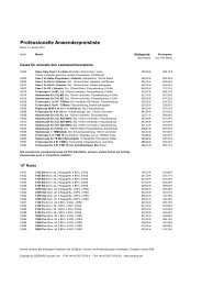
1.1 Signal Path<br />
Eight Inputs – Eight Outputs<br />
The <strong>HDLM8</strong> provides eight Input Busses and eight Outputs. All signals of any physical input may be<br />
mixed together to each Input Bus. Each Output is fixed to its corresponding analog one and will get its<br />
signal by any Input Bus (Figure 1.1).<br />
Practical Options for Sound Adjustment<br />
Besides the gain setting and a compressor-limiter unit, each Input Bus provides extensive filtering possibilities:<br />
Graphic EQ and Parametric EQ to equalize room <strong>acoustic</strong>s, Shelving EQ for low and high<br />
correction and a high pass filter for small speaker matching. Beyond that, all busses may be linked<br />
together, both internally and network-wide in four groups.<br />
These functions except the Graphic EQ are provided by each Output additionally. So you can practically<br />
spread tasks to several assistants (e.g. the band’s sound engineer for Input EQ next to the PA operator<br />
for Output EQ).<br />
1 Field Programming Gate Array; reconfigurable logic elements<br />
7
Figure 1.1: Signal Path<br />
Revolutionary Simple Loudspeaker Configuration<br />
From the viewpoint of a <strong>HDLM8</strong> user, multi-path loudspeaker systems are treated as closed and easyto-handle<br />
single active systems. Cross-over frequencies, equalization and power information are bundled<br />
by the manufacturer in a loudspeaker library. The library is locked and cannot be modified. If you<br />
own the full version of the <strong>HDLM8</strong>, you may add additional loudspeaker systems comfortably using a<br />
proprietary description language.<br />
1.2 Installation and Heat Dissipation<br />
Thanks to the special construction of the enclosure, there is no built-in fan. Critical components are<br />
internally tied up to the chassis using a heat conducting pad.<br />
Take care on sufficient heat dissipation of the top cover. The enclosure is used<br />
as a heat sink and may become hot.<br />
1.3 Restoring after Power Failure<br />
In the case of a power failure, all parameters will be restored automatically. The <strong>HDLM8</strong> saves changes<br />
after approx. five seconds to its internal memory.<br />
8
1.4 dBu, dBV, dBFS and dBGR<br />
To avoid any confusion, the dB-units used will be explained below.<br />
1.4.1 dBu vs. dBFS<br />
The unit dBu 2 describes the logarithmic voltage ratio with a reference voltage of ≈ 0, 775V and is known<br />
in common parlance as the dB in case of audio signal voltage 3 . Every audio device is subject to processing<br />
a maximum signal level before distortion. This value corresponds to 0dBF S (=Full Scale).<br />
The <strong>HDLM8</strong> can process a maximum signal level of 21dBu (Table 1.1).<br />
Positive dBFS Values<br />
Table 1.1: dBu vs. dBFS in the <strong>HDLM8</strong><br />
dBu dBFS<br />
21 0<br />
4 -17<br />
0 -21<br />
Values above 0dBF S are not possible in analog terms. But the <strong>HDLM8</strong> has the ability to reach any level<br />
without distortion, internally. Levels above 0dBF S will be effectively limited by the output limiters.<br />
dBm<br />
The dBm refers to 1 milliwatt. Underlying an impedance of 600Ω, one can equate the dBm with the<br />
dBu. This unit is not used in the audio engineering, but can be displayed by the <strong>HDLM8</strong>. In addition,<br />
the output drivers of the <strong>HDLM8</strong> are very low-impedance and would drive 600Ω loads without loss.<br />
1.4.2 dBV<br />
The unit dBV refers to 1V and has its primary use in home theatre. The <strong>HDLM8</strong> has the possibility to<br />
display this unit also.<br />
1.4.3 dBGR<br />
The dBGR (=Gain Reduction) describes the magnitude of gain reduction of a compressor-limiter unit.<br />
While 0dBGR means no difference in level, 6dBGR corresponds to the half signal level.<br />
1.5 Definition of Terms<br />
For a better understanding of the conceptual design, some important terms are described below.<br />
1.5.1 Project<br />
All individual settings concerning Input Busses and Outputs will be stored in a Project 4 file. There is no<br />
restriction in quantity. Settings in the Device Menu are globally effective and are not part of a project<br />
file.<br />
2 u=unloaded, in contrary to dBm=reference power of 1 milliwatt<br />
3 There is a reference value frequently mentioned, like +4dBu, describing a nominal level meaning 100% plus head room.<br />
4 frequently called Preset in the past<br />
9
FULL<br />
VERSION<br />
1.5.2 Loudspeaker<br />
A Loudspeaker contains all relevant speaker data: cross-over frequencies, offset delays, impedances, power<br />
and equalization settings. It contains up to four single speaker paths with individual labels like HIGH,<br />
LOW, MID and SUB. After that, a Loudspeaker allocates multiple Outputs if required.<br />
All Loudspeakers are compiled to the Loudspeaker Library hierarchically and are or may be protected<br />
using a code. The <strong>HDLM8</strong> comes with a factory-made Loudspeaker Library, including all Loudspeakers<br />
by <strong>SEEBURG</strong> <strong>acoustic</strong> <strong>line</strong>.<br />
1.5.3 Loudspeaker Editor<br />
Loudspeakers will be defined using a proprietary description language using the Loudspeaker Editor tool.<br />
The tool is only available by the web interface. If the Loudspeaker is protected by a code, the description<br />
will be hidden to the user.<br />
1.5.4 Input Bus<br />
An Input Bus is an internal input channel, working independently of the physical inputs. Any physical<br />
input may be mixed together to one Input Bus. There are eight Input Busses in the <strong>HDLM8</strong>.<br />
1.5.5 Output<br />
An Output is an output channel, which is fixed to its dedicated physical analog output.<br />
1.6 FAQ – Frequently Asked Questions<br />
1.6.1 Why is there no Low Pass Filter (LPF)?<br />
The user configurable EQs are only subject for correcting the final system. Using a low pass filter, one<br />
might misuse this as an cross-over filter. Thus, the entire conception of the <strong>HDLM8</strong> would be destroyed.<br />
Cross-over filters (including low pass) are only available in the Loudspeaker Library.<br />
1.6.2 Why can’t I set a particular Tweeter Louder?<br />
The conception specifies closed loudspeaker systems, which provide factory-made, <strong>line</strong>ar frequency response.<br />
This work is done by engineers with professional measuring equipment and long lasting experience.<br />
If one could re-adjust a single property of that, the whole character would be lost. In addition,<br />
this would shift the effective cross-over frequencies.<br />
10<br />
Never adjust the volume of a single speaker path (like a tweeter) at the amplifier!<br />
Always use equalization, which will affect the whole loudspeaker system (keeping<br />
important properties like the relative phase)!
2 Connections<br />
2.1 Power Supply<br />
The <strong>HDLM8</strong> has a built-in universal power supply, which will work at all voltages worldwide between<br />
90 and 264 volt and a frequency of 47 to 440 hertz.<br />
Thanks to the Neutrik PowerCon, the power cord is mechanically safe connected to the <strong>HDLM8</strong>.<br />
The PowerCon connector must not be engaged or disengaged under live. To<br />
power off the <strong>HDLM8</strong>, one should unplug the socket of the outlet. Alternatively,<br />
one might use an outlet strip with switch.<br />
2.2 Analog Inputs and Outputs<br />
The inputs and outputs, utilizing Neutrik XLR receptacles, meet the standard AES14-1992. The maximum<br />
RMS voltage is 21 dBu. The output impedance of both pin 2 (hot) and pin 3 (cold) are highly<br />
balanced. Thus, interferences may be filtered out very efficiently in the next device.<br />
Metal film resistors and high-grade operational amplifiers deliver outmost noise-free and distortion-less<br />
audio signal. The outputs are dc-coupled, so there are no capacitors in the output signal path.<br />
2.2.1 Unbalanced Devices<br />
It is strongly recommended to use the analog inputs and outputs only with balanced devices. The use<br />
with unbalanced devices may predict in noisy and/or distorted audio. To prevent noise and hum, pin 1<br />
is connected to the enclosure and is used only for shielding, as proposed in AES14-1992.<br />
2.2.2 Auto Muting on Power Failure<br />
The analog outputs each have a relay. In order to avoid loud clunk noise, the outputs will be switched<br />
off if the power supply is interrupted.<br />
When powered off, pin 2 and 3 are terminated against a 47 ohms resistor to prevent humming on<br />
connected devices.<br />
This function is disabled after activation of the Service Mode (see Page 24)!<br />
2.3 AES/EBU Digital Input FULL<br />
VERSION<br />
The two-channel digital input complies with the standard AES3. It is isolated via transformer. The<br />
audio signal will be converted to the internal sampling frequency by an Asynchronous Sample Rate<br />
Converter, which is implemented in the FPGA. Thus, jitter will be filtered out effectively. Latency is<br />
only 48 samples. Sampling frequencies between 32 and 96kHz are supported.<br />
11
FULL<br />
VERSION<br />
2.4 Optional ADAT Optical Interface FULL<br />
VERSION<br />
With a hardware option, the <strong>HDLM8</strong> can be expanded with an ADAT interface to eight additional<br />
inputs. After that, the <strong>HDLM8</strong> becomes an excellent output converter (D/A) and equalizer for digital<br />
mixing desks.<br />
Ask your dealer for more information about this option.<br />
2.5 <strong>SEEBURG</strong> Remote Interface (EIA-485)<br />
The <strong>HDLM8</strong> can be used as a master in alarm systems. Communication is done over a two-wire cable<br />
with standard connectors. Due to the low transmission rate, distances up to 2000 meters can be realized.<br />
Individually developed function modules are available on request directly from <strong>SEEBURG</strong> <strong>acoustic</strong> <strong>line</strong>.<br />
2.6 USB Interface<br />
The built-in USB 2.0 interface is used for:<br />
• Importing and Exporting of Projects and Loudspeakers<br />
• Loading wave files to the internal Wave Player 1<br />
• Firmware Updates<br />
Use standard USB sticks with FAT32 file system.<br />
The interface is protected by a self-healing 500mA fuse.<br />
2.7 Ethernet Interfaces with Built-in Switch<br />
Via the Ethernet interfaces, one or multiple computers may be connected to configure the <strong>HDLM8</strong>. The<br />
configuration is via web interface, making special software installation unnecessary.<br />
Use cable of category CAT-5e with RJ45 connectors (see Page 36).<br />
1 planned in version 1.1<br />
12
3 <strong>Operation</strong><br />
The handling of the display menus is divided consistently in navigation using the cursor buttons and<br />
value input using the rotary encoder wheel. Additionally, there are dedicated buttons for Mute and EQ.<br />
3.1 Home Page with Main Menu<br />
After powering up the <strong>HDLM8</strong>, the home page appears on the display. On account of large fonts this<br />
page is easy to read, even from a distance.<br />
Home Page<br />
Channel Status<br />
3.2 Navigation<br />
On the home page, the project name, the device name, the IP address<br />
and the status of all channels is shown. Use the cursor buttons to highlight<br />
a menu item. Use Enter to invoke the appropriate function.<br />
On the Channel Status section, each Input Bus or Output is shown as<br />
a coloured square (Table 3.1). Use the Mute, EQ or Enter buttons to<br />
affect the corresponding action.<br />
Table 3.1: Meaning of the Status Indicators<br />
Appearance Indication<br />
Gray No Signal<br />
Green Signal > -40dBu<br />
Red Signal > -1dBFS<br />
Blue Gain Reduction<br />
Red Frame Muted<br />
Blue Frame Selected<br />
Red-Blue Frame Selected, Muted<br />
Select a menu entry using the cross-shaped cursor buttons (Figure 3.1). On selection, the item will<br />
appear blue framed or backgrounded. Use the Enter button to invoke the appropriate menu. To go<br />
back, use the Exit button (Figure 3.2).<br />
Permanent holding down of a button leads to key repeat, similar as a computer keyboard.<br />
Some menu entries end with three points ("..."), as an indication for another menu beyond that<br />
(Figure 3.3).<br />
13
Figure 3.1: Cursor Buttons<br />
Figure 3.2: Input Buttons<br />
To return to the home page, hold down the Exit button for three seconds.<br />
3.3 Input of Values<br />
Variable properties are usually highlighted in green. Use the wheel (Figure 3.4) to change a value.<br />
3.3.1 Increasing the Number of Steps<br />
• ENT ER + W HEEL = × 10<br />
You may accelerate the input by a factor of ten. Hold down the Enter button while turning the wheel.<br />
3.4 Confirm Changes<br />
For most properties, the change of a value takes place in real time. However, there are properties which<br />
would make no sense to take effect immediately. These are displayed with a yellow background instead<br />
and changes will only be valid after pressing the Enter button.<br />
3.5 Function Buttons MUTE and EQ<br />
Press the Mute button to mute or un-mute a selected Input Bus or Output. Press EQ to invoke the EQ<br />
page (Figure 3.5).<br />
3.6 Mute All Immediately<br />
14<br />
• MUT E + ENT ER = MUT EALL
3.7 Key Lock<br />
3.7.1 Lock<br />
ENTER<br />
EXIT<br />
Figure 3.3: Navigation<br />
Figure 3.4: Rotary Encoder<br />
To get all Outputs muted immediately, press Enter while holding down the Mute<br />
button (Figure 3.6).<br />
• EQ + ENT ER = KEY LOCK<br />
Figure 3.6: All Outputs Muted<br />
Press Enter while holding down EQ (Figure 3.7). The function is available only on the home page.<br />
3.7.2 Un-lock<br />
Again, press Enter while holding down EQ. The lock will be canceled.<br />
15
3.8 Text Input<br />
Figure 3.5: Function Buttons<br />
Figure 3.7: Key Lock<br />
Text input fields are green backgrounded having a yellow cursor (Figure 3.8). Use the horizontal cursor<br />
buttons to move the cursor left or right. Use the wheel to change the character at the cursor. To get a<br />
space character, just move to the most right.<br />
Usually, changes will take effect immediately, so there is no need to confirm.<br />
3.8.1 Delete Characters<br />
Figure 3.8: Text Input<br />
Hold down Enter while turning the wheel. According to the rotation, characters before or after the<br />
cursor will be deleted.<br />
3.8.2 Predefined Keywords<br />
Where appropriate, the <strong>HDLM8</strong> offers a small list of predefined keywords below a text input field. Use<br />
the list to assemble a complete label in seconds without the need of wheeling in character by character.<br />
16
3.9 Fast Navigation for the Advanced User<br />
Combine the cursor buttons with the wheel to move on faster. Hold down a button while turning the<br />
wheel. The selection follows according to the direction of rotation.<br />
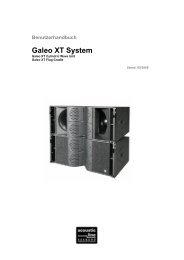
3.10 Structure<br />
The following diagram shows the structure of the menus presented on the display of the <strong>HDLM8</strong>.<br />
Figure 3.9: Structure<br />
17
3.11 Project Management<br />
Name of Project<br />
Project Menu<br />
To invoke the project menu, move the selection to the first entry of the<br />
home page and confirm with Enter.<br />
The asterisk in the right indicates that changes have been made and<br />
disappears after saving again.<br />
Select a menu entry using the cursor buttons and confirm with Enter.<br />
In the following, the individual properties of the Project Menu are described.<br />
3.11.1 New Project<br />
Input of Project Name<br />
3.11.2 Loading<br />
Load a Project<br />
A new project requires necessarily a label. Using the wheel, enter the<br />
name character by character and confirm with Enter.<br />
After creating a new project, all Outputs will be muted and set to Direct<br />
Out. All EQs will be set to flat.<br />
Select a project from the list. Confirm with Enter.<br />
The list is sorted alphabetically and by number of loading: often used<br />
projects are shown first.<br />
Dependent of the setting Mute On Project Load, all Outputs will mute (see page 23). You have to<br />
un-mute them manually.<br />
18
3.11.3 Saving<br />
Overwrite a Project<br />
Save a Project<br />
3.11.4 Deleting<br />
Delete Projects<br />
Hint: the current loaded project cannot be deleted.<br />
3.11.5 Project Import from USB<br />
Show Files of USB stick<br />
Enter a new name using the wheel or select a project from the list you<br />
want to overwrite. Confirm with Enter.<br />
The action will be confirmed with a message.<br />
Select one or more projects using the cursor buttons and the wheel.<br />
Confirm with Enter. All projects tagged with a green check will be<br />
deleted.<br />
Plug in an USB stick into the <strong>HDLM8</strong> and confirm the message USB<br />
device inserted?. The USB device will be searched on its top level for<br />
files having the .hdlm8 extension.<br />
19
Import Projects<br />
Import Completed<br />
3.11.6 Project Export to USB<br />
20<br />
Export Projects<br />
Export<br />
Export Completed<br />
Use the cursor buttons to select and choose one or more projects using<br />
the wheel. After confirmation with Enter, the tagged files will be imported<br />
and stored permanently on the <strong>HDLM8</strong>.<br />
If there are new Loudspeakers used by the importing project files, they<br />
will also be loaded into the Loudspeaker Library.<br />
Do not remove the USB stick before you have confirmed this message<br />
with Enter.<br />
Use the cursor buttons to select and choose one or more projects using<br />
the wheel. After confirmation with Enter, the tagged projects will be<br />
stored to the USB device.<br />
Wait for the operation to be completed.<br />
Additionally, the exported file contains all Loudspeakers used in the corresponding<br />
project, so you may import this file on any <strong>HDLM8</strong> without<br />
trouble.<br />
Do not remove the USB stick before you have confirmed this message<br />
with Enter.
3.11.7 Write Protection<br />
Protect Projects<br />
Use the Security menu to protect projects from overwriting accidentally.<br />
There are two modes: a simple Read Only flag and protection using a<br />
lock code (four digits).<br />
The write protection will not take effect before saving the project!<br />
21
3.12 Device Settings<br />
The properties of the Device Settings menu are stored independently from the current project. Changes<br />
will be saved internally within five seconds.<br />
Invoke the Device Settings Menu<br />
Device Settings<br />
To invoke the Device Settings menu, select the second item on the home<br />
page and confirm with Enter.<br />
Choose a menu item.<br />
In the following, the individual properties of the Device Settings menu are described.<br />
3.12.1 Amplifiers<br />
These are important parameters to the automatic calculation of the output limiters. Set the appropriate<br />
gain of the connected amplifier to each channel.<br />
Amplifiers<br />
The eight rows correspond to the eight physical outputs. Optionally, you<br />
may specify the peak output voltage Vpeak of the amplifier. The <strong>HDLM8</strong><br />
will ensure that the output signal will never exceed this limit, even if<br />
there are larger values in the loudspeaker settings. By that, amplifiers<br />
without or with insufficient limiters may be used safely. Enter this value<br />
only if you know that your amplifiers do not have clean working limiters.<br />
Hint: the Vpeak limiter provides additional security, but always at the expense of dynamics 1 .<br />
It is important that the amplifiers connected deliver exactly the same gain set<br />
as in the Amplifiers Menu. Adjust the volume control on the amplifiers always<br />
to 0dB (usually turned up full).<br />
With incorrect settings, the speakers are not protected by the limiter! See the<br />
manual for your amplifiers to find out the actual gain.<br />
1 The corresponding RMS limiter has a crest factor of 12dB.<br />
22
3.12.2 Delay Unit, Temperature<br />
Set the average ambient temperature. This will be used to calculate the delay for given distance in the<br />
Output Properties. Altitude and air pressure information were omitted, as they have only a very small<br />
influence on the speed of sound in contrast to the temperature.<br />
The unit for the delay can be selected between meters and feet. Depending on the unit, the temperature<br />
is specified in degrees Celsius or Fahrenheit.<br />
3.12.3 Device Name<br />
Device Name<br />
3.12.4 Info<br />
Wheel-in a name for the device. This will be used to recognize the unit<br />
on the network and on the home page display. Changes will take effect<br />
immediately.<br />
The info page shows among other things the version of the firmware.<br />
3.12.5 Update<br />
Firmware Update<br />
If you received an update file from the manufacturer, you may load this<br />
from the USB stick at this point. The top level of the USB device will<br />
be searched for the newest version.<br />
All outputs will mute. This process takes about five minutes. After<br />
completion, the <strong>HDLM8</strong> will reboot and reactivate its outputs.<br />
Do not interrupt the ongoing update process!<br />
Provide a stable power supply!<br />
An interruption may cause that the device no longer works. This can only be<br />
restored by the manufacturer or an authorized service center.<br />
3.12.6 Mute On Project Load<br />
Mute On Project Load<br />
If this function is activated (default on new machines), any Output will<br />
be muted after loading a new project. Otherwise, the last saved mute<br />
state will be restored.<br />
23
FULL<br />
VERSION<br />
FULL<br />
VERSION<br />
3.12.7 Service Mode<br />
The Service Mode is not suitable for normal operation. Among other things, it turns off the automatic<br />
relay shutdown of the outputs during power loss. This can lead to loud clunk noise and may destroy<br />
your speakers! Use the Service Mode service mode only if you consider the circumstances. Turn off your<br />
amplifiers before the <strong>HDLM8</strong> shuts down!<br />
This function is not saved, and after re-powering always disabled by default.<br />
3.13 Network and Digital Interfaces Menu<br />
Invoke the Network Menu<br />
Network Menu<br />
To invoke the Network Menu, select the third item on the home page<br />
and confirm with Enter.<br />
Enter the IP address of the <strong>HDLM8</strong>. Each device needs an individual<br />
IP address (see page 35).<br />
Changes will take effect after confirmation with Set.<br />
The settings Gateway and Netmask are not necessary for normal operation 2 .<br />
3.13.1 Digital Interfaces<br />
Digital Interfaces Menu<br />
In the following, the corresponding functions will be described.<br />
3.13.2 Redundancy Mode (Fallback)<br />
Any available digital input/output may be set up in this menu.<br />
Analog inputs will be ignored, if a valid digital signal is present. In the case of losing the digital signal,<br />
the <strong>HDLM8</strong> will switch back to the analog signal immediately without interruption.<br />
2 Network experts will use these parameters to control the <strong>HDLM8</strong> over the Internet.<br />
24
Prerequisites<br />
Assign at least one analog and one digital physical input to an Input Bus. In Fallback-Mode (if digital<br />
is lost), the <strong>HDLM8</strong> will show Digital? on the home screen (Figure 3.10).<br />
3.13.3 Optical Input (optional)<br />
Figure 3.10: Fallback in Redundancy Mode<br />
Use the wheel to tell the <strong>HDLM8</strong> which digital input format is used. ADAT will take eight tracks, but<br />
is fixed to 48kHz sample rate. SPDIF will take two tracks and may be feed with a sample rate between<br />
32kHz and 96kHz.<br />
The physical AES/EBU interface (XLR) cannot be used at the same time, if the<br />
optical input is set to SPDIF or if a valid ADAT-Signal is present.<br />
The incoming digital signal will always be up-sampled by the internal low-latency Sample Rate Converter<br />
to 96kHz.<br />
3.13.4 Optical Output (optional)<br />
Set this function to Loop for using the optical output as a latency-free loop-trough of the AES/EBU<br />
input or the optical input (SPDIF or ADAT). Additionally, assign any pair of the Output Map to send<br />
the <strong>HDLM8</strong> outputs as a digital 24bit/96kHz SPDIF signal.<br />
25<br />
FULL<br />
VERSION<br />
FULL<br />
VERSION
3.14 Input Bus Map<br />
Channel Status<br />
Input Bus Map<br />
Input Bus Map with Mute<br />
3.14.1 dB Scales<br />
Miscellaneous dB Scales<br />
3.15 Input Bus Properties<br />
Input Bus Properties Menu<br />
Select a channel of the first row in the Channel Status section on the<br />
home page and confirm with Enter.<br />
The screen changes to the Input Bus Map. The selected channel is highlighted.<br />
Below each row, a green <strong>line</strong> is shown, which indicates the level meter of<br />
the bus. Activity of the compressors are indicated with blue <strong>line</strong>s coming<br />
from the right. Channels without any input assigned will appear black,<br />
without the blue background.<br />
At the bottom of the screen, there is a dB scale with selectable units.<br />
Use the cursor buttons to select a channel. Use the Mute button to turn<br />
a channel on or off. To invoke the EQ page, press the EQ button. Use<br />
Enter to invoke the Input Bus Properties menu of the corresponding<br />
channel.<br />
Use the cursor down button to move the selection to the dB scale at the<br />
bottom of the screen. Use the wheel to change the unit (see page 9).<br />
Choose a menu item.<br />
In the following, the individual items of the Input Bus Properties menu are described.<br />
26
3.15.1 Label<br />
Input Bus Label<br />
Wheel-in a label for the channel. Changes will take effect immediately.<br />
For rapid naming, some common predefined keywords are suggested. Use the list to assemble a complete<br />
label in seconds.<br />
Input Bus Label Keywords<br />
Input Bus Label Keywords<br />
3.15.2 Physical Inputs<br />
Physical Inputs<br />
Choose a keyword and confirm with Enter.<br />
The keyword will be appended. A space is created automatically.<br />
Select the physical inputs to mix on this Input Bus using the cursor<br />
buttons and the wheel. Changes take effect immediately.<br />
Please note that depending on the configuration of the <strong>HDLM8</strong>, not<br />
all physical inputs are available. Not available physical inputs will be<br />
displayed gray.<br />
Hint: the mix for the physical input channels is always 1:1, without any correction.<br />
3.15.3 Gain<br />
Set the gain for this channel. Changes take effect immediately. Please note the × 10 mode, as described<br />
on page 14.<br />
27
FULL<br />
VERSION<br />
3.15.4 Polarity<br />
Set the signal polarity for this channel. REV indicates change in polarity. Changes take effect immediately.<br />
3.15.5 Dynamics<br />
Limiter<br />
Compressor with Knee<br />
Set the compressor (or limiter at ratio=∞) using the Ratio and Threshold<br />
parameters. The unit of the threshold corresponds to the unit of the dB<br />
scale, if applicable. To deactivate any compression, set Threshold to its<br />
maximum value or set Ratio to 1.<br />
Control the overflow of RMS to peak using Overshoot in dB. This may<br />
be targeted to determine the Crest Factor.<br />
To get a smooth compression response, use the Knee value. The soft<br />
knee property provides a soft increase of the ratio for n dB around the<br />
Threshold value. This is not available if the Ratio is set to ∞.<br />
Hint: User adjustable dynamics are provided in the Input Busses only. The output limiters will always<br />
be set automatically to prevent misuse or incorrect operation.<br />
3.15.6 Local Link<br />
With Local Link, you may group all parameters of the Input Busses except Mute. Use the wheel to set<br />
one of four link groups and confirm with Enter. If another Input Bus is assigned to the same group, then<br />
all parameters will be copied to this channel. All future changes lead to change the channels assigned to<br />
the same group.<br />
For example, to achieve a stereo linking for Input Bus 1 and 2, set both channels to the same link group.<br />
3.15.7 Network Link<br />
With Network Link, you may group all parameters of the Input Busses across multiple devices on the<br />
connected network. The operation is the same as Local Link. Any number of <strong>HDLM8</strong> may be linked<br />
together, provided they are in the same network 3 .<br />
3 To network experts: data is sent via unidirectional UDP broadcast.<br />
28
3.16 Input Bus EQ<br />
Input Bus EQ<br />
3.16.1 Graphic EQ<br />
Graphic EQ<br />
3.16.2 Parametric EQ (PEQ)<br />
Parametric EQ<br />
3.16.3 Shelving EQ<br />
Shelving EQ<br />
Invoke the Input Bus EQ using the EQ button. Make sure that an Input<br />
Bus was selected previously.<br />
The green curve shows the resulting frequency response of all EQs in<br />
this channel, independent of the shown handles.<br />
There are four tabs on the top for the sub pages Graphic EQ, Parametric<br />
EQ, Shelving EQ and High Pass Filter. Use the left and right cursor<br />
buttons to activate the appropriate page. Use the cursor down button<br />
to reach the functional section.<br />
Choose the frequency using the horizontal cursor buttons and set the<br />
gain with the wheel. (Re-)activate an EQ with Bypass. Use Flat All to<br />
reset all gain settings.<br />
Choose one of five EQ handles using the horizontal cursor buttons. Depending<br />
on the selected menu item, set the gain, frequency or quality Q<br />
using the wheel. (Re-)activate all parametric EQs using Bypass PEQ.<br />
Switch single EQs on or off with Enabled. Flat All leads to reset all<br />
parametric EQs to zero gain.<br />
Use the horizontal cursor buttons to select the low shelf or the high shelf<br />
EQ. Depending on the selected menu item, set the gain or frequency<br />
using the wheel. (Re-)activate an EQ with Bypass. Use Flat All to reset<br />
all gain settings.<br />
The handle shows the frequency position, at which half the gain is<br />
achieved.<br />
29
3.16.4 High Pass Filter (HPF)<br />
High Pass Filter<br />
3.17 Output Map<br />
30<br />
Channel Status<br />
Output Map<br />
Output Map with Delay<br />
Set the frequency and select a type (Table 3.2). Switch the filter on or<br />
off with Bypass HPF.<br />
The handle shows the −3dB position.<br />
Table 3.2: Filter Types in the High Pass Filter<br />
Label Description<br />
BW12 Butterworth 12dB/oct.<br />
LR12 Linkwitz-Riley 12dB/oct.<br />
BW24 Butterworth 24dB/oct.<br />
LR24 Linkwitz-Riley 24dB/oct.<br />
Select a channel of the lower row in the Channel Status section on the<br />
home page and confirm with Enter.<br />
The screen changes to the Output Map. The selected channel is highlighted.<br />
Below each row, a green <strong>line</strong> is shown, which indicates the level meter of<br />
the physical output channel. Activity of the limiters are indicated with<br />
blue <strong>line</strong>s coming from the right. Channels, which are part of a Loudspeaker,<br />
will always be selected together. Parameters can be changed<br />
only on a complete loudspeaker system.<br />
At the bottom of the screen, there is a dB scale with selectable units.<br />
Use the cursor buttons to select a channel. Use the Mute button to<br />
switch a complete Loudspeaker on or off (a red M symbol will appear<br />
on mute). To invoke the EQ page, press the EQ button. Use Enter to<br />
invoke the Output Properties menu of the corresponding loudspeaker.<br />
If assigned, alternately the loudspeaker’s name and the label is shown.<br />
If there was set any delay, a green D symbol will appear.<br />
In the right column, the number of the physical output is shown and at<br />
its left, if any, the speaker path (Table 3.3).<br />
Unconfigured channels are shown and handled as Direct Out. This means fullrange<br />
signal. Make sure that it does not reach a speaker which could be damaged!
3.17.1 dB Scales<br />
Miscellaneous dB Scales<br />
Table 3.3: Specified key words for types (paths) of speakers<br />
Key Word Path<br />
empty Self-powered Loudspeaker or miscellaneous device (full-range)<br />
HIGH Tweeter<br />
MID Mid-range speaker<br />
LOW Low-mid-range speaker<br />
SUB Subwoofer<br />
3.18 Output Properties<br />
Output Bus Properties Menu<br />
Use the cursor down button to move the selection to the dB scale at the<br />
bottom of the screen. Use the wheel to change the unit (see page 9).<br />
At the top of the page, you see all relevant signal level metering to the<br />
according Loudspeaker and its physical outputs.<br />
Choose a menu item.<br />
In the following, the individual items of the Output Properties menu are described.<br />
3.18.1 Label<br />
Output Label<br />
See page 27 for further features on this page.<br />
Wheel-in a label for the loudspeaker. Changes will take effect immediately.<br />
31
3.18.2 Loudspeaker<br />
Loudspeaker Library<br />
Loading a Loudspeaker<br />
Choose a loudspeaker from the list for loading it to the current channel.<br />
Confirm the message. The loudspeaker will be loaded and muted. In<br />
case of need for more channels for the loaded loudspeaker, one ore more<br />
of the following channels may be freed from the Output Map.<br />
The order of the single speakers is defined from high to low. You can only set the start channel of the<br />
first (highest) speaker of the loudspeaker.<br />
3.18.3 Input Bus<br />
Check each time you configure a new loudspeaker the Output Map and make<br />
sure that each speaker is connected to the correct output channel.<br />
Select the Input Bus number which shall feed its signal to this channel (respectively Loudspeaker).<br />
Confirm with Enter.<br />
3.18.4 Gain<br />
Set the gain for this channel. Changes take effect immediately. Please note the × 10 mode, as described<br />
on page 14.<br />
3.18.5 Polarity<br />
Set the signal polarity for this channel. REV indicates change in polarity. Changes take effect immediately.<br />
3.18.6 Delay<br />
Set the delay as a distance in meter or feet. The temperature and unit as set in the Device Settings<br />
menu will take account. If set, a green D symbol will appear in the corresponding row of the Output<br />
Map. Changes take effect immediately.<br />
To deactivate the delay, set the value to zero.<br />
32<br />
Since changes take effect immediately, there may appear noise or interruption on<br />
the outputs while re-adjusting the distance.
3.18.7 Local Link<br />
With Local Link, you may group all parameters of the Outputs except Mute. Use the wheel to set one<br />
of four link groups and confirm with Enter. If another Output is assigned to the same group, then all<br />
parameters will be copied to this channel. All future changes lead to change the channels assigned to<br />
the same group.<br />
Note, that the linking functions in the Output Map are independent from those ones in the Input Bus<br />
Map.<br />
3.18.8 Network Link FULL<br />
VERSION<br />
With Network Link, you may group all parameters of the Outputs across multiple devices on the connected<br />
network. The operation is the same as Local Link. Any number of <strong>HDLM8</strong> may be linked<br />
together, provided they are in the same network.<br />
3.19 Output EQ<br />
Note that all EQ settings will always take effect to the whole Loudspeaker. This ensures that all paths<br />
are equally modified in-phase. The drawn resulting frequency curve shows all EQ settings made in the<br />
Output EQ. Settings made in the Loudspeaker setup, including cross-over frequencies, are not shown<br />
here.<br />
Output EQ<br />
3.19.1 Parametric EQ (PEQ)<br />
Parametric EQ<br />
Invoke the Output EQ using the EQ button. Make sure that an Output<br />
was selected previously.<br />
The green curve shows the resulting frequency response of all EQs in<br />
this channel, independent of the shown handles.<br />
There are three tabs on the top for the sub pages Parametric EQ, Shelving<br />
EQ and High Pass Filter. Use the left and right cursor buttons to<br />
activate the appropriate page. Use the cursor down button to reach the<br />
functional section.<br />
Choose one of four EQ handles using the horizontal cursor buttons. Depending<br />
on the selected menu item, set the gain, frequency or quality Q<br />
using the wheel. (Re-)activate all parametric EQs using Bypass PEQ.<br />
Switch single EQs on or off with Enabled. Flat All leads to reset all<br />
parametric EQs to zero gain.<br />
33
3.19.2 Shelving EQ<br />
Shelving EQ<br />
3.19.3 High Pass Filter (HPF)<br />
High Pass Filter<br />
Use the horizontal cursor buttons to select the low shelf or the high shelf<br />
EQ. Depending on the selected menu item, set the gain or frequency<br />
using the wheel. (Re-)activate an EQ with Bypass. Use Flat All to reset<br />
all gain settings.<br />
The handle shows the frequency position at which half the gain is<br />
achieved.<br />
Set the frequency and select a type (Table 3.2). Switch the filter on or<br />
off with Bypass HPF.<br />
The handle shows the −3dB position.<br />
See the description of the filter types used in the HPF in Table 3.2 on Page 30.<br />
34
4 Network Setup<br />
4.1 <strong>Operation</strong> via Web Browser<br />
Data communication between a Personal Computer and the <strong>HDLM8</strong> is based on TCP/IP Ethernet<br />
technology. Thanks to that, you don’t have to install any additional software on your computer. It is<br />
operated using the Mozilla Firefox browser software 1 .<br />
To connect to the <strong>HDLM8</strong>, open the Mozilla Firefox application and enter the IP address shown in the<br />
display. After about ten seconds, the user interface is ready and the device can now be controlled in real<br />
time.<br />
The system is platform independent and can be used by nearly any operating system, such as Windows,<br />
Mac or Linux. However, it is necessary that the computer has a processor at 2 GHz clock frequency or<br />
higher. Up to ten computers can simultaneously access a <strong>HDLM8</strong>.<br />
A special App for the Apple iPhone, iPod and iPad is sold separately.<br />
4.2 Introduction in IP Addressing<br />
To connect a Personal Computer to the <strong>HDLM8</strong> successfully, you should know how IP addresses are<br />
represented and what they mean.<br />
In an ordinary network at home or in an office, there is often special equipment such as a router which<br />
will assign IP addresses 2 . The automatic procedure is not useful for operation in the environment of<br />
loudspeaker management systems. In order to address devices directly, one needs the manual control<br />
over the network.<br />
4.2.1 Purpose<br />
Similar to a postal address on an envelope, data packets are provided with an identifier, which is the IP<br />
address. Thus a receiver can be clearly identified. It is therefore important that in a closed network a<br />
specific IP address occur only once.<br />
4.2.2 Representation<br />
IP addresses are represented in four single numbers, divided by a dot. Each part is called an octet. The<br />
numbers may be in the range from 0 to 255.<br />
There is a breakdown in public and private address spaces. In the <strong>HDLM8</strong> environment, you will usually<br />
make use of the private address space. Following ranges may be used:<br />
Table 4.1: Private IP Address Space<br />
Start End<br />
192.168.0.1 192.168.255.254<br />
172.16.0.1 172.31.255.254<br />
10.0.0.1 10.255.255.254<br />
1 Get Mozilla Firefox free of charge on http://www.mozilla-europe.org/de/firefox<br />
2 known as DHCP<br />
35
4.2.3 Usage<br />
In a <strong>HDLM8</strong> environment, all IP addresses should match except the last octet, which must be individual.<br />
If not, you will not get a working connection. This concerns also the Network Link Groups between<br />
interconnected <strong>HDLM8</strong> devices. Examples:<br />
Table 4.2: Addressing Examples<br />
IP Address Device<br />
192.168.0.1 Laptop Stage<br />
192.168.0.2 Laptop PA Operator<br />
192.168.0.10 <strong>HDLM8</strong> PA left<br />
192.168.0.11 <strong>HDLM8</strong> PA right<br />
4.3 Utilization of the Network Interface by Third Parties<br />
The <strong>HDLM8</strong> utilizes a fully compatible and real-time capable 10/100Mbps Ethernet Switch with two<br />
ports. This is also ideal for connecting third party networking devices, such as lighting or video equipment,<br />
or for the transmission of audio signals via CobraNet or DANTE. The data packets of the <strong>HDLM8</strong><br />
are relatively small. The communication works stable even in heavy-loaded networks.<br />
36
5 Web Interface<br />
The <strong>HDLM8</strong> may be remote controlled by the web browser software Mozilla Firefox. Enter the IP address<br />
of the <strong>HDLM8</strong> in the URL.<br />
The available parameters are similar to the elements on the display. For a detailed function reference,<br />
refer to Chapter 3.<br />
Please wait until the surface is built up completely before starting the operation<br />
(approximately ten seconds).<br />
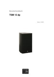
Below, you see screen shots for guidance from the Web Interface. The documentation is available<br />
separately.<br />
Figure 5.1: Loudspeaker Editor<br />
37