An Introduction to Portable CMMs - FARO Asia
An Introduction to Portable CMMs - FARO Asia
An Introduction to Portable CMMs - FARO Asia

Create successful ePaper yourself
Turn your PDF publications into a flip-book with our unique Google optimized e-Paper software.
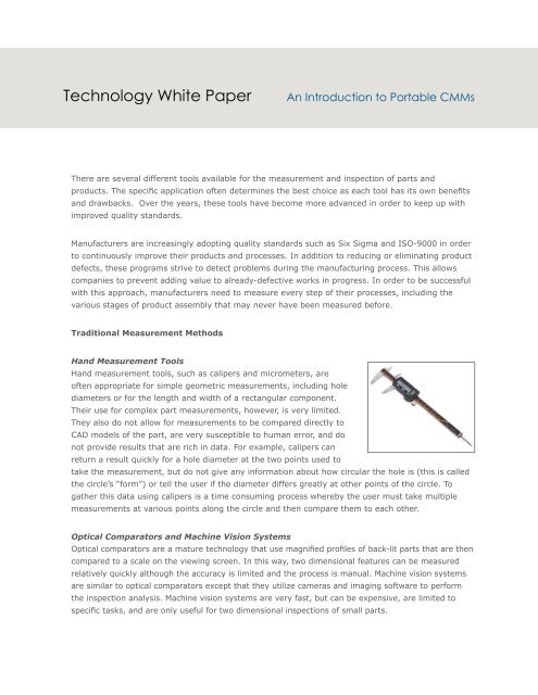
Technology White Paper<strong>An</strong> <strong>Introduction</strong> <strong>to</strong> <strong>Portable</strong> <strong>CMMs</strong>There are several different <strong>to</strong>ols available for the measurement and inspection of parts andproducts. The specific application often determines the best choice as each <strong>to</strong>ol has its own benefitsand drawbacks. Over the years, these <strong>to</strong>ols have become more advanced in order <strong>to</strong> keep up withimproved quality standards.Manufacturers are increasingly adopting quality standards such as Six Sigma and ISO-9000 in order<strong>to</strong> continuously improve their products and processes. In addition <strong>to</strong> reducing or eliminating productdefects, these programs strive <strong>to</strong> detect problems during the manufacturing process. This allowscompanies <strong>to</strong> prevent adding value <strong>to</strong> already-defective works in progress. In order <strong>to</strong> be successfulwith this approach, manufacturers need <strong>to</strong> measure every step of their processes, including thevarious stages of product assembly that may never have been measured before.Traditional Measurement MethodsHand Measurement ToolsHand measurement <strong>to</strong>ols, such as calipers and micrometers, areoften appropriate for simple geometric measurements, including holediameters or for the length and width of a rectangular component.Their use for complex part measurements, however, is very limited.They also do not allow for measurements <strong>to</strong> be compared directly <strong>to</strong>CAD models of the part, are very susceptible <strong>to</strong> human error, and donot provide results that are rich in data. For example, calipers canreturn a result quickly for a hole diameter at the two points used <strong>to</strong>take the measurement, but do not give any information about how circular the hole is (this is calledthe circle’s “form”) or tell the user if the diameter differs greatly at other points of the circle. Togather this data using calipers is a time consuming process whereby the user must take multiplemeasurements at various points along the circle and then compare them <strong>to</strong> each other.Optical Compara<strong>to</strong>rs and Machine Vision SystemsOptical compara<strong>to</strong>rs are a mature technology that use magnified profiles of back-lit parts that are thencompared <strong>to</strong> a scale on the viewing screen. In this way, two dimensional features can be measuredrelatively quickly although the accuracy is limited and the process is manual. Machine vision systemsare similar <strong>to</strong> optical compara<strong>to</strong>rs except that they utilize cameras and imaging software <strong>to</strong> performthe inspection analysis. Machine vision systems are very fast, but can be expensive, are limited <strong>to</strong>specific tasks, and are only useful for two dimensional inspections of small parts.
Coordinate Measuring MachinesCoordinate Measuring Machines (<strong>CMMs</strong>) are mechanical systems designed <strong>to</strong> track a mobilemeasuring probe <strong>to</strong> determine the coordinates of points on a work surface. <strong>CMMs</strong> are comprised offour main components: the machine body including the measurement bed, the measuring probe, thecontrol or computing system, and the measuring software. Machines are available in a wide range ofsizes and designs and with a variety of different probe technologies.The Use of CADMany manufacturers are adopting CMM technology due <strong>to</strong> the prevalence of CAD in productdevelopment. CAD software facilitates the design process and provides manufacturers with virtual3D design models. Manufacturers use CAD software <strong>to</strong> create designs and engineering specificationsfor new products as well as for quantifying and modifying designs and specifications of existingproducts. The use of CAD can shorten the time between designrevisions; current manufacturing practices must accommodate morefrequent product introductions and modifications while satisfyingstringent quality and safety standards. Assembly fixtures andmeasurement <strong>to</strong>ols must be linked <strong>to</strong> the most up-<strong>to</strong>-date CADdesign in order <strong>to</strong> allow production <strong>to</strong> keep up with the rapid pace ofdesign changes.Traditional (Fixed) <strong>CMMs</strong>The first CMM appeared in the early 1960s and was a device with a simple digital read-out thatdisplayed the XYZ position of the machine. Traditional types of <strong>CMMs</strong> include bridge, cantilever, andgantry.Fixed <strong>CMMs</strong> provide very high levels of precision and offer a link <strong>to</strong> the CAD model. However,they require the object being measured <strong>to</strong> be brought <strong>to</strong> the CMM (typically in a temperaturecontrolledroom) and the object must fit within the CMM’s measurement grid. As manufacturedsubassemblies increase in size and become integrated in<strong>to</strong> even larger assemblies, they becomeless portable, thus diminishing the utility of a conventional CMM. Manufacturers must also continue<strong>to</strong> use hand measuring <strong>to</strong>ols, or expensive cus<strong>to</strong>mized test fixtures, in order <strong>to</strong> measure large orunconventionally shaped objects. The fixed CMM is also complex <strong>to</strong> operate, therefore limiting thenumber of potential opera<strong>to</strong>rs and users.<strong>Portable</strong> <strong>CMMs</strong>Many advances in CMM technology have occurred over the decades, including the development ofportable <strong>CMMs</strong>. <strong>Portable</strong> <strong>CMMs</strong> provide all the benefits of traditional <strong>CMMs</strong> but with added flexibility.They are lightweight and can therefore be used anywhere measurement is needed (the machinegoes <strong>to</strong> the part). A controlled environment is not required and operation is very simple. Theyprovide highly accurate results and are robust enough <strong>to</strong> work in a wide range of environments.<strong>Portable</strong> <strong>CMMs</strong> are also typically much less expensive than a traditional CMM.
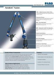
Types of <strong>Portable</strong> <strong>CMMs</strong>There are two main types of portable <strong>CMMs</strong>: articulated arms and laser trackers.Articulated Arms<strong>An</strong> articulated arm determines and records the location of a probe in 3Dspace and reports the results through software. In order <strong>to</strong> calculate theposition of the probe tip, the rotational angle of each joint and the lengthof each segment in the arm must be known. Radial reach when extendedtypically ranges from 2 feet <strong>to</strong> 6 feet (4-foot <strong>to</strong> 12-foot diameter or workingvolume).The angle of each rotating joint within the arm is determined using optical rotary encoders. Theseencoders count rotations incrementally via detection of accurately spaced lines on a glass gratingdisc. The software converts the counts in<strong>to</strong> angle changes. Arms typically have 6 or 7 axes ofrotation, which means the instrument moves throughout a wide range of orientations.Typical applications for an articulated arm are:• Dimensional <strong>An</strong>alysis: Calculate measurements for geometric and GD&T analysis• CAD-Based Inspection: Measure directly against CAD data <strong>to</strong> see real-time deviations• On-Machine Inspection: Inspect parts on the machine <strong>to</strong>ol producing them• First Article Inspection: Measure individual parts <strong>to</strong> compare with nominal data• Alignment: Align parts <strong>to</strong> assess variation in relative position• Reverse Engineering: Digitize parts and objects <strong>to</strong> create fully-surfaced CAD modelsLaser TrackersThe operation of a laser tracker is easy <strong>to</strong> understand: It measures twoangles and a distance. The tracker sends a laser beam <strong>to</strong> a retroreflectivetarget held against the object <strong>to</strong> be measured. Light reflected off thetarget retraces its path, re-entering the tracker at the same position itleft. Retroreflective targets vary, but the most popular is the sphericallymounted retroreflec<strong>to</strong>r (SMR). As light re-enters the tracker, it goes <strong>to</strong> adistance meter that measures the distance from the tracker <strong>to</strong> the SMR.The distance meter may be either of two types, interferometer or absolutedistance meter (ADM).Laser trackers offer extremely high accuracy levels and much larger measurement ranges (hundredsof feet in diameter). They collect coordinate data at very high speeds and require just one opera<strong>to</strong>r.Typical applications for a laser tracker are:• Alignment: Real-time feedback of object positioning• Installation: Lay out / level machine foundation• Part Inspection: Digital record of actual versus nominal data• Tool Building: Set up and inspect <strong>to</strong>ols with only one person• Reverse Engineering: Acquire high-accuracy digital scan data
SummaryDespite the wide range of options in quality measurement <strong>to</strong>ols, portable <strong>CMMs</strong> continue <strong>to</strong> grow inpopularity. Companies are experiencing the accuracy results they need, while gaining the flexibility<strong>to</strong> use the unit wherever and whenever it is most convenient. The savings that result from usingportable <strong>CMMs</strong> include reduced scrap, shorter measurement times, and improved product quality.These savings have allowed companies <strong>to</strong> see a complete return on their portable CMM investment –in many cases within twelve months.www.faro.com • 800.736.0234<strong>FARO</strong> and the <strong>FARO</strong> Logo are registered trademarks and trademarks of <strong>FARO</strong> Technologies, Inc. © 2009 <strong>FARO</strong> Technologies, Inc. All Rights Reserved. SFDC_04MKT_0170.pdf Revised: 10/16/09