ICEpower50ASX2
ICEpower50ASX2
ICEpower50ASX2

You also want an ePaper? Increase the reach of your titles
YUMPU automatically turns print PDFs into web optimized ePapers that Google loves.
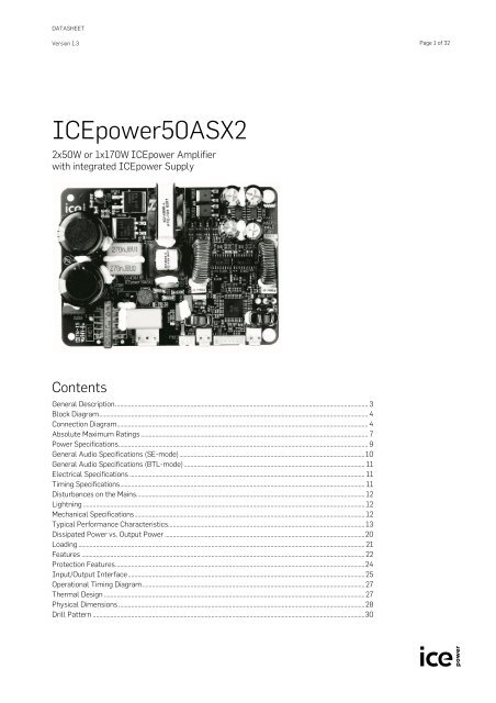
DATASHEETVersion 1.3Page 1 of 32<strong>ICEpower50ASX2</strong>2x50W or 1x170W ICEpower Amplifierwith integrated ICEpower SupplyContentsGeneral Description .............................................................................................................................................................. 3Block Diagram ........................................................................................................................................................................ 4Connection Diagram ............................................................................................................................................................. 4Absolute Maximum Ratings .............................................................................................................................................. 7Power Specifications ............................................................................................................................................................ 9General Audio Specifications (SE-mode) .................................................................................................................... 10General Audio Specifications (BTL-mode) ................................................................................................................. 11Electrical Specifications ................................................................................................................................................... 11Timing Specifications ......................................................................................................................................................... 11Disturbances on the Mains............................................................................................................................................... 12Lightning ................................................................................................................................................................................ 12Mechanical Specifications ................................................................................................................................................ 12Typical Performance Characteristics........................................................................................................................... 13Dissipated Power vs. Output Power ............................................................................................................................. 20Loading ................................................................................................................................................................................... 21Features ................................................................................................................................................................................. 22Protection Features ............................................................................................................................................................ 24Input/Output Interface .................................................................................................................................................... 25Operational Timing Diagram ........................................................................................................................................... 27Thermal Design ................................................................................................................................................................... 27Physical Dimensions .......................................................................................................................................................... 28Drill Pattern .......................................................................................................................................................................... 30
DATASHEET Version 1.3Page 2 of 32<strong>ICEpower50ASX2</strong>2x50W or 1x170W ICEpower Amplifierwith integrated ICEpower SupplySafety Standards ................................................................................................................................................................. 31ESD Warning ......................................................................................................................................................................... 31Packaging and Storing ....................................................................................................................................................... 31Notes ....................................................................................................................................................................................... 32Notice ...................................................................................................................................................................................... 32
DATASHEET Version 1.3Page 4 of 32<strong>ICEpower50ASX2</strong>2x50W or 1x170W ICEpower Amplifierwith integrated ICEpower SupplyBlock DiagramFigure 1: <strong>ICEpower50ASX2</strong> block diagramConnection DiagramFigure 2: <strong>ICEpower50ASX2</strong> connections
DATASHEET Version 1.3Page 5 of 32<strong>ICEpower50ASX2</strong>2x50W or 1x170W ICEpower Amplifierwith integrated ICEpower SupplyThe connector interface of the <strong>ICEpower50ASX2</strong> modules has five industry standard connectors selectedfor long-term reliability.AC Header Specifications (P100)Type: JST B2P3-VHPIN Function Description Type1 Live Live AC Input2 Neutral Neutral AC InputTable 1: AC connector specificationsSpeaker Header Specifications (P101)*Type: JST B2P-VHPIN Function Description Type1 Vo+ Amplifier output channel 1 Output2 GND GND channel1 GNDTable 2: Speaker connector specifications*P101 is not mounted on the BTL-version.Speaker Header Specifications (P104)Type: JST B2P-VHPIN Function Description Type1 Vo+ Amplifier output channel 2 Output2 GND in SE(Vo- in BTL)GND channel2 *Table 3: Speaker connector specificationsGND** This pin is Vo+ (hot) in BTL version and GND in SE versionSignal Header Specifications (P102)Type: JST B7B-PH-K-SPIN Function Description Type7 Vin channel 1 Input signal channel 1 input6 GND Ground terminal for the signal section. GND5 GND Ground terminal for the signal section. GND4 Vin channel 2 Input signal channel 2 Input3 Thermal Thermal monitoring pin Output*2 OC Monitor pin amplifier over current Output*1 Enable Amplifier enable Input/Output*Table 4: Signal connector specifications* See “Features” section on page 18
DATASHEET Version 1.3<strong>ICEpower50ASX2</strong>2x50W or 1x170W ICEpower Amplifierwith integrated ICEpower SupplyPage 7 of 32Absolute Maximum RatingsAbsolute maximum ratings indicate limits beyond which damage may occur.Mains Input Section115V mains settingSymbol Parameter Value UnitsAC max Maximum off-line voltage 132 V ACAC min Minimum off-line voltage 85 1) V ACF Mains frequency range 85V AC - 132V AC 45 – 65 HzTable 6: Absolute maximum ratings, mains input section - 115V setting230V mains settingSymbol Parameter Value UnitsAC max Maximum off-line voltage 264 V ACAC min Minimum off-line voltage 170 1) V ACF Mains frequency range 170V AC - 264V AC 45 – 65 HzTable 7: Absolute maximum ratings, mains input section - 230V setting1) The <strong>ICEpower50ASX2</strong> will operate at lower levels but the output power will be reduced. If the off-line voltageis too low the <strong>ICEpower50ASX2</strong> switches off.Auxiliary SupplySymbol Parameter Value UnitI Vd Maximum current draw from Vd (+25V) 2) 200 mAI Vs Maximum current draw from Vs (-25V) 2) -200 mATable 8: Absolute maximum ratings, auxiliary supply2) If the auxillary supply on the <strong>ICEpower50ASX2</strong> is used with a capacitive load please remember to read thesection “Capacitive Loading of the AUX Supply” in the <strong>ICEpower50ASX2</strong> Designer’s manual.Input SectionSymbol Parameter Value UnitVin channel 1 ,Vin channel 2Maximum voltage range on pin ±3.3 V pTable 9: Absolute maximum ratings, input sectionOutput SectionSymbol Parameter Value UnitsR load Minimum load 3 Ω3)I out Maximum current draw from amplifier output 20 AC L Maximal pure capacitive loading 470 nFTable 10: Absolute maximum ratings, output section.
DATASHEET Version 1.3Page 8 of 32<strong>ICEpower50ASX2</strong>2x50W or 1x170W ICEpower Amplifierwith integrated ICEpower Supply3) The over current protection will act to protect the amplifier. (See ”Protection features”)Thermal SectionSymbol Parameter Value UnitT aMax. operating ambient temperature50O C(tropical conditions)Table 11: Absolute maximum ratings, thermal section
DATASHEET Version 1.3<strong>ICEpower50ASX2</strong>2x50W or 1x170W ICEpower Amplifierwith integrated ICEpower SupplyPage 9 of 32Power SpecificationsUnless otherwise specified. T a =25 O C, f=1kHz, R L =4Ω, 230V mainsSymbol Parameter Conditions Min Typ Max Unitst Pmax Time of maximum rated output power 170W out. No preheating. - 120 - sP T Continuous output power 4) without Thermal stab. @ T a = 25 O C. - 43 - Wthermal shutdown. (SE, 4Ω)Both channels drivenP T Continuous output power 4) without Thermal stab. @ T a = 25 O C. - 30 - Wthermal shutdown. (SE, 8Ω)Both channels drivenP T Continuous output power 4) without Thermal stab. @ T a = 25 O C. - 50 - Wthermal shutdown. (BTL, 4Ω)P T Continuous output power 4) without Thermal stab. @ T a = 25 O C. - 100 - Wthermal shutdown. (BTL, 8Ω)P SMPS Quiescent power consumption (– amplifierEnable pin low - 4 - Wdisabled)P q Quiescent power consumption (amplifier Po = 0W - 7 - Wenabled)η Total power efficiency Po = 100W- 80 - %Po = 170W- 81 -Vd aux ,Vs auxNominal DC voltageAny combination of mainsvoltage and output powerwithin specified ranges.±16 ±25 ±31 VTable 12: Power specifications4) The module is mounted vertically in free air.
DATASHEET Version 1.3Page 10 of 32<strong>ICEpower50ASX2</strong>2x50W or 1x170W ICEpower Amplifierwith integrated ICEpower SupplyGeneral Audio Specifications (SE-version)Unless otherwise specified, f=1kHz, P O =1W, T a =25 O C.Symbol Parameter Conditions Min Typ Max UnitsP OOutput power @ 1%THD+N20Hz < f < 20kHz, both channels driven.(AES17 measurement filter) 5)R L = 4Ω230V ac / 50Hz,115V ac / 50Hz--4745--WP OOutput power @ 10%THD+N20Hz < f < 20kHz, both channels driven.(AES17 measurement filter) 5)R L = 4Ω230V ac / 50Hz,115V ac /50Hz--5754--WP OOutput power @ 1%THD+N20Hz < f < 20kHz, one channel driven.(AES17 measurement filter) 5)R L = 4Ω230V ac / 50Hz,115V ac / 50Hz--5050--WTHD+NTHD+N (4Ω,AES17 measurement filter)6)f = 100Hz, P O =1W - 0.003 0.01 %V N,O Output referenced idle noise A-weighted 15 25 70 µVA V Nominal Voltage Gain f = 1 kHz 20 20.5 21 dBf Frequency response 20Hz - 20kHz, All loads - ±0.1 ±0.5 dBf uUpper bandwidth limit (SE)(-3dB)R L = 8ΩR L = 4Ωf l Lower bandwidth limit (-3dB) R L = All loads - 1.5 - HzZ o Abs. output impedance f = 1kHz - 14 25 mΩZ L Load impedance range 3 4 ∝ ΩD Dynamic range A-weighted (50W, 4Ω) - 120 - dBIMD Intermodulation (CCIF) f =18.5kHz, 1kHz, P O =10W - 0.0007 - %TIM Transient intermodulation (DIM30) P O =10W - 0.007 - %Table 13: General audio specifications, SE mode--13095--kHzkHz5) An Audio Precision AES17 20 kHz 7 th order measurement filter is used for measurements. The frequency 6.67kHz corresponds to the worst-case situation where both 2 nd and 3 rd harmonics are within the audio band.
DATASHEET Version 1.3Page 11 of 32<strong>ICEpower50ASX2</strong>2x50W or 1x170W ICEpower Amplifierwith integrated ICEpower SupplyGeneral Audio Specifications (BTL-version)Unless otherwise specified, f=1kHz, P O =1W, T a =25 O C.Symbol Parameter Conditions Min Typ Max UnitsP OP OOutput power @ 1%THD+N20Hz < f < 20kHz(AES17 measurement filter) 6)Output power @ 10%THD+N20Hz < f < 20kHz(AES17 measurement filter) 6)R L = 4Ω230V ac / 50Hz,115V ac / 50HzR L = 4Ω230V ac / 50Hz,115V ac /50Hzf = 100Hz, P =1W - 0.002 0.005 %THD+N THD+N in 4Ω(AES17 measurement filter) 6) OV N,O Output referenced idle noise A-weighted15 20 70 µV20Hz < f < 20kHzA V Nominal Voltage Gain f = 1 kHz 26 27 28 dBf Frequency response 20Hz - 20kHz, All loads - ±0.2 ±0.6 dBf uUpper bandwidth limit (BTL)(-3dB)R L = 8ΩR L = 4Ωf l Lower bandwidth limit (-3dB) R L = All loads - 1.5 - HzZ o Abs. output impedance f = 1kHz - 18 30 mΩZ L Load impedance range 3 4 ∝ ΩD Dynamic range A-weighted at 170W@4Ω - 125 - dBIMD Intermodulation (CCIF) f =18.5kHz, 1kHz, P O =10W - 0.0002 - %TIM Transient intermodulation (DIM30) P O =10W - 0.003 - %Table 14: General audio specifications, BTL mode6) An Audio Precision AES17 20 kHz 7th order measurement filter is used for measurements. The frequency 6.67kHz corresponds to the worst-case situation where both 2nd and 3rd harmonics are within the audio band.------17015022018010075------kHzkHzWWElectrical SpecificationsUnless otherwise specified, T a =25 O C.Symbol Parameter Conditions Min Typ Max Unitf o Idle switching frequency Idle 500 550 600 kHzf s Switching frequency range (amplifier) Idle to full scale variation 90 - 600 kHzf smps Switching frequency (power supply) - 100 - kHzTable 15: Electrical specificationsTiming SpecificationsSymbol Parameter Conditions Min Typ Max Unitt acdPower supply start up delay.(nominal mains)Table 16: Timing specificationsTime from reaching AC min to all power suppliesare good and amplifier is active.- 700 1000 ms
DATASHEET Version 1.3<strong>ICEpower50ASX2</strong>2x50W or 1x170W ICEpower Amplifierwith integrated ICEpower SupplyPage 12 of 32Disturbances on the MainsThe signal on the mains connection is often very noisy and large surge voltages are present. The<strong>ICEpower50ASX2</strong> is equipped with mains filtering to suppress surges and noise.LightningTo avoid damage of the <strong>ICEpower50ASX2</strong> in case of surges caused by lightning, special care andcomponent selection have resulted in capability of withstanding surges up to 5.5kV.Mechanical SpecificationsDuring development the <strong>ICEpower50ASX2</strong> has passed tough mechanical tests to ensure high reliability.Test Acceleration AmountUnpowered tests: The unit is powered after the test to verify functionality.Random vibration 2g RMS 3x20minBump 10g/16ms, 2-4 Hz 1000 bumps in each of 6 directions 7)Shock 70g/12ms 3 shocks in each of 6 directions 7)Powered tests: The unit is tested with power applied.Sinusoidal vibrations2.5mm, 5-10Hz1g, 10-100HzRandom vibrations 0.01g, 10-20Hz0.7g RMS –3dB/oct, 20-150HzTable 17: Mechanical tests2 hours in each of 3 directions 7)2 hours in each of 3 directions 7)7) 6 directions: (up, down, left, right forward and backward). 3 directions: (up and down, left and right, forward andbackward)
DATASHEET Version 1.3<strong>ICEpower50ASX2</strong>2x50W or 1x170W ICEpower Amplifierwith integrated ICEpower SupplyPage 13 of 32Typical Performance CharacteristicsFrequency Response (SE-version)dBgA+24+23+22+21+20+19+18+17+16+15+14+13+12+11+10+9+8+7+6+5+4+3+2+1-020 50 100 200 500 1k 2k 5k 10k 20k 50k 100kHz+90+80+70+60+50+40+30+20+10+0-10-20-30-40-50-60-70-80-90degFigure 3: Frequency response in 4Ω (green), 8Ω (blue) and open load (red). Top – amplitude.Bottom – phase.Frequency Response (BTL-version)+34+32+30+28+26+24+90+80+70+60+50+40+22+30+20+20dBgA+18+16+10+0-10deg+14-20+12-30+10-40+8-50+6-60+4-70+2-80-020 50 100 200 500 1k 2k 5k 10k 20k 50k 100kHz-90Figure 4: Frequency response in 4Ω (green), 8Ω (blue) and open load (red). Top – amplitude.Bottom – phase.
DATASHEET Version 1.3<strong>ICEpower50ASX2</strong>2x50W or 1x170W ICEpower Amplifierwith integrated ICEpower SupplyPage 14 of 32Harmonic Distortion & Noise (SE-version)10105522110.50.50.20.2%0.1%0.10.050.050.020.020.010.010.0050.0050.0020.0020.001100m 200m 500m 1 2 5 10 20500.001100m 200m 500m 1 2 5 10 20 50 100WWTHD+N vs. Po at 100Hz, 1kHz and 6.67kHz 8) (8Ω). 230Vac/50Hz105THD+N vs. Po at 100Hz, 1kHz and 6.67kHz 8) (4Ω), 230Vac/50Hz105210.5210.50.20.2%0.1%0.10.050.050.020.020.010.010.0050.0050.0020.0020.001100m 200m 500m 1 2 5 10 20500.001100m 200m 500m 1 2 5 10 20 50 100WWTHD+N vs. Po at 100Hz, 1kHz and 6.67kHz 8) (8Ω), 115Vac/50HzdBrA+0-10-20-30-40-50-60-70-80-90-100-110-120-130-140-150-160-1700 2k 4k 6k 8k 10k 12k 14k 16k 18k 20k 22kIdle noise (16K FFT). Residual = 25µV(A).(Relative to 50W into 4 ohm)HzTHD+N vs. Po at 100Hz, 1kHz and 6.67kHz 8) (4Ω), 115Vac/50HzdBrA+0-10-20-30-40-50-60-70-80-90-100-110-120-130-140-150-160-1700 2k 4k 6k 8k 10k 12k 14k 16k 18k 20k 22kHzf = 5kHz. Po = 100mW. 4Ω loading.(Relative to 50W into 4 ohm)Figure 5: Total harmonic distortion & noise (SE).9) An Audio Precision AES17 20 kHz 7th order measurement filter is used for measurements. The frequency 6.67kHz corresponds to the worst-case situation where both 2nd and 3rd harmonics are within the audio band.
DATASHEET Version 1.3<strong>ICEpower50ASX2</strong>2x50W or 1x170W ICEpower Amplifierwith integrated ICEpower SupplyPage 15 of 32Harmonic Distortion & Noise (BTL-mode)10105522110.50.50.20.20.10.10.050.05%%0.020.020.010.010.0050.0050.0020.0020.0010.0010.00050.00050.00020.00020.0001100m 200m 500m 1 2 5 10 20 50 100 200 3000.0001100m 200m 500m 1 2 5 10 20 50 100 200 300WWTHD+N vs. Po at 100Hz, 1kHz and 6.67kHz 8) (8Ω). 230Vac/50HzTHD+N vs. Po at 100Hz, 1kHz and 6.67kHz 8) (4Ω), 230Vac/50Hz105105210.5210.50.20.10.20.10.050.05%%0.020.020.010.010.0050.0050.0020.0020.0010.0010.00050.00050.00020.00020.0001100m 200m 500m 1 2 5 10 20 50 100 200 3000.0001100m 200m 500m 1 2 5 10 20 50 100 200 300WWTHD+N vs. Po at 100Hz, 1kHz and 6.67kHz 8) (8Ω), 115Vac/50HzTHD+N vs. Po at 100Hz, 1kHz and 6.67kHz 8) (4Ω), 115Vac/50Hz+0+0-10-10-20-20-30-30-40-40-50-50-60-60dBrA-70-80-90-100dBrA-70-80-90-100-110-110-120-120-130-130-140-140-150-150-160-160-1700 2k 4k 6k 8k 10k 12k 14k 16k 18k 20k 22kHz-1700 2k 4k 6k 8k 10k 12k 14k 16k 18k 20k 22kHzIdle noise (16K FFT). Residual = 25µV(A).(Relative to 170W into 4 ohm)f = 5kHz. Po = 100mW. 4Ω loading.(Relative to 170W into 4 ohm)Figure 6: Total harmonic distortion & noise (BTL).10) An Audio Precision AES17 20 kHz 7 th order measurement filter is used for measurements. The frequency 6.67 kHz correspondsto the worst-case situation where both 2 nd and 3 rd harmonics are within the audio band.
DATASHEET Version 1.3<strong>ICEpower50ASX2</strong>2x50W or 1x170W ICEpower Amplifierwith integrated ICEpower SupplyPage 16 of 32Intermodulation Distortion (CCIF & TIM) (SE-version)10.50.20.10.050.02% 0.010.0050.0020.0010.00050.00020.0001100m 200m 500m 1 2 5 10 2050WdBrA+0-10-20-30-40-50-60-70-80-90-100-110-120-130-140-150-160-1700 2k 4k 6k 8k 10k 12k 14k 16k 18k 20k 22kHzCCIF IMD vs. P O, R L = 4Ω, f 1 =18,5kHz, f 2 = 1kHz,IMD@10W = 0.0007%CCIF IMD analysis. R L = 4Ω, P O =10W1+0-100.5-20-300.2-40-500.1-60%0.050.02dBrA-70-80-90-1000.01-110-1200.005-130-1400.002-150-1600.001100m 200m 500m 1 2 5 10 2050W-1700 2k 4k 6k 8k 10k 12k 14k 16k 18k 20k 22kHzTIM vs. output power. R L = 4Ω,TIM@10W = 0.007%TIM FFT analysis. R L = 4Ω, P O =10WFigure 7: Intermodulation distortion (SE)
DATASHEET Version 1.3<strong>ICEpower50ASX2</strong>2x50W or 1x170W ICEpower Amplifierwith integrated ICEpower SupplyPage 17 of 32Intermodulation Distortion (CCIF & TIM) (BTL-version)1+00.5-10-200.2-300.1-400.05-50-60%0.020.01dBr-70-800.005A-90-1000.002-1100.001-1200.0005-130-1400.0002-1500.0001100m 200m 500m 1 2 5 10 20 50 100 200W-1600 2k 4k 6k 8k 10k 12k 14k 16k 18k 20k 22kHzCCIF IMD vs. P O, R L = 4Ω, f 1 =18.5kHz, f 2 = 1kHz,IMD@10W = 0.0002%CCIF IMD analysis. R L = 4Ω, P O =10W1+0-100.5-20-300.2-40-500.1-60%0.050.02dBrA-70-80-90-1000.01-110-1200.005-130-1400.002-150-1600.001100m 200m 500m 1 2 5 10 20 50 100 200W-1700 2k 4k 6k 8k 10k 12k 14k 16k 18k 20k 22kHzTIM vs. output power. R L = 4Ω,TIM@10W = 0.003%TIM FFT analysis. R L = 4Ω, P O =10WFigure 8: Intermodulation distortion (BTL)
DATASHEET Version 1.3<strong>ICEpower50ASX2</strong>2x50W or 1x170W ICEpower Amplifierwith integrated ICEpower SupplyPage 18 of 32Power vs. FrequencyDue to the compensating Zobel network in the output stage, the maximum allowable short-termoutput power is frequency-dependant. The short-term output power is defined as the maximum undistorted(THD+N < 1%) output power until thermal shutdown occurs. The maximum Full PowerBandwidth is 20 kHz. Above this frequency the Zobel protection circuit may briefly shutdown the amplifierto protect the Zobel network from damage.Note that this limitation will never cause any problems when the amplifier is fed a music signal at theinput, but the limit must be taken into consideration when the amplifier is tested under laboratoryconditions using sine waves or noise signals..Output ImpedanceThe output impedance is measured by feeding 1A RMS into the output of the amplifier and measuringthe voltage on the output. The voltage then corresponds to the output impedance. The output impedanceis measured directly on the terminals on the PCB.The figure below shows the output impedance from 100Hz – 20kHz for the SE-version.300m280m260m240m220m200m180mV160m140m120m100m80m60m40m20m100 200 500 1k 2k 5k 10k20kHzFigure 9: Measured voltage at output terminals while feeding 1A RMS into the output of the amplifier at PCB.
DATASHEET Version 1.3Page 19 of 32<strong>ICEpower50ASX2</strong>2x50W or 1x170W ICEpower Amplifierwith integrated ICEpower SupplyThe figure below shows the output impedance from 100Hz – 20kHz for the BTL-version.600m550m500m450m400m350mV300m250m200m150m100m50m100 200 500 1k 2k 5k 10k20kHzFigure 10: Measured voltage at output terminals while feeding 1Arms into the output of the amplifier at PCB
DATASHEET Version 1.3<strong>ICEpower50ASX2</strong>2x50W or 1x170W ICEpower Amplifierwith integrated ICEpower SupplyPage 20 of 32Dissipated Power vs. Output PowerSE-versionMains Voltage V IN :SE-versionLoad impedance[Ω]115V/50HzRated power[W]Line power[W]Output power(both channels)[W]Dissipatedpower [W]Idle 7 71/8 rated power(pink noise) 4 45 21 2 x 6 91/8 rated power(pink noise) 8 25 13 2 x 3 7Continuous outputpower 4 43 104 2 x 43 18Continuous outputpower 8 25 60 2 x 25 10Mains Voltage V IN :SE-versionLoad impedance[Ω]230V/50HzRated power[W]Line power[W]Output power(both channels)[W]Dissipatedpower [W]Idle 7 71/8 rated power(pink noise) 4 47 21 2 x 6 91/8 rated power(pink noise) 8 27 13 2 x 3 7Continuous outputpower 4 43 105 2 x 43 19Continuous outputpower 8 27 63 2 x 27 9Table 18: Dissipated power vs. Output power (SE)
DATASHEET Version 1.3<strong>ICEpower50ASX2</strong>2x50W or 1x170W ICEpower Amplifierwith integrated ICEpower SupplyPage 21 of 32BTL power dissipationMains Voltage V IN :115V/50HzBTL-version Load impedance[Ω]Rated power[W]Line power[W]Output power[W]Dissipatedpower [W]Idle 7 71/8 rated power(pink noise) 4 150 30 19 111/8 rated power(pink noise) 8 95 20 12 8Continuous outputpower 4 50 66 50 16Continuous outputpower 8 95 113 95 18Mains Voltage V IN :230V/50HzBTL-version Load impedance[Ω]Rated power[W]Line power[W]Output power[W]Dissipatedpower [W]Idle 7 71/8 rated power(pink noise) 4 170 32 21 111/8 rated power(pink noise) 8 100 21 13 8Continuous outputpower 4 50 66 50 16Continuous outputpower 8 100 116 100 16Table 19: Dissipated power vs. Output power (BTL)LoadingWith its low output impedance, the <strong>ICEpower50ASX2</strong> is designed to be unaffected by loudspeakerloading characteristics. However, care should be taken with purely capacitive loads.Traditionally amplifiers have been tested extensively in laboratories with purely capacitive loads. Thiswas done to test the amplifier’s stability and performance but it does not relate to any normal speakerload as even electrostatic speakers do not present a purely capacitive load to the amplifier but includea resistive part as well. The maximum purely capacitive load allowed is 470nF.
DATASHEET Version 1.3Page 22 of 32<strong>ICEpower50ASX2</strong>2x50W or 1x170W ICEpower Amplifierwith integrated ICEpower SupplyFeaturesThe <strong>ICEpower50ASX2</strong> has a number of useful features as described below.Over Current Monitor PinFigure 11 shows the internal circuit of the OC pin interface. This pin is high (+5V)under normal conditions. If a short circuit is detected on the speaker output terminalsthe pin is pulled low (0V).OC100RC10kGNDThis pin is also activated by other protection features such as Zobel protectionand saturation detection on the output. If any of these protection features are activated,the pin will be pulled low (0V). This pin is only an output.GNDGNDGNDFigure 11: Over Current monitor pininterfaceThermal Monitor PinFigure 12 shows the internal circuit of the thermal pin interface. This pin ishigh (+5V) under normal conditions. If the amplifier temperature becomestoo high the pin is pulled low (0V). This can happen if the continuous powerdrawn from the amplifier exceeds the limits listed on p. 6 and p. 7. This pinis only an outputThermalGND100RC10kGNDGNDGNDFigure 12: Thermal monitor pin interfaceEnable PinThe enable pin can enable/disable the amplifier. If the pin is left unconnectedthen the level is high (+5V), and the amplifier is enabled. If the pinis pulled low (0V) externally, the amplifier will be disabled.The enable pin will also be pulled low by the internal protection circuitry ifthe amplifier temperature becomes too high or a mains under- voltage isdetected. This pin is bidirectional.EnableGND100RC10kGNDGNDGNDFigure 13: Enable pin interface
DATASHEET Version 1.3<strong>ICEpower50ASX2</strong>2x50W or 1x170W ICEpower Amplifierwith integrated ICEpower SupplyPage 23 of 32Auxiliary Power SupplyThe auxiliary supply can be used to power an external circuit suchas a preamplifier or an equalizer/crossover. Remember that thissupply is unregulated.When using this AUX supply, please remember to read the sections“Shielding and Grounding of Audio Signals” and “CapacitiveLoading of the Aux Supply” in the ICEpower50ASX Designer’sManual.Vd,auxVs,auxGNDGNDC400mAGND400mACGND+25VGND+25VNOTE:The Vd and Vs outputs are fused. Even brief overload or shortcircuit will blow the fuses!Figure 14: Auxiliary supply equivalent diagramTo maintain long term power handling and the effects of inrushcurrent, the fuses on the module are 400mA types. To ensure nounexpected burning of the fuse, the maximum output currentdrawn from the aux supply should not exceed 200mA.
DATASHEET Version 1.3Page 24 of 32<strong>ICEpower50ASX2</strong>2x50W or 1x170W ICEpower Amplifierwith integrated ICEpower SupplyProtection FeaturesThe <strong>ICEpower50ASX2</strong> is equipped with several protection features for surviving overload withoutdamage. The block diagram below illustrates the different protection features.Figure 15: Protection schematicPower Supply ProtectionThe power supply of the ICEpower50ASX has 2 protection circuits; overtemperature and overcurrent.The temperature protection will be activated if the absolute temperature of the circuit is too high.This can be caused by high ambient temperature, high load (amplifier and AUX supply) for a longtime or a combination of these two parameters.The over current protection will be activated if the output current to amplifier and AUX is too large.Please remember that the AUX supply is protected by fuses.If one of these protection features is triggered, the power supply either limits its output power orshuts down. In case of a shut down the power supply will rapidly try to restart if the circuit’s temperatureis OK.
DATASHEET Version 1.3Page 25 of 32<strong>ICEpower50ASX2</strong>2x50W or 1x170W ICEpower Amplifierwith integrated ICEpower SupplyAmplifier Local ProtectionThe <strong>ICEpower50ASX2</strong> has a local protection circuit for each of the two audio channels. This localprotection handles HF protection and saturation detection. If one of these protections features becomesactive on one channel it will only influence on the channel where the error occurred.The HF protection circuit is implemented to protect the Zobel network against ultrasonic signals(greater than 20kHz). This protection circuit has a build-in time constant, so it is possible to deliver ahigh frequency, high amplitude signal for a short time.Amplifier Global ProtectionThere is two global protection features in the 50ASX2 amplifier; an over temperature protection andan over current protection.The over temperature protection will only occur if the P RMS is greater that the specified ContinuousOutput Power. In normal use the amplifier will not shut down if properly mounted.The over current detection circuit is included in the ICEpower chipset by detecting saturation of thecontrol system. This condition will typically be allowed in 100ms to 500ms which is enough to avoidaccidental shutdown at peak currents during high music output. The current limit is set to 20A.Input/Output InterfaceInput StageThe single ended input buffer has an anti-aliasing filtering and aDC capacitor. The input impedance of the signal input section isminimum 8kΩ over the audio bandwidth, which is an acceptableloading condition for pre-amps, active crossover outputs etcVin channel1 or 2GND100R100n270k2u247kGND GND GND GNDFigure 16: Single ended input buffer
DATASHEET Version 1.3Page 26 of 32<strong>ICEpower50ASX2</strong>2x50W or 1x170W ICEpower Amplifierwith integrated ICEpower SupplyBTL module setupWhen using the BTL module the wiring diagram on fig. 17should be followed. Note that it is the channel 2 speakerterminal which is used on the BTL module (the channel 1terminal is not mounted on the board).Figure 17: Wiring diagram for the BTL moduleOutput stageLThe output stage is a half bridge topology with a 2nd order filter.The filter design is a part of ICEpower’s proprietary MECC topologyand has been chosen as the optimal solution between demodulationcharacteristics, efficiency and filter compactness. The essentialoutput characteristics are:PowerstageCCzL+-• The switching residual on the output primarily consists ofa single frequency component at the carrier fundamentalfs.RzThe system bandwidth is 130 kHz in 8Ω (SE) and 100 kHz in 8Ω(BTL).Figure 18: SE output filter section with compensating ZobelnetworkPowerstageLCCzRzL+-CRzPowerstageLCzFigure 199: BTL output filter section with compensating Zobelnetwork
DATASHEET Version 1.3Page 27 of 32<strong>ICEpower50ASX2</strong>2x50W or 1x170W ICEpower Amplifierwith integrated ICEpower SupplyOperational Timing DiagramThe following diagram show selected signals duringpower up/down (nominal mains).1 2 3 4 5 6Timing for changes in mains and enable levelsMains1. 700ms typ.2. 2ms typ.3. 100us typ.4. 2ms typ.5. 1200ms max. (load/power dependent)6. 50ms typ.OC and Thermal pins have the same response delays asthe Enable pin from when the OC or thermal error is detected.EnableOCThermalAudiooutFigure 20: Timing – enable and mainsThermal DesignThermal design is generally a great challenge in power amplifier systems. Linear amplifier designsoperating in class A or AB are normally very inefficient and therefore equipped with extensive heatsinking to keep the transistor junction temperature low. The <strong>ICEpower50ASX2</strong> is based on highly efficientICEpower switching technology providing high overall efficiency characteristics at all levels ofoperation.Part of the “component” philosophy of the <strong>ICEpower50ASX2</strong> module is to provide a self-cooled componentthus eliminating the need for special attention to thermal design.The ICEpower50ASX module is designed for music reproduction, which means that the output powerof the amplifier will never be continuous. Research has shown that the RMS level of any music signaldoes not normally exceed 1/8 th of the peak value and the power supply is therefore designed for largeshort-term power handling and lower continuous power handling. If the average output power of theICEpower50ASX exceeds 43W @ 4Ω (SE-version with both channels driven) or 50W @ 4Ω (BTLversion)for a long time at 25°C ambient temperature, the module will reach its maximum allowabletemperature and the temperature protection will be activated.Further information about thermal design can be found in the ICEpower ASX Designers Manual.
DATASHEET Version 1.3<strong>ICEpower50ASX2</strong>2x50W or 1x170W ICEpower Amplifierwith integrated ICEpower SupplyPage 28 of 32Physical DimensionsAll dimensions are in mm.Figure 21: Physical dimensions in mm.Important! A minimum clearance of 12 mm around the module is required for safety and ventilationreasons.
DATASHEET Version 1.3Page 29 of 32<strong>ICEpower50ASX2</strong>2x50W or 1x170W ICEpower Amplifierwith integrated ICEpower SupplyFigure 21: 3D-view of the ICEpower50ASX board
DATASHEET Version 1.3Page 30 of 32<strong>ICEpower50ASX2</strong>2x50W or 1x170W ICEpower Amplifierwith integrated ICEpower SupplyDrill PatternAll dimensions are in mm. The diameter of the mounting holes is 3.5 mm.Height above the PCB is 30 mm.Figure 23: PCB drill pattern.
DATASHEET Version 1.3<strong>ICEpower50ASX2</strong>2x50W or 1x170W ICEpower Amplifierwith integrated ICEpower SupplyPage 31 of 32Safety StandardsThe <strong>ICEpower50ASX2</strong> has been safety approved by UL to ease the design-in procedure and complieswith the following standards:Europe:US:IEC 60065 7 th ed.UL 60065 7 th ed.Safety ClassClass 2 (without earth)ESD WarningICEpower products are manufactured according to the following ESD precautions:• IEC 61340-5-1: Protection of electronic devices from electrostatic phenomena. GeneralRequirements.• IEC 61340-5-2: Protection of electronic devices from electrostatic phenomena. User Guide.• ANSI/ESD-S20.20-1999: Protection of Electrical and Electronic Parts, Assemblies andEquipment.Further handling of the products should comply with the same standards.The general guarantee policy of ICEpower a/s does not cover ESD damaged products due to improperhandling.Packaging and StoringDimensions and weight:Package Quantity Dimensions (w x d x h) Gross WeightCarton 54 39x42x27 cm TBDPallet 432 60x80x124 cm TBDESD safe cardboard is used for wrapping.Order codes Description Part number<strong>ICEpower50ASX2</strong>(BTL)<strong>ICEpower50ASX2</strong>(SE)1x170W ICEpower Amplifier with integratedICEpower Supply2x50W ICEpower Amplifier with integratedICEpower Supply80026608003225Storage humidityDo not expose the pallets to rain or humidity levels higher than 85%.
DATASHEET Version 1.3Page 32 of 32<strong>ICEpower50ASX2</strong>2x50W or 1x170W ICEpower Amplifierwith integrated ICEpower SupplyStorage temperatureThe pallets are to be stored at temperatures from 0°C to 70°C.StackingPallets may not be stacked on top of each other.NotesFor additional information about the ICEpower® technology from ICEpower a/s, visit our web site orcontact us.ICEpower a/sGl. Lundtoftevej 1bDK-2800 Kgs. LyngbyDenmarkPhone +45 96841122Fax +45 96845799Website: ICEpower.dkEmail: info@icepower.dkNoticeThe data sheet contains specifications that may be subject to change without prior notice. ICEpower®is a trademark of ICEpower a/s.ICEpower a/s products are not authorized for use as critical components in life support devices orlife support systems without the express written approval of the president and general counsel ofICEpower a/s. As used herein:1. Life support devices or systems are devices or systems which, (a) are intended for surgicalimplant into the body, or (b) support or sustain life, and whose failure to perform whenproperly used in accordance with instructions for use provided in the labelling, can be reasonablyexpected to result in a significant injury to the user.2. A critical component is any component of a life support device or system whose failure toperform can be reasonably expected to cause the failure of the life support device or system,or to affect its safety or effectiveness.