Linkbelt-108H5-Spec - Rawalwasia
Linkbelt-108H5-Spec - Rawalwasia
Linkbelt-108H5-Spec - Rawalwasia

You also want an ePaper? Increase the reach of your titles
YUMPU automatically turns print PDFs into web optimized ePapers that Google loves.
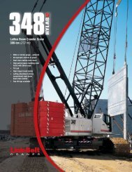
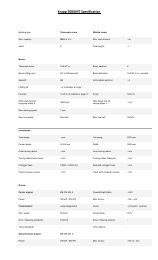
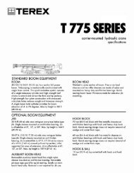
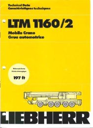
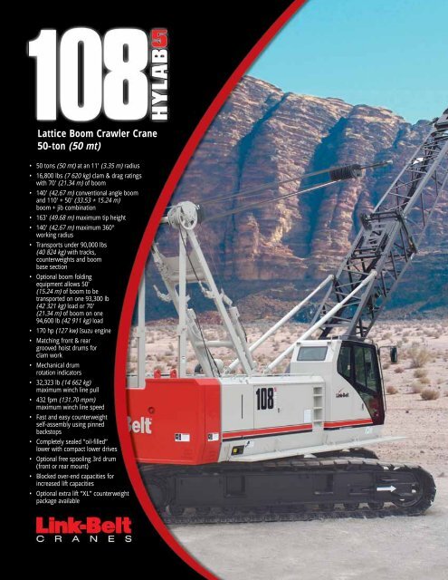
Lattice Boom Crawler Crane50-ton (50 mt)• 50 tons (50 mt) at an 11' (3.35 m) radius• 16,800 lbs (7 620 kg) clam & drag ratingswith 70' (21.34 m) of boom• 140' (42.67 m) conventional angle boomand 110' + 50' (33.53 + 15.24 m)boom + jib combination• 163' (49.68 m) maximum tip height• 140' (42.67 m) maximum 360°working radius• Transports under 90,000 lbs(40 824 kg) with tracks,counterweights and boombase section• Optional boom foldingequipment allows 50'(15.24 m) of boom to betransported on one 93,300 lb(42 321 kg) load or 70'(21.34 m) of boom on one94,600 lb (42 911 kg) load• 170 hp (127 kw) Isuzu engine• Matching front & reargrooved hoist drums forclam work• Mechanical drumrotation indicators• 32,323 lb (14 662 kg)maximum winch line pull• 432 fpm (131.70 mpm)maximum winch line speed• Fast and easy counterweightself-assembly using pinnedbackstops• Completely sealed “oil-filled”lower with compact lower drives• Optional free spooling 3rd drum(front or rear mount)• Blocked over-end capacities forincreased lift capacities• Optional extra lift “XL” counterweightpackage available
42" x 42" (1.06 m x 1.06angle boom extensions inprevious LS-108 42' boomAttachable bridle guide armsto align bridle and base sectfast, easy bridle-to-boom coAll sheaves are sealed andmaintenance-free, givingHYLAB owners outstandingreliability.Lattice Boom Crawler Crane50-ton (50 mt)Whatever your requirements,the 108 H5 has big cranefeatures with small craneaffordability to get yourjob done.• Superb job-site mobility• Fits in places thebig cranes can’t• Superior pile-drivingcapability• Operator-friendly• Transports inone loadPin-on boom hoist bailRear-mount fourthdrum is available withtrue gravity free fallHydraulic counterweight removalcylinders and pinned backstops forfast and easy counterweight removalNon-slip safety strips andquick storage catwalksprovide sure-footedaccess to the crane upperHydraulic cylinder incarbody for effortlessextend/retractWide-opening doors(upper left), two upperaccess ladders withhand-rails (left) andfold-up treadmembersteps prove that accessis the name of the gameon the 108 H5.HYLAB hydraulic swing systemsmoothly rotates on turntablebearing with internal swing teeth.Upper secures into place with atwo-position positive house lock
The standard 40' – 140' (12.19 – 42.67 m) angleboom, the most rugged and robust angle boomavailable, is a top notch performer in dragline,clamshell, pile driving and other severe dutycycle applications.Optional auxiliary tip extension isequipped with two 18.12" (0.46 m)root diameter nylon sheaves, mountedon sealed anti-friction bearings.) in-line pin-connectedterchangeable withextensionsare usedion fornnectionAngle boom designedto accommodate bothlift crane and dutycycle demandsLink-Belt's standard assembly lift hooks and the easyto-usecounterweight removal system are extremelyefficient and simple to use. The lift hooks can alsohandle boom extensions.The auxiliary 9-ton(8.16 mt) capacity,5' (1.5 m) tip extension isdesigned to use insteadof a jib to provide clearancebetween working hoist lines.The boom top sectionfeatures standard pin-onpoints for attachment ofoptions such as a fixed jib,tip extension and adaptersfor universal pile drivingleads with quick reeve ability.The 108 H5 has a dragline/clamshellcapacity of 16,800 lbs (7 620 kg). Thedragline package includes fairleader aswell as bolt-on-front lagging to allowfor 7/8" inhaul.Optional third drum interchangeable with LS-138H IIand LS-208H II third drums. Third drum plumbing isstandard with routing to both front and rear locations.Sealed (oil-filled) track rollers, idlerand drive planetaries and compact hydrostaticdrives add up to outstanding reliabilityand maintenance-free operation.Automatic hydraulictrack tensionSelf-cleaning 36" (0.91 m)track shoes form a widegauge of 11' 2" (3.40 m)when extended, and 8' 9"(2.67 m) when retracted.Lower structure groundclearance is 16.5" (0.42 m).
5495 (supersedes 5462)---0906---N81Technical Data<strong>Spec</strong>ifications & CapacitiesCrawler Crane50 Ton (50 metric ton)CAUTION: This material is supplied for reference useonly. Operator must refer to in---cab Crane RatingManual and Operator’s Manual to determineallowable crane lifting capacities and assembly andoperating procedures.Link-Belt Cranes108 HYLAB 5
5495 (supersedes 5462)---0906---N8108 HYLAB 5 Link-Belt Cranes
5495 (supersedes 5462)---0906---N8Table Of ContentsUpper Structure ............................................................................ 1Frame .................................................................................... 1Engine ................................................................................... 1Hydraulic System .......................................................................... 1Load Hoist Drums ......................................................................... 1Optional Third Hoist Drum .................................................................. 1Optional Fourth Hoist Drum ................................................................. 1Boom Hoist Drum .......................................................................... 2Boom Hoist System ........................................................................ 2Swing System ............................................................................. 2Counterweight ............................................................................ 2Operator’s Cab ............................................................................ 2Rated Capacity Limiter System .............................................................. 2Machinery Cab ............................................................................ 2Catwalks ................................................................................. 2Lower Structure ............................................................................ 2Carbody .................................................................................. 2Side Frames .............................................................................. 2Travel and Steering ........................................................................ 3Attachment and Options .................................................................... 3Conventional Angle Boom .................................................................. 3Tubular Jib ................................................................................ 3Auxiliary Tip Extension ...................................................................... 3Pile Driver Lead Adaptor .................................................................... 3Boom Folding Equipment ................................................................... 3Dimensions ................................................................................ 4Base Crane ............................................................................... 6Side Frames .............................................................................. 6Counterweights ........................................................................... 6Boom .................................................................................... 7Jib ....................................................................................... 8Hook Balls ................................................................................ 9Hook Blocks .............................................................................. 9Fairleader ................................................................................. 9Transport Weights .......................................................................... 10Working Weights ........................................................................... 11Transport Drawings ........................................................................ 11Load Hoist Performance .................................................................... 12Working Areas ............................................................................. 13Attachments ............................................................................... 14Main Boom Make--up ...................................................................... 15Duty Cycle Working Range Diagrams ........................................................ 16Duty Cycle Load Charts .................................................................... 18Main Boom Working Range Diagram ........................................................ 19Link-Belt Cranes108 HYLAB 5
5495 (supersedes 5462)---0906---N8Main Boom Load Charts .................................................................... 20Jib Attachment Make--up ................................................................... 22Jib Attachment Working Range Diagram ..................................................... 23Jib Attachment Load Charts ................................................................. 24108 HYLAB 5 Link-Belt Cranes
5495 (supersedes 5462)---0906---N8Upper StructureFrameAll welded and precision machinedsurfaces.Turntable BearingS Inner race with internal swing gear isbolted to lower frameS Outer race bolted to upper frameEngineEngineFull pressure lubrication, oil filter, aircleaner, hour meter, throttle, and electriccontrol shutdown.Isuzu AH--4HK1XNumber of cylinders 4Bore and strokePiston displacementEngine rpm at fullload speedHi --- idle rpmGross engine hpPeak torqueElectrical systemFuel tank capacityBatteriesApproximate fuelconsumption4.53 in x 4.92 in(115 x 125mm)317 in 3 (5.2L)2,100 rpm2,100 rpm200 hp (148.4kw)507 ft lb (688joule) @1,500 rpm24 volt77 gal (291.5L)2 --- 12 voltgal/hr (L/hr)100% hp 10.42 (39.44)75% hp 8.20 (31.04)50% hp 6.06 (22.94)25% hp 3.03 (11.50)Fuel TankEquipped with fuel sight level gauge,flame arrester, and self---closing cap withlocking eye for padlock.Hydraulic SystemHydraulic PumpsThe pump arrangement is designed toprovide hydraulically powered functionsallowing positive, precise control with independentor simultaneous operation ofall crane functions.S Two variable displacement pumpsoperating at 4,270 psi (300kg/cm 2 )and64 gal/min (296L/min) powers loadhoist drums, boom hoist drum, optionalthirddrum,andtravel.S One fixed displacement gear typepump operating at 3,000 psi(210kg/cm 2 )and29gal/min(111L/min)powers the swing motor and retractcylinders.S One fixed displacement gear typepump operating at 1,200 psi(85kg/cm 2 ) and 6.6 gal/min (25L/min)powers the remote control valves andcounterweight lifting cylinders.Pump Control “Fine Inching” Mode<strong>Spec</strong>ial pump setting, selectable from theoperator’s cab, that allows very slowmovements of load hoist drums, boomhoist drum, and travel for precision work.Hydraulic Reservoir77 gal (291L), equipped with sight levelgauge. Diffusers built in for deaeriation.FiltrationTen micron, full flow, line filter in the controlcircuit. All oil is filtered prior to entering thereservoir.Counterbalance ValvesAll hoist motors are equipped with counterbalancevalves to provide positive loadlowering and prevent accidental loaddrop if the hydraulic pressure is suddenlylost.Load Hoist DrumsEach drum contains a pilot controlled, bi---directional, axial piston motor and a planetarygear reduction unit to provide positivecontrol under all load conditions.S Power up/down and free---fall operationmodesS Automatic brake mode (spring applied,hydraulically released, band typebrake)S Grooved laggingS Drum pawl controlled manuallyS Electronic drum rotation indicatorsS Mounted on anti---friction bearingsS 15.75 in (40.00cm) root diameterS 31.50 in (80.00cm) flange diameterS 16.09 in (40.87cm) width1S Bolt on spiral lagging for 0.88 in(22.22mm) wire rope. Bolts to theflange of front hoist drum. Used fordragline work.The free---fall operation mode is designedto prevent load lowering even if the free---fall switch is accidentally activated.The automatic brake mode meets allOSHA requirements for personnel handling.Drum ClutchesHydraulic two shoe clutch design thatuses a 20 in (50.8cm) diameter x 5 in(12.7cm) wide shoe that expands internallyto provide load control. Swept areais 314 in 2 (2 026cm 2 ).Drum BrakesExternal contracting band design thatuses a 31.5 in (80.01cm) diameter x 4.7 in(11.9cm) wide shoe. Spring applied, hydraulicallyreleased “automatic brakemode” or mechanical foot control.Optional Third Hoist DrumMounts to the front or rear of the upperframe and is used in conjunction with afleeting sheave and 3---sheave idler assemblyto run the wire rope over the boomtop section.S Free---spooling capability for pile drivingapplicationsS 10.63 in (27.0cm) root diameterS 20 in (50.8cm) flange diameterS 13.5 in (34.3cm) widthS Mounted on anti---friction bearingsOptional Fourth Hoist DrumMounts to the rear of the upper frame withgravityfreefallforuseinpiledrivingapplications.S 15.75 in (40.0cm) root diameterS 31.50 in (80.0cm) flange diameterS 10.63 in (27.0cm) widthS Mounted on anti---friction bearingsLink-Belt Cranes108 HYLAB 5
2 5495 (supersedes 5462)---0906---N8Boom Hoist DrumContains a pilot controlled, bi---directional,axial piston motor and a planetary gear reductionunit to provide positive control underall load conditions.S Spring applied, hydraulically released,disc type brake controlled automaticallyS Drum pawl controlled automaticallyS Mounted on anti---friction bearingsS 12.6 in (32.0cm) root diameterS 24.41 in (62.0cm) flange diameterS 9.57 in (24.3cm) widthBoom Hoist SystemDesigned to lift off maximum boom ormaximum boom plus jib unassisted. Operatesup to a maximum boom angle of82˚. Boom hoist limit system limits maximumboom angle operation.S Retractable gantry frameS Pin---on bail frameS 14---part reeving with 5/8 in (15.88mm)wire ropeS Bridle assemblyS Two 1.125 in (28.70mm) pendantsS Tubular boom backstops (telescopictype)S Nylon sheaves contain sealed anti---friction bearingsS Boom speed from 0˚--- 82˚ is 60 secondswith no load.Swing SystemPilot controlled bi---directional axial pistonmotors and planetary gear reduction unitsto provide positive control under all loadconditions.S Spring applied, hydraulically released,360˚ multi --- plate brakeS Free swing mode when lever is in neutralpositionS Two position positive house lockS Audio/Visual swing alarmS Maximum swing speed is 3.4 rpmCounterweightConsists of a two---piece design that canbe easily lowered to the ground using thegantry.S “A” counterweight consists of one,14,000 lb (6 350kg) base slabS Optional “B” counterweight consists ofone, 10,000 lb (4 535kg)S Optional “XL” counterweight packageoffers increased capacities for lift andpiling applications. It consists of one,4,630 lb (2 100kg) upper counterweightand two, 4,300 lb (1 950kg) side framecounterweights. Not for duty cycle application.Not designed to self ---assemble.Operator’s CabFully enclosed modular steel compartmentis independently mounted andpadded to protect against vibration andnoise.S All tinted/tempered safety glassS Sliding entry door and front windowS Door and window locksS Hot water heaterS Air conditionerS Sun visorS Cloth seatS Circulating fanS Windshield wipers and washerS Dry chemical fire extinguisherS Engine instrumentation panel (tachometer,voltmeter, engine oil pressure, enginewater temperature, fuel level, hydraulicoil temperature, hour meter, andservice monitor system)S Mechanical drum rotation indicators forfront and rear hoist drumsS Six way adjustable seatS Hand and foot throttleS Fully adjustable single axis controlsS Swing lever with swing brake and hornlocated on handleS BubbletypelevelS Ergonomic gauge layoutS Controls shut off leverS Right hand control stand is adjustableby electric motor for operator comfort.Rated Capacity LimiterSystemThe rated capacity limiter system is a boomhoist load cell system. This system providesthe operator with useful geometricaldata, to include:S Main Boom LengthS Main Boom AngleS Jib LengthS Jib AngleS Operating ModeS Load RadiusS Boom Tip HeightS Audible AlarmS Pre---Warning LightS Overload LightS Load On HookS Function kick---outs including over loadS Operator settable stops (ramped stops)S Anti---Two Block IndicatorS Boom hoist dead end load cell (nolineriders)Machinery CabHinged doors (two on right side, three onleft side) for machinery access. Equippedwith rooftop access ladder and skid resistantfinish on roof.CatwalksStandard on right and left sides. Catwalksfold up and pin for reduced travel width.Lower StructureCarbodyLower FrameAll welded box construction frame withprecision machined surfaces for turntablebearing and rotating joint.S 7ft9.31in(2.37m) overall widthS 10 ft 9.12 in (3.28m) overall lengthSide FramesSide FramesAll welded, precision machined, steelframes can be hydraulically extended andretracted by a hydraulic cylinder mountedin the lower frame.S 11 ft 2 in (3.40m) extended gaugeS 8ft8.7in(2.66m) retracted gaugeS 17 ft 8 in (5.38m) overall lengthS 36 in (0.91m) wide track shoesS Optional 30 in (0.76m) wide track shoesS Sealed (oil filled) idler and drive planetariesS Compact travel drivesS Hydraulic self adjusting tracks108 HYLAB 5 Link-Belt Cranes
5495 (supersedes 5462)---0906---N83Track RollersS Eight sealed (oil filled) track rollers perside frameS Heat treated, mounted on anti---frictionbearingsTracksHeat treated, self---cleaning, multiplehinged track shoes joined by one---piecefull floating pins; 50 shoes per side frameTake Up IdlersCast steel, heat treated, self---cleaning,mounted on sealed tapered roller bearingsTravel and SteeringTravel and SteeringEach side frame contains a pilot controlled,bi---directional, axial piston motorand a planetary gear reduction unit to providepositive control under all load conditions.S 2---speed travelS Individual control provides smooth,precise maneuverability including fullcounter---rotation.S Spring applied, hydraulically releaseddisc type brake controlled automaticallyS Maximum travel speed is 2.36 mph(3.80km/h) in high speed and 1.3 mph(2.09km/h) in low speed.S Designed to 40% gradeabilityAttachment and OptionsConventional Angle Boom40---140 ft (12.19---42.67m)Basic Boom40 ft (12.19m) two---piece design thatutilizes a 20 ft (6.10m) base section anda20ft(6.10m) open throat top sectionwith in---line connecting pins on 42 in(1.06m) wide and 42 in (1.06m) deepcenters.S Boom foot on 45.2 in (1.15m) centersS 4x4x0.38in(101.6 x 101.6 x 9.5mm)T---1 angle chords for base sectionS 4x4x0.31in(101.6 x 101.6 x 7.87mm)HSLA angle chords for top sectionS Top section includes mounting lugs foralloptionalattachmentsS Bridle guide system located on boombaseS Skywalk platformS Hooks provided on the base section forhandling boomS Two deflector rollers on top sectionS Permanent skid pads mounted on topsection to protect head machineryS Four, 18 in, (0.46m) root diameter steelsheaves mounted on sealed anti---frictionbearingsS Mechanical boom angle indicatorBoom ExtensionsThe following table provides the lengthsavailable and the suggested quantity to obtainmaximum boom in 10 ft (3.05m) increments.Midpoint pendant connections arenot required.S Deflector roller on top of each sectionS Appropriate length pendantsS Maximum tip height of 144 ft (43.90m)BoomExtensionsftmQuantity For MaxBoom10 3.05 220 6.10 130 9.14 2OptionalS Clam head machinery --- Two 18 in(0.46m) root diameter sheavesmounted on sealed anti---friction bearingsand rope roller that bolts to the bottomof boom top.S Drag head machinery --- One 18 in(0.46m) root diameter wide mouth dragsheave mounted on greasable bearings.Two 18 in (0.46m) root diametersteel sheaves mounted on sealed anti---friction bearings. Rope roller bolts tobottom of boom top.Tubular Jib20---50 ft (6.10---15.24m)Basic Tube Jib20 ft (6.10m) two---piece design that utilizesa 10 ft (3.05m) base section and a10 ft (3.05m) top section with in---lineconnecting pins on 30 in (0.76m) wideand 24 in (0.61m) deep centers.S 1.5 in (38.1mm) diameter tubularchordsS One 16.5 in (0.42m) root diameter steelsheave mounted on sealed anti---frictionbearingsS 10 ft (3.05m) jib extensions are availableto provide jib lengths of 30---50 ft(9.14 ---15.24m) in 10 ft (3.05m) incrementsS Jib offset angles at 5˚, 17.5˚, and30˚S The maximum tip height of boom + jibis 163 ft (49.68m).5ft(1.5m) AuxiliaryTip ExtensionDesigned to use in place of jib to provideclearance between working hoist lines.The extension is equipped with two nylon18.12 in (0.46m) root diameter nylonsheaves mounted on sealed anti---frictionbearings. Maximum capacity is 9 Tons(8.16mt).Pile Driver Lead AdaptorDesigned to mount on the boom top sectionto provide a single 3.63 in (92.1mm)pinconnectionforfixedleads.Boom Folding EquipmentConsist of bolt on brackets and pins to allowfolding 50 ft (15.24m) or 70 ft (21.34m)of boom for transport.Link-Belt Cranes108 HYLAB 5
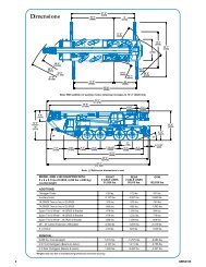
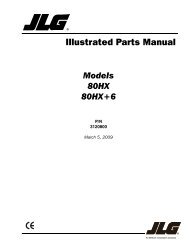
4 5495 (supersedes 5462)---0906---N8DimensionsGeneral Dimensions English MetricBasic Boom 40 ft 12.19mMinimum Load Radius 8.6 ft 2.62mMaximum Boom Angle 82˚ 82˚Track Shoe Width 36 in 0.91m17’ 5.75”(5.32m)8’ 5.88”(2.59m)3’ 9.5”(1.16m)13’ 4”(4.06m)12’ 7.75”(3.85m)17’ 7.88”(5.38m)108 HYLAB 5 Link-Belt Cranes
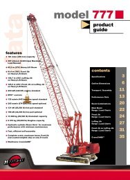
5495 (supersedes 5462)---0906---N85Tailswing Radius w/ XL Counterweight13’ 5.5” (4.10m)Tailswing Radius12’ 9.5” (3.90m)9’ 9.5”(2.98m)12’ 10” (3.91m)11’ 2” (3.40m) Extended8’ 8.75” (2.66m) Retracted10’ 2.25” (3.11m)36” (0.91m)30” (0.91m) Optional16.5” (0.42m)Retracted10’ 10” (3.3m) w/ 30” (0.76m) shoes11’ 8.75” (3.58m) w/ 36” (0.91m) shoesExtended13’ 7.75” (4.16m) w/30” (0.76m) shoes14’ 2” (4.32m) w/36” (0.91m) shoesLink-Belt Cranes108 HYLAB 5
6 5495 (supersedes 5462)---0906---N8Base CraneBase CraneLength 38 ft 6 in (11.73m)Height 11 ft 2.5 in (3.42m)WeightW/Standard 36 in (0.91m) Track Shoes92,809 lb (42 097kg)W/Optional 30 in (0.76m) Track Shoes89,499 lb (40 596kg)HSide FramesWith 36 in (0.91m) TrackShoes Length 17 ft 8 in (5.38m)Width 36 in (0.91m)Height 39.5 in (0.92m)Weight 14,155 lb (6 421kg)WLLWith 30 in (0.76m) TrackShoes Length 17 ft 8 in (5.38m)Width 30 in (0.76m)Height 39.5 in (0.92m)Weight 12,500 lb (5 670kg)HCounterweightsW L“A” CounterweightLength 117.25 in (2.98m)Width 14.5 in (0.37m)Height 51.2 in (1.30m)Weight 14,000 lb (6 350kg)“B” CounterweightLength 117.25 in (2.98m)Width 14 in (0.36m)Height 51.2 in (1.30m)Weight 10,000 lb (4 536kg)WLHH“XL” Side Frame Counterweight Length 110.25 in (2.8m)Width 10 in (0.26m)Height 23.62 in (0.6m)Weight 4,300 lb (1 950kg)“XL” Upper Counterweight WWLLHLength 63.00 in (1.6m)Width 11 in (0.28m)Height 41 in (1.04m)Weight 4,630 lb (2 100kg)HNumber inside black circle “” = # of components108 HYLAB 5 Link-Belt Cranes
5495 (supersedes 5462)---0906---N87Boom42 in (1.06m) x42in(1.06m)Boom ExtensionsWeights Include Pendants and Hardware10 ft (3.05m) ExtensionWeight: 781 lb (354kg)47”(1.19m)47” (1.19m)124”(3.15m)20 ft (6.10m) ExtensionWeight: 1,335 lb (606kg)47”(1.19m)47” (1.19m)244”(6.20m)47” (1.19m)364” (9.25m)30 ft (9.14m) ExtensionWeight: 1,832 lb (831kg)47”(1.19m)L20 ft (6.10m) Boom TopSectionLength 21 ft 10 in (6.65m)Width 50 in (1.27m)Deep 39.75 in (1.01m)Height 43.75 in (1.11m)Weight 2,711 lb (1 230kg)WDHL20 ft (6.10m) Boom BaseSectionLength 20 ft 7 in (6.27m)Width 50 in (1.27m)Deep 39.75 in (1.01m)Height 62.00 in (1.57m)Weight 2,217 lb (1 006kg)WD HNumber inside black circle “” = # of componentsLink-Belt Cranes108 HYLAB 5
8 5495 (supersedes 5462)---0906---N85ft(1.52m) Auxiliary TipExtension*Length 5ft8.75in (1.75m)Width 24 in (0.61m)Height 3 ft 5 in (1.04m)Weight 641 lb (291kg)LWHJib10 ft (3.05m) JibTop Section*Length 11 ft 2 in (3.40m)Width 31.38 in (0.80m)Height 26 in (0.66m)Weight † 383 lb (174kg)† Weight includes pendants and hardware.LWHL10 ft (3.05m) JibBase Section*Length 10 ft 3.25 in (3.13m)Width 31.75 in (0.81m)Height 1 26 in (0.66m)Height 2 47.67 in (1.21m)Weight † 676 lb (307kg)† Weight includes pins, basic frontstay & backstaypendants, and hardware.H1WH210 ft (3.05m) JibExtension*Length 10 ft 2 in (3.10m)Width 31.75 in (0.81m)Height 28.50 in (0.72m)Weight † 195 lb (88kg)† Weights includes pins, pendants, and hardware.LWHNumber inside black circle “” = # of components* --- Optional equipment108 HYLAB 5 Link-Belt Cranes
5495 (supersedes 5462)---0906---N89Hook BallsW8.5 Ton (7.7mt) SwivelHook Ball*HWidth 14.5 in (0.37m)Height 33.8 in (0.86m)Weight 360 lb (163kg)8.5 Ton (7.7mt) Non --- SwivelHook Ball*WWidth 16.5 in (0.42m)Height 35.00 in (0.89m)Weight 360 lb (163kg)HHook Blocks40 Ton (36.3mt)4---Sheave Hook Block*W1W2Width1 14.44 in (0.37m)Width2 17.88 in (0.45m)Width3 15.00 in (0.38m)Height 47.95 in (1.22m)Weight 780 lb (354kg)60 Ton (54.4mt)4---Sheave Hook Block*Width1 20.13 in (0.51m)Width2 20 in (0.51m)Height 50 in (1.27m)Weight 1,110 lb (503kg)HFairleaderFairleader*WLength 62.00 in (1.57m)Width 32.25 in (0.82m)Height 36.25in (0.92m)Weight 1,274 lb (578kg)LHNumber inside black circle “” = # of components* --- Optional equipmentLink-Belt Cranes108 HYLAB 5
10 5495 (supersedes 5462)---0906---N8Transport WeightsBase Crane: Rigid boom backstops, 77 gal (291L) of fuel, catwalks (left and right side), 20 ft (6.10m) base section, bridle/spreader bar, boom hoist reeving, 600 ft (182.88m) oftype ‘DB’ front hoist rope, 500 ft (152.4m) of type ‘RB’ rear hoist rope, and 36 in (0.91m) track shoes.Item DescriptionGross WeightTransport Loadslb (kg) #1 #2Base Crane 68,809 31 212 1Add “A” Counterweight 14,000 6 350 1Add “B” Counterweight 10,000 4 536 1Add “XL” Upper Counterweight 4,630 2 100Add “XL” Side Frame Counterweight (2) 4,300 1 950Add Hydraulic Third Drum without Rope 1,053 478Add 3 Sheave Assembly to the Top Section 390 177Add 20 ft (6.10m) Angle Top Section with 4 Lifting Sheaves 2,711 1 230 1Add 20 ft (6.10m) Angle Top Section with 2 Clam Sheaves 2,680 1 216Add 20 ft (6.10m) Angle Top Section with 1 Drag Sheave and 2 Lifting Sheaves 2,748 1 246Add 10 ft (3.05m) Angle Extension with Pins and Pendants 781 354 2Add 20 ft (6.10m) Angle Extension with Pins and Pendants 1,335 606 1Add 30 ft (9.14m) Angle Extension with Pins and Pendants 1,832 831 2Add Boom Folding Equipment 500 227Add Tagline Winder 650 295Add Fairleader 1,274 578AddPileDriverLeadAdapter 198 90Add 20 ft (6.10m) Tubular Jib with Offset Pendants 1,177 534 1Add 10 ft (3.05m) Tubular Jib Extension 195 88 2Add 5 ft (1.52m) Auxiliary Tip Extension 640 290Add Holding Rope --- 0.75 in (19.05mm) x 145 ft (44.20m) Type ‘DB’ 151 68Add Closing Rope --- 0.75 in (19.05mm) x 180 ft (54.86m) Type ‘DB’ 187 85Add 0.88 in (22.35mm) Front Drum Lagging 327 148Add Inhaul Rope --- 0.88 in (22.35mm) x95ft(28.96m) Type ‘M’ 128 58Add Third Drum Rope --- 0.63 in (16.00mm) x 385 ft (117.35m) Type ‘ZB’ 312 141Add 8.5 Ton (7.7mt) Hook Ball --- Non --- Swivel or Swivel 360 163 1Add 40 Ton (36.3mt) 4 Sheave Hook Block 780 354Add 60 Ton (54.4mt) 4 Sheave Hook Block 1,110 503 1Replace 36 in (0.91m) Track Shoes with 30 in (0.76m) ---3,530 --- 1 601Remove Front Hoist Rope --- 0.75 in (19.05mm) x 600 ft (182.88m) Type ‘DB’ --- 624 --- 283Remove Jib Hoist Rope --- 0.75 in (19.05mm) x 500 ft (152.40m) Type ‘RB’ --- 550 --- 249Remove 20 ft (6.10m) AngleBaseSection ---1,757 --- 797Remove 50 gal (189.3L) of Fuel --- 362 --- 164Approximate Total Shipping Weightlb 92,809 12,309kg 42 097 5 583Notes:Estimated weights vary by +/--- 2%. Numbers in the load columns represent quantities.Estimated transport loads assume the load out consist of 140 ft (39.62m) of angle boom, 50 ft (15.24m) of jib, and “AB” counterweight.Support loads were targeted at 45,000 lb (20 412kg),8ft6in(2.59m) wide, 48 ft (14.63m) long, and 13 ft 6 in (4.11m) high using a drop deck trailer. Thismay vary depending on state laws, empty truck/trailer weights, and style of trailer.108 HYLAB 5 Link-Belt Cranes
5495 (supersedes 5462)---0906---N8Working WeightsOption123Notes:DescriptionBase crane equipped with 40 ft (12.19m) of boom, “A” counterweight, 600 ft (182.88m) fronthoist rope, 500 ft (152.40m) rear hoist rope, 77 gal (291L) of fuel, 60 Ton (54.43mt) hook blockand a 200 lb (90.7kg) operator.Option #1 plus “B” counterweight and 100 ft (30.48m) of boom extensions to obtain 140 ft(39.62m) of main boom.Option #2 plus 50 ft (15.24m) of jib and 8.5 Ton (7.7mt) hookball --- subtract 30 ft (9.14m) ofboom extensions to obtain 110 + 50 ft (33.53 + 15. 24m) of main boom plus jib.36” (914mm) Track Shoes 30” (762mm) Track ShoesGrossWeightlb (kg)86,830(39 385)100,778(45 712)101,068(45 844)GroundBearingPressurepsi (kg/cm 2 )6.85(0.48)7.95(0.56)7.98(0.56)GrossWeightlb (kg)83,384(37 822)97,332(44 149)97,622(44 280)11GroundBearingPressurepsi (kg/cm 2 )Ground bearing pressure is based on the total weight distributed evenly over the track contact area.Total contact area for 30” (0.76m) track shoes is 10,560 in 2 (68 129 cm 2 ). Total contact area for 36” (0.91mm) track shoes is 12,672 in 2 (81 755 cm 2 ).Transport Drawings7.90(0.56)9.22(0.65)9.24(0.65)13’ 2.5”(4.01m)60”(1.52m)25”(0.64m)LOAD #1 --- 92,809 lb (42 097kg)Base crane13’ 2.5”(4.01m)60”(1.52m)25”(0.64m)LOAD #1 (MODIFIED) --- 98,136 lb (44 514kg)Base crane with 70 ft (21.34m) of folded boom10’ 3”(3.12m)12’ 3”(3.73m)58”(1.47m)LOAD #2 --- 12,309 lb (5 583kg)40”(1.06m)20 ft (6.10m) top section, two 10 ft (3.05m) boom extensions, 20 ft (6.10m) boom extension, two 30 ft (9.14m) boom extensions,20 ft (6.10m) jib with offset pendants, two 10 ft (3.05m) jib extensions, 8.5 Ton (7.7mt) hook ball, and 60 Ton (54.4mt) hook blockLink-Belt Cranes108 HYLAB 5
12 5495 (supersedes 5462)---0906---N8Load Hoist PerformanceFrontorRearDrum-- 3/4 in (19mm) Wire RopeRopeMaximum Line Pull No Load Line Speed Full Load Line Speed Pitch Diameter Layer TotalLayer lb kg ft/min m/min ft/min m/min in mm ft m ft m1 32,323 14 662 264 80.5 89 27.1 16.5 419 86 26.3 86 26.32 29,630 13 440 288 87.8 97 29.6 18.0 457 94 28.5 180 54.93 27,350 12 406 312 95.1 105 32.0 19.5 495 101 30.7 281 85.64 25,396 11 520 336 102.4 113 34.5 21.0 533 108 32.9 389 118.55 23,703 10 752 360 109.7 121 37.0 22.5 571 115 35.1 504 153.56 22,222 10 080 384 117.0 129 39.4 24.0 610 122 37.2 626 190.87 20,914 9 487 408 124.3 137 41.9 25.5 648 129 39.4 755 230.28 19,752 8 960 432 131.7 145 44.4 27.0 686 136 41.6 892 271.89 Storage Layer Only 28.5 724 144 43.8 1,035 315.6Front Drum -- 7/8 in (22mm) Wire RopeRopeMaximum Line Pull No Load Line Speed Full Load Line Speed Pitch Diameter Layer TotalLayer lb kg ft/min m/min ft/min m/min in mm ft m ft m1 26,188 11 879 330 100.6 110 33.5 20.4 517 86 26.3 86 26.32 24,116 10 939 358 109.2 119 36.3 22.1 562 94 28.5 180 54.9Boom Hoist Drum -- 5/8 in (16mm) Wire RopeRopeMaximum Line Pull No Load Line Speed Full Load Line Speed Pitch Diameter Layer TotalLayer lb kg ft/min m/min ft/min m/min in mm ft m ft m1 17,080 7 747 194 59.2 172 52.5 13.2 336 48 14.8 48 14.82 15,605 7 078 213 64.8 188 57.4 14.5 368 53 16.1 101 30.83 14,364 6 515 231 70.4 205 62.4 15.7 399 57 17.3 158 48.24 13,306 6 036 249 76.0 221 67.3 17.0 431 61 18.6 219 66.85 12,393 5 622 268 81.6 237 72.3 18.2 463 65 19.9 284 86.66 11,598 5 261 286 87.2 253 77.2 19.5 495 69 21.1 354 107.87 10,898 4 943 304 92.8 270 82.2 20.7 526 74 22.4 427 130.28 10,278 4 662 323 98.4 286 87.2 22.0 558 78 23.7 505 153.9Optional Third Drum -- 5/8 in (16mm) Wire RopeRopeMaximum Line Pull No Load Line Speed Full Load Line Speed Pitch Diameter Layer TotalLayer lb kg ft/min m/min ft/min m/min in mm ft m ft m1 15,041 6 822 157 48 143 43.6 11.3 286 57 17.4 57 17.42 13,537 6 140 175 53 159 48.5 12.5 318 64 19.5 121 36.93 12,307 5 582 192 59 175 43.3 13.8 349 70 21.3 192 58.54 11,282 5 117 210 64 191 58.0 15.0 381 76 23.1 269 82.05 10,414 4 724 228 69 207 63.1 16.3 413 83 25.2 352 107.36 9,671 4 387 245 75 223 68.0 17.5 445 89 27.1 442 134.7Optional Fourth Drum -- 3/4 in (19mm) Wire RopeRopeMaximum Line Pull No Load Line Speed Full Load Line Speed Pitch Diameter Layer TotalLayer lb kg ft/min m/min ft/min m/min in mm ft m ft m1 22,352 10 139 189 57.7 126 38.5 16.5 419 56 17.1 56 17.12 20,489 9 294 207 63.0 138 42.0 18.0 457 61 18.7 117 35.83 18,913 8 579 224 68.2 149 45.5 19.5 495 66 20.2 184 56.04 17,562 7 966 241 73.5 161 49.0 21.0 533 71 21.8 255 77.85 16,391 7 435 258 78.7 172 52.5 22.5 571 77 23.3 332 101.16 15,367 6 970 275 84.0 184 56.0 24.0 610 82 24.9 413 126.07 14,463 6 560 293 89.2 195 59.5 25.5 648 87 26.4 500 152.48 13,659 6 196 310 94.5 207 63.0 27.0 686 92 28.0 592 180.49 12,940 5 870 327 99.7 218 66.5 28.5 724 97 29.6 689 210.010 12,293 5 576 344 105.0 230 70.0 30.0 762 102 31.1 791 241.1108 HYLAB 5 Link-Belt Cranes
5495 (supersedes 5462)---0906---N813DiameterMax. Permissible LoadWire Rope Applicationin mmTypelb kgBoom Hoist 5/8 16 W 11,700 5 307Front Hoist 3/4 19 DB 16,800 7 620Rear Hoist 3/4 19 RB 12,900 5 851Third Drum 5/8 16 ZB 11,080 5 026Clamshell (Holding) 3/4 19 DB 16,800 7 620Clamshell (Closing) 3/4 19 DB 16,800 7 620Dragline (Hoist) 3/4 19 DB 16,800 7 620Dragline (Inhaul) 7/8 22 M 22,740 10 315Working AreasWire Rope Descriptions6 x 26 (6 x 19 Class) --- Extra Improved Plow Steel --- Preformed ---Right Lay --- Alternate Lay --- I.W.R.C.6X26(6X19Class),WarringtonSeale,E.I.P.S., Preformed, RightRegular Lay, I.W.R.C.19 X 19 Rotation Resistant Compacted Strand --- High Strength ---Preformed, Right Regular Lay36 x 7 --- Non-rotating --- Extra Improved Plow Steel --- Right Lay ---Regular Lay6X26(6X19Class),WarringtonSeale,E.I.P.S., Preformed, RightRegular Lay, I.W.R.C.6X26(6X19Class),WarringtonSeale,E.I.P.S., Preformed, RightRegular Lay, I.W.R.C.6X26(6X19Class),WarringtonSeale,E.I.P.S., Preformed, RightRegular Lay, I.W.R.C.6 X 25 (6 X 19 Class), Filler Wire, E.I.P.S., Preformed, I.W.R.C., RightLay, Lang Lay360˚Over SideBoomSee NoteOver Idler EndLongitudinalOf CrawlerCenter OfRotationOver Drive EndIdler SprocketSeeNoteDrive SprocketOverSideNote: These Lines Determine The Limiting Position Of Any Load For Operation Within Working Areas Indicated.Link-Belt Cranes108 HYLAB 5
14 5495 (supersedes 5462)---0906---N8AttachmentsAuxiliary TipExtensionOffset JibMain BoomMain Boom40--140 ft (12.20---42.67m)Main Boom With 5 ft (1.5m)Tip Extension40--110 ft (12.20---33.53m)Main Boom With 20--50 ft(6.10---15.24m) Jib108 HYLAB 5 Link-Belt Cranes
5495 (supersedes 5462)---0906---N8Main Boom Make---up15Boom Lengthft (m)ftmBase Boom Extensions ft (m) Top20(6.14)10(3.05)20(6.14)30(9.10)20(6.14)40 12.20 1 150 15.24 1 1 160 18.29 1 1 170 21.34 1 1 180 24.38 1 1 1 190 27.43 1 1 1 1100 30.48 1 2 1110 33.53 1 1 2 1120 36.58 1 1 2 1130 39.62 1 1 1 2 1140 42.67 1 2 1 2 1Notes:1. Capacities shown are in kips/metric tons (1 kip = 1,000 lb /1 kip = 0.45 metric ton) and are not more than 75% of thetipping loads with the crane standing level on firmsupporting surface. A deduction must be made from thesecapacities for weight of hook block, hook ball, sling,grapple, load weighing device, etc. When using main hookwhile jib or tip extension is attached, reduce capacities byvalues shown in Crane Rating Manual. See Operator’sManual for all limitations when raising or loweringattachment.2. The capacities in the shaded areas are based on structuralstrength. The capacities in the non---shaded areas arebased on stability ratings.3. For recommended reeving, parts of line,wire rope type,and wire rope inspection, see Wire Rope CapacityChart, Operator’s Manual, and Parts Manual.4. Load ratings are based on freely suspended loads andmake no allowances for such factors as the effect of thewind, ground conditions, and operating speeds. Theoperator shall therefore reduce load ratings in order totake these conditions into account. Refer to the CraneRating Manual for Wind Speed Restrictions.5. The least stable rated condition is over the side.6. Booms must be erected and lowered over the end formaximum stability.7. Main boom length must not exceed 140 ft (42.67m).8. Do not operate at radii and boom lengths where theCrane Rating Manual lists no capacity. Do not uselonger booms or jibs than those listed in the CraneRating Manual. Any of the above can cause a tippingcondition, or boom and jib failure.9. These capacities are in compliance with ASME/ANSIB30.5 at date of manufacture.10. These capacities apply only to the crane as originallymanufactured and normally equipped by Link-BeltConstruction Equipment Company.11. These capacities are for “AB” [34,000 lb (15 422kg)] and“AB” + “XL” [38,630 lb (17 522kg) + 8,600 lb (3 900kg)]counterweight configurations as noted.Link-Belt Cranes108 HYLAB 5
16 5495 (supersedes 5462)---0906---N8Duty Cycle Working Range DiagramsDragline Working Range Diagram60.0˚70’BoomLength70’60’60’50’40’50’15.0˚35.5˚35.0˚40’30’Maximum Dumping Height36.9˚20’10’Approximate95’ Inhaul RopeRadius Limit0’--- 10’--- 10’Maximum Digging Depth--- 20’--- 30’--- 20’--- 30’Maximum Digging Depth--- 40’0’10’20’30’ 40’ 50’Maximum Digging Radius--- 40’60’ 70’ 80’ 90’Notes:1. Boom geometry shown is for unloaded condition and crane standing level on firm supporting surface. Boom deflection, subsequentradius, and boom angle change must be accounted for when applying load to hook.2. Maximum and minimum boom angles are equal to the values listed in the capacity chart for each boom length.108 HYLAB 5 Link-Belt Cranes
5495 (supersedes 5462)---0906---N817Clamshell Working Range Diagram82.0˚BoomLength70’60.0˚80’70’60’Closed WorkingBucket Height60’40’50’40.0˚Open WorkingBucket Height50’40’30’Maximum Dumping Height20’10’0’--- 10’--- 10’Maximum Digging Depth--- 20’--- 30’--- 40’--- 20’--- 30’--- 40’Maximum Digging Depth--- 50’0’10’20’30’ 40’ 50’Maximum Digging Radius--- 50’60’ 70’ 80’ 90’Notes:1. Boom geometry shown is for unloaded condition and crane standing level on firm supporting surface. Boom deflection, subsequentradius, and boom angle change must be accounted for when applying load to hook.2. Maximum and minimum boom angles are equal to the values listed in the capacity chart for each boom length.Link-Belt Cranes108 HYLAB 5
18 5495 (supersedes 5462)---0906---N8Duty Cycle Load ChartsDuty Cycle Lift Capacity Chart -- 360_ Rotation -- AB Counterweight -- Side Frames Extended[All capacities are listed in kips (mt)]Boom Length ft (m)LoadRadiusft (m)Dragline40(12.2)Clamshell/MagnetDragline50(15.2)Clamshell/MagnetDragline60(18.3)Clamshell/MagnetDragline70(21.3)Clamshell/Magnet9(2.7)16.8(7.6)16.8(7.6)10(3.1)16.8(7.6)16.8(7.6)16.8(7.6)16.8(7.6)11(3.4)16.8(7.6)16.8(7.6)16.8(7.6)16.8(7.6)12(3.7)16.8(7.6)16.8(7.6)16.8(7.6)16.8(7.6)16.8(7.6)16.8(7.6)13(4.0)16.8(7.6)16.8(7.6)16.8(7.6)16.8(7.6)16.8(7.6)16.8(7.6)16.8(7.6)16.8(7.6)14(4.3)16.8(7.6)16.8(7.6)16.8(7.6)16.8(7.6)16.8(7.6)16.8(7.6)16.8(7.6)16.8(7.6)15(4.6)16.8(7.6)16.8(7.6)16.8(7.6)16.8(7.6)16.8(7.6)16.8(7.6)16.8(7.6)16.8(7.6)16(4.9)16.8(7.6)16.8(7.6)16.8(7.6)16.8(7.6)16.8(7.6)16.8(7.6)16.8(7.6)16.8(7.6)17(5.2)16.8(7.6)16.8(7.6)16.8(7.6)16.8(7.6)16.8(7.6)16.8(7.6)16.8(7.6)16.8(7.6)18(5.5)16.8(7.6)16.8(7.6)16.8(7.6)16.8(7.6)16.8(7.6)16.8(7.6)16.8(7.6)16.8(7.6)19(5.8)16.8(7.6)16.8(7.6)16.8(7.6)16.8(7.6)16.8(7.6)16.8(7.6)16.8(7.6)16.8(7.6)20(6.1)16.8(7.6)16.8(7.6)16.8(7.6)16.8(7.6)16.8(7.6)16.8(7.6)16.8(7.6)16.8(7.6)25(7.6)16.8(7.6)16.8(7.6)16.8(7.6)16.8(7.6)16.8(7.6)16.8(7.6)16.8(7.6)16.8(7.6)30(9.1)16.8(7.6)16.8(7.6)16.8(7.6)16.8(7.6)16.8(7.6)16.8(7.6)16.8(7.6)16.8(7.6)35(10.7)16.8(7.6)16.8(7.6)16.8(7.6)16.8(7.6)16.8(7.6)16.8(7.6)16.8(7.6)16.8(7.6)40(12.2)16.1(7.3)14.4(6.5)15.9(7.2)14.3(6.4)15.7(7.1)14.1(6.4)15.5(7.0)13.9(6.3)50(15.2)11.6(5.2)10.4(4.7)11.4(5.1)10.2(4.6)11.2(5.0)10.0(4.5)60(18.3)8.7(3.9)7.8(3.5)8.5(3.8)7.6(3.4)70(21.3)6.7(3.0)6.0(2.7)This material is supplied for reference use only. Operator must refer to in---cab Crane Rating Manual and Operator’s Manual to determine allowablecrane lifting capacities and assembly and operating procedures.108 HYLAB 5 Link-Belt Cranes
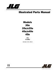
5495 (supersedes 5462)---0906---N8Main Boom Working Range Diagram1940’ To 140’ Open Throat BoomMaximum Boom AngleSeeNote2.160’70˚80˚150’60˚Height In Feet Above Ground140’130’120’110’100’90’80’70’60’50’40’20˚30˚40˚50˚140’130’120’110’100’90’80’70’60’50’40’Main Boom Length30’10˚20’10’0’160’Minimum Boom AngleSeeNote2.150’ 140’ 130’ 120’ 110’ 100’ 90’ 80’ 70’ 60’ 50’ 40’ 30’ 20’ 10’Operating Radius From Centerline Of Rotation In FeetCL OF ROTATIONNotes:1. Boom geometry shown is for unloaded condition and crane standing level on firm supporting surface. Boom deflection, subsequentradius, and boom angle change must be accounted for when applying load to hook.2. Maximum and minimum boom angles are equal to the values listed in the capacity chart for each boom length.Link-Belt Cranes108 HYLAB 5
20 5495 (supersedes 5462)---0906---N8Main Boom Load ChartsMain Boom Lift Capacity Chart -- 360_ Rotation -- AB Counterweight -- Side Frames Extended[All capacities are listed in kips (mt)]LoadRadiusft (m)40(12.2)50(15.2)60(18.3)70(21.3)80(24.4)Boom Length ft (m)90(27.4)100(30.5)110(33.5)120(36.6)130(39.6)140(42.7)9(2.7)100.0(45.3)10(3.1)100.0(45.3)98.4(44.6)11(3.4)100.0(45.3)96.0(43.5)12(3.7)94.2(42.7)93.6(42.4)85.0(38.5)13(4.0)85.9(38.9)85.9(38.9)81.8(37.1)74.0(33.5)14(4.3)75.2(34.1)75.1(34.0)75.0(34.0)72.2(32.7)15(4.6)66.8(30.3)66.7(30.2)66.6(30.2)66.5(30.1)63.8(28.9)16(4.9)60.0(27.2)59.9(27.1)59.8(27.1)59.7(27.0)59.6(27.0)57.4(26.0)17(5.2)54.5(24.7)54.4(24.6)54.2(24.5)54.1(24.5)54.0(24.5)53.8(24.4)51.7(23.4)18(5.5)49.8(22.5)49.7(22.5)49.5(22.4)49.4(22.4)49.3(22.3)49.1(22.2)49.0(22.2)19(5.8)45.8(20.7)45.7(20.7)45.6(20.6)45.4(20.6)45.3(20.5)45.1(20.4)45.0(20.4)44.8(20.3)20(6.1)42.4(19.2)42.3(19.1)42.1(19.1)42.0(19.0)41.9(19.0)41.7(18.9)41.5(18.8)41.4(18.7)41.1(18.6)25(7.6)30.7(13.9)30.6(13.8)30.4(13.7)30.2(13.7)30.1(13.6)29.9(13.5)29.7(13.4)29.5(13.3)29.3(13.3)29.1(13.2)29.0(13.1)30(9.1)23.8(10.8)23.7(10.7)23.5(10.6)23.3(10.5)23.1(10.4)22.9(10.3)22.8(10.3)22.6(10.2)22.4(10.1)22.2(10.0)22.0(9.9)35(10.7)19.3(8.7)19.1(8.6)18.9(8.5)18.8(8.5)18.6(8.4)18.4(8.3)18.2(8.2)18.0(8.1)17.8(8.0)17.6(7.9)17.4(7.9)40(12.2)16.1(7.3)15.9(7.2)15.7(7.1)15.5(7.0)15.3(6.9)15.1(6.8)14.9(6.7)14.7(6.6)14.5(6.5)14.3(6.4)14.1(6.4)50(15.2)11.6(5.2)11.4(5.1)11.2(5.0)11.1(5.0)10.8(4.9)10.6(4.8)10.4(4.7)10.2(4.6)10.0(4.5)9.8(4.4)60(18.3)8.7(3.9)8.5(3.8)8.3(3.7)8.1(3.6)7.9(3.5)7.7(3.5)7.5(3.4)7.3(3.3)7.0(3.1)70(21.3)6.7(3.0)6.5(2.9)6.3(2.8)6.1(2.7)5.8(2.6)5.6(2.5)5.4(2.4)5.2(2.3)80(24.4)5.1(2.3)4.9(2.2)4.7(2.1)4.5(2.0)4.2(1.9)4.0(1.8)3.8(1.7)90(27.4)3.8(1.7)3.6(1.6)3.4(1.5)3.2(1.4)3.0(1.3)2.7(1.2)100(30.5)2.8(1.2)2.6(1.1)2.4(1.0)2.1(0.9)1.9(0.8)110(33.5)1.9(0.8)1.7(0.7)This material is supplied for reference use only. Operator must refer to in---cab Crane Rating Manual and Operator’s Manual to determine allowablecrane lifting capacities and assembly and operating procedures.108 HYLAB 5 Link-Belt Cranes
5495 (supersedes 5462)---0906---N821Main Boom Lift Capacity Chart -- 360_ Rotation -- AB+XL Counterweight -- Side Frames Extended[All capacities are listed in kips (mt)]LoadRadiusft (m)40(12.2)50(15.2)60(18.3)70(21.3)80(24.4)Boom Length ft (m)90(27.4)100(30.5)110(33.5)120(36.6)130(39.6)140(42.7)9(2.7)110.0(49.9)10(3.1)110.0(49.9)11(3.4)103.8(47.1)96.0(43.6)12(3.7)95.1(43.1)93.6(42.5)85.0(38.6)13(4.0)87.8(39.8)87.8(39.8)81.8(37.1)74.0(33.6)14(4.3)81.5(37.0)81.5(37.0)79.7(36.2)72.2(32.8)15(4.6)76.1(34.5)76.1(34.5)76.1(34.5)70.8(32.1)63.8(28.9)16(4.9)69.9(31.7)69.8(31.7)69.7(31.6)69.1(31.4)62.2(28.2)57.4(26.0)17(5.2)63.5(28.8)63.4(28.8)63.2(28.7)63.1(28.6)61.4(27.9)56.3(25.5)51.7(23.5)18(5.5)58.1(26.4)58.0(26.3)57.8(26.2)57.7(26.2)57.6(26.1)55.2(25.0)51.0(23.1)19(5.8)53.5(24.3)53.4(24.2)53.2(24.1)53.1(24.1)52.9(24.0)52.8(24.0)48.8(22.1)45.1(20.5)20(6.1)49.6(22.5)49.4(22.4)49.3(22.4)49.1(22.3)49.0(22.2)48.8(22.1)48.2(21.9)44.5(20.2)41.1(18.6)25(7.6)36.0(16.3)35.9(16.3)35.7(16.2)35.5(16.1)35.3(16.0)35.2(16.0)35.0(15.9)34.8(15.8)34.6(15.7)34.4(15.6)31.4(14.2)30(9.1)28.0(12.7)27.9(12.7)27.7(12.6)27.5(12.5)27.3(12.4)27.1(12.3)26.9(12.2)26.7(12.1)26.5(12.0)26.3(11.9)26.1(11.8)35(10.7)22.8(10.3)22.6(10.3)22.4(10.2)22.2(10.1)22.0(10.0)21.8(9.9)21.6(9.8)21.4(9.7)21.2(9.6)21.0(9.5)20.8(9.4)40(12.2)19.0(8.6)18.9(8.6)18.7(8.5)18.5(8.4)18.3(8.3)18.1(8.2)17.9(8.1)17.7(8.0)17.5(7.9)17.3(7.8)17.1(7.8)50(15.2)13.9(6.3)13.7(6.2)13.5(6.1)13.3(6.0)13.1(5.9)12.9(5.9)12.7(5.8)12.5(5.7)12.3(5.6)12.1(5.5)60(18.3)10.6(4.8)10.4(4.7)10.2(4.6)10.0(4.5)9.8(4.4)9.6(4.4)9.4(4.3)9.1(4.1)8.9(4.0)70(21.3)8.2(3.7)8.1(3.7)7.8(3.5)7.6(3.4)7.4(3.4)7.2(3.3)7.0(3.2)6.7(3.0)80(24.4)6.5(2.9)6.3(2.9)6.0(2.7)5.8(2.6)5.6(2.5)5.4(2.5)5.2(2.4)90(27.4)5.0(2.3)4.8(2.2)4.6(2.1)4.4(2.0)4.2(1.9)3.9(1.8)100(30.5)3.9(1.8)3.7(1.7)3.4(1.5)3.2(1.5)3.0(1.4)110(33.5)2.9(1.3)2.7(1.2)2.4(1.1)2.2(1.0)120(36.65)2.0(0.9)1.8(0.8)1.6(0.7)This material is supplied for reference use only. Operator must refer to in---cab Crane Rating Manual and Operator’s Manual to determine allowablecrane lifting capacities and assembly and operating procedures.Link-Belt Cranes108 HYLAB 5
22 5495 (supersedes 5462)---0906---N8Jib Attachment Make---upJibLengthft (m)Base Jib Extensions Top10 ft(3.05m)10 ft (3.05m)10 ft(3.05m)20 (6.10) 1 130 (9.15) 1 1 140 (12.19) 1 2 150 (15.24) 1 3 1Notes:1. Capacities shown are in kips/metric tons (1 kip = 1,000 lb /1 kip = 0.45 metric ton) and are not more than 75% of thetipping loads with the crane standing level on a firmsupporting surface.2. A deduction must be made from these capacities for theweight of the main boom hook block or hook ball, jib hookblock or hook ball, slings, grapples, load weighing devices,etc. When using main hook while jib is attached, reducecapacities by values shown in Crane Rating Manual. SeeOperator’s Manual for all limitations when raising orlowering attachment.3. The capacities in the shaded areas are based on structuralstrength. The capacities in the non---shaded areas arebased on stability ratings.4. Load ratings are based on freely suspended loads andmake no allowances for such factors as the effect of thewind, ground conditions, and operating speeds. Theoperator shall therefore reduce load ratings in order totake these conditions into account. Refer to the CraneRating Manual for Wind Speed Restrictions.5. These capacities are for “AB” [34,000 lb (15 422kg)] and“AB” + “XL” [38,630 lb (17 522kg) + 8,600 lb (3 900kg)].6. These capacities are for 360˚ working areas.7. These capacities are for 20---50 ft (6.10---15.24m) jiblengths only.8. The jib cannot be used on boom lengths over 110 ft(33.52m).9. The least stable rated condition is over the side.10. These capacities are in compliance with ASME/ANSIB30.5 at date of manufacture.11. These capacities apply only to the crane as originallymanufactured and normally equipped by Link-BeltConstruction Equipment Company.108 HYLAB 5 Link-Belt Cranes
5495 (supersedes 5462)---0906---N8Jib Attachment Working RangeDiagram2340’ To 110’ Main Boom With 20’ To 50’ JibMaximum Boom AngleSeeNote2.170’30_ 17.5_5_80°50’160’150’60°70°40’30’Jib Length140’130’50°20’120’110’100’40°110’100’Height In Feet Above Ground90’80’70’60’50’40’20°30°90’80’70’60’50’40’Main Boom Length30’Minimum Boom AngleSeeNote2.20’10’0’160’ 150’ 140’ 130’ 120’ 110’ 100’ 90’ 80’ 70’ 60’ 50’ 40’ 30’ 20’ 10’Operating Radius From Centerline Of Rotation In FeetNotes:CL OF ROTATION1. Boom geometry shown is for unloaded condition and crane standing level on firm supporting surface. Boom deflection, subsequentradius, and boom angle change must be accounted for when applying load to hook.2. Maximum and minimum boom angles are equal to the values listed in the capacity chart for each boom length.Link-Belt Cranes108 HYLAB 5
24 5495 (supersedes 5462)---0906---N8Jib Attachment Load Charts40 ft (12.2m) Main Boom Length --- 360_ Rotation --- AB or AB+XL Counterweight[All capacities are listed in kips (mt)]LoadRadiusft (m)20(6.1)5˚ Offset 17.5˚ Offset 30˚ OffsetJib Length ft (m)30(9.1)40(12.2)50(15.2)LoadRadiusft (m)20(6.1)Jib Length ft (m)30(9.1)40(12.2)50(15.2)LoadRadiusft (m)20(6.1)Jib Length ft (m)30(9.1)40(12.2)50(15.2)16 20.0 16 16(4.9) (9.0) (4.9) (4.9)17 20.0 17 17(5.2) (9.0) (5.2) (5.2)18 20.0 20.0 18 18(5.5) (9.0) (9.0) (5.5) (5.5)19 20.0 20.0 19 19(5.8) (9.0) (9.0) (5.8) (5.8)20 20.0 20.0 20 20.0 20(6.1) (9.0) (9.0) (6.1) (9.0) (6.1)25 20.0 20.0 20.0 19.0 25 20.0 19.5 25 14.4(7.6) (9.0) (9.0) (9.0) (8.6) (7.6) (9.0) (8.8) (7.6) (6.5)30 20.0 20.0 20.0 17.9 30 19.8 17.2 15.5 30 13.1 11.1(9.1) (9.0) (9.0) (9.0) (8.1) (9.1) (8.9) (7.8) (7.0) (9.1) (5.9) (5.0)35 19.8 20.0 18.3 16.0 35 17.7 15.3 13.8 12.7 35 12.1 10.2(10.7) (8.9) (9.0) (8.3) (7.2) (10.7) (8.0) (6.9) (6.2) (5.7) (10.7) (5.4) (4.6)40 16.5 16.7 16.8 15.0 40 16.0 13.8 12.5 11.4 40 11.3 9.5 8.3(12.2) (7.4) (7.5) (7.6) (6.8) (12.2) (7.2) (6.2) (5.6) (5.1) (12.2) (5.1) (4.3) (3.7)50 12.2 12.4 12.5 12.4 50 12.3 11.7 10.4 9.5 50 8.3 7.2 6.4(15.2) (5.5) (5.6) (5.6) (5.6) (15.2) (5.5) (5.3) (4.7) (4.3) (15.2) (3.7) (3.2) (2.9)60 9.6 9.7 9.8 60 9.7 9.0 8.2 60 6.4 5.6(18.3) (4.3) (4.4) (4.4) (18.3) (4.4) (4.0) (3.7) (18.3) (2.9) (2.5)70 7.8 7.9 70 8.0 7.2 70 5.0(21.3) (3.5) (3.5) (21.3) (3.6) (3.2) (21.3) (2.2)80 6.5 80 6.4(24.4) (2.9) (24.4) (2.9)This material is supplied for reference use only. Operator must refer to in---cab Crane Rating Manual and Operator’s Manual to determine allowablecrane lifting capacities and assembly and operating procedures.108 HYLAB 5 Link-Belt Cranes
5495 (supersedes 5462)---0906---N82550 ft (15.2m) Main Boom Length --- 360_ Rotation --- AB or AB+XL Counterweight[All capacities are listed in kips (mt)]5˚ Offset 17.5˚ Offset 30˚ OffsetLoadRadiusft (m)20(6.1)Jib Length ft (m)30(9.1)40(12.2)50(15.2)LoadRadiusft (m)20(6.1)Jib Length ft (m)30(9.1)40(12.2)50(15.2)LoadRadiusft (m)20(6.1)Jib Length ft (m)30(9.1)40(12.2)50(15.2)18 20.0 18 18(5.5) (9.0) (5.5) (5.5)19 20.0 19 19(5.8) (9.0) (5.8) (5.8)20 20.0 20.0 20 20(6.1) (9.0) (9.0) (6.1) (6.1)25 20.0 20.0 20.0 19.2 25 20.0 25 14.9(7.6) (9.0) (9.0) (9.0) (8.7) (7.6) (9.0) (7.6) (6.7)30 20.0 20.0 19.7 17.4 30 20.0 18.1 30 13.7(9.1) (9.0) (9.0) (8.9) (7.9) (9.1) (9.0) (8.2) (9.1) (6.2)35 19.5 19.7 17.5 16.0 35 19.2 16.3 14.5 13.1 35 12.7 10.6(10.7) (8.8) (8.9) (7.9) (7.2) (10.7) (8.7) (7.4) (6.5) (5.9) (10.7) (5.7) (4.8)40 16.3 16.5 16.3 14.4 40 16.5 14.8 13.2 11.9 40 11.9 9.9 8.5(12.2) (7.4) (7.4) (7.4) (6.5) (12.2) (7.4) (6.7) (5.9) (5.4) (12.2) (5.4) (4.5) (3.8)50 11.9 12.1 12.3 11.9 50 12.1 12.4 11.1 10.1 50 10.7 8.7 7.5 6.6(15.2) (5.4) (5.4) (5.5) (5.4) (15.2) (5.4) (5.6) (5.0) (4.5) (15.2) (4.8) (3.9) (3.4) (3.0)60 9.2 9.4 9.5 9.6 60 9.3 9.5 9.7 8.7 60 7.9 6.7 5.8(18.3) (4.1) (4.2) (4.3) (4.3) (18.3) (4.2) (4.3) (4.4) (3.9) (18.3) (3.5) (3.0) (2.6)70 7.5 7.6 7.7 70 7.6 7.8 7.7 70 6.1 5.3(21.3) (3.4) (3.4) (3.5) (21.3) (3.4) (3.5) (3.5) (21.3) (2.7) (2.4)80 6.2 6.3 80 6.3 6.4 80 4.8(24.4) (2.8) (2.8) (24.4) (2.8) (2.9) (24.4) (2.1)90 5.2 90 5.3(27.4) (2.3) (27.4) (2.4)This material is supplied for reference use only. Operator must refer to in---cab Crane Rating Manual and Operator’s Manual to determine allowablecrane lifting capacities and assembly and operating procedures.Link-Belt Cranes108 HYLAB 5
26 5495 (supersedes 5462)---0906---N860 ft (18.3m) Main Boom Length --- 360_ Rotation --- AB or AB+XL Counterweight[All capacities are listed in kips (mt)]5˚ Offset 17.5˚ Offset 30˚ OffsetLoadRadiusft (m)20(6.1)Jib Length ft (m)30(9.1)40(12.2)50(15.2)LoadRadiusft (m)20(6.1)Jib Length ft (m)30(9.1)40(12.2)50(15.2)LoadRadiusft (m)20(6.1)Jib Length ft (m)30(9.1)40(12.2)50(15.2)19 20.0 19 19(5.8) (9.0) (5.8) (5.8)20 20.0 20 20(6.1) (9.0) (6.1) (6.1)25 20.0 20.0 20.0 25 20.0 25(7.6) (9.0) (9.0) (9.0) (7.6) (9.0) (7.6)30 20.0 20.0 19.4 17.0 30 20.0 18.6 30 14.2(9.1) (9.0) (9.0) (8.8) (7.7) (9.1) (9.0) (8.4) (9.1) (6.4)35 19.3 19.5 17.2 15.8 35 19.6 17.0 14.8 35 13.2 10.9(10.7) (8.7) (8.8) (7.8) (7.1) (10.7) (8.9) (7.7) (6.7) (10.7) (5.9) (4.9)40 16.1 16.3 16.2 14.2 40 16.3 15.7 13.6 11.8 40 12.5 10.2 8.8(12.2) (7.3) (7.4) (7.3) (6.4) (12.2) (7.4) (7.1) (6.1) (5.3) (12.2) (5.6) (4.6) (4.0)50 11.7 11.9 12.0 11.7 50 11.9 12.2 11.6 10.1 50 11.2 9.1 7.7 6.8(15.2) (5.3) (5.4) (5.4) (5.3) (15.2) (5.4) (5.5) (5.2) (4.5) (15.2) (5.0) (4.1) (3.5) (3.0)60 8.9 9.1 9.2 9.3 60 9.1 9.3 9.5 8.8 60 9.2 8.3 7.0 6.0(18.3) (4.0) (4.1) (4.1) (4.2) (18.3) (4.1) (4.2) (4.3) (4.0) (18.3) (4.1) (3.7) (3.1) (2.7)70 7.0 7.2 7.3 7.4 70 7.1 7.4 7.5 7.7 70 7.5 6.4 5.5(21.3) (3.1) (3.2) (3.3) (3.3) (21.3) (3.2) (3.3) (3.4) (3.5) (21.3) (3.4) (2.9) (2.5)80 5.8 5.9 6.0 80 5.9 6.1 6.2 80 5.9 5.0(24.4) (2.6) (2.6) (2.7) (24.4) (2.6) (2.7) (2.8) (24.4) (2.6) (2.2)90 4.8 4.9 90 5.1 90 4.7(27.4) (2.1) (2.2) (27.4) (2.3) (27.4) (2.1)100 4.1 100 100(30.5) (1.8) (30.5) (30.5)This material is supplied for reference use only. Operator must refer to in---cab Crane Rating Manual and Operator’s Manual to determine allowablecrane lifting capacities and assembly and operating procedures.108 HYLAB 5 Link-Belt Cranes
5495 (supersedes 5462)---0906---N82770 ft (21.3m) Main Boom Length --- 360_ Rotation --- AB or AB+XL Counterweight[All capacities are listed in kips (mt)]5˚ Offset 17.5˚ Offset 30˚ OffsetLoadRadiusft (m)20(6.1)Jib Length ft (m)30(9.1)40(12.2)50(15.2)LoadRadiusft (m)20(6.1)Jib Length ft (m)30(9.1)40(12.2)50(15.2)LoadRadiusft (m)20(6.1)Jib Length ft (m)30(9.1)40(12.2)50(15.2)25 20.0 20.0 25 20.0 25(7.6) (9.0) (9.0) (7.6) (9.0) (7.6)30 20.0 20.0 19.3 16.8 30 20.0 18.2 30 14.5(9.1) (9.0) (9.0) (8.7) (7.6) (9.1) (9.0) (8.2) (9.1) (6.5)35 19.1 19.3 17.2 15.8 35 19.4 16.6 14.5 35 13.7 11.2(10.7) (8.6) (8.7) (7.8) (7.1) (10.7) (8.8) (7.5) (6.5) (10.7) (6.2) (5.0)40 15.9 16.1 16.2 14.2 40 16.2 16.1 13.3 11.5 40 12.9 10.5(12.2) (7.2) (7.3) (7.3) (6.4) (12.2) (7.3) (7.3) (6.0) (5.2) (12.2) (5.8) (4.7)50 11.5 11.7 11.8 11.7 50 11.7 12.0 11.5 9.8 50 11.7 9.4 8.0 6.9(15.2) (5.2) (5.3) (5.3) (5.3) (15.2) (5.3) (5.4) (5.2) (4.4) (15.2) (5.3) (4.2) (3.6) (3.1)60 8.7 8.9 9.0 9.1 60 8.9 9.1 9.3 8.6 60 9.0 8.6 7.2 6.2(18.3) (3.9) (4.0) (4.0) (4.1) (18.3) (4.0) (4.1) (4.2) (3.9) (18.3) (4.0) (3.9) (3.2) (2.8)70 6.8 7.0 7.1 7.2 70 6.9 7.2 7.4 7.5 70 7.3 6.6 5.7(21.3) (3.0) (3.1) (3.2) (3.2) (21.3) (3.1) (3.2) (3.3) (3.4) (21.3) (3.3) (3.0) (2.5)80 5.4 5.6 5.7 5.8 80 5.7 5.9 6.0 80 6.1 5.2(24.4) (2.4) (2.5) (2.5) (2.6) (24.4) (2.5) (2.6) (2.7) (24.4) (2.7) (2.3)90 4.5 4.6 4.7 90 4.8 4.9 90 4.9(27.4) (2.0) (2.0) (2.1) (27.4) (2.1) (2.2) (27.4) (2.2)100 3.8 3.8 100 4.0 100(30.5) (1.7) (1.7) (30.5) (1.8) (30.5)110 3.1 110 110(33.5) (1.4) (33.5) (33.5)This material is supplied for reference use only. Operator must refer to in---cab Crane Rating Manual and Operator’s Manual to determine allowablecrane lifting capacities and assembly and operating procedures.Link-Belt Cranes108 HYLAB 5
28 5495 (supersedes 5462)---0906---N880 ft (24.4m) Main Boom Length --- 360_ Rotation --- AB or AB+XL Counterweight[All capacities are listed in kips (mt)]5˚ Offset 17.5˚ Offset 30˚ OffsetLoadRadiusft (m)20(6.1)Jib Length ft (m)30(9.1)40(12.2)50(15.2)LoadRadiusft (m)20(6.1)Jib Length ft (m)30(9.1)40(12.2)50(15.2)LoadRadiusft (m)20(6.1)Jib Length ft (m)30(9.1)40(12.2)50(15.2)25 20.0 20.0 25 25(7.6) (9.0) (9.0) (7.6) (7.6)30 20.0 20.0 19.3 30 20.0 30 14.9(9.1) (9.0) (9.0) (8.7) (9.1) (9.0) (9.1) (6.7)35 18.9 19.1 17.2 15.8 35 19.3 16.7 35 14.0(10.7) (8.5) (8.6) (7.8) (7.1) (10.7) (8.7) (7.5) (10.7) (6.3)40 15.6 15.8 16.0 14.2 40 16.0 16.0 13.2 11.3 40 13.3 10.8(12.2) (7.0) (7.1) (7.2) (6.4) (12.2) (7.2) (7.2) (5.9) (5.1) (12.2) (6.0) (4.9)50 11.3 11.4 11.6 11.7 50 11.5 11.8 11.4 9.7 50 11.7 9.7 8.2 7.1(15.2) (5.1) (5.1) (5.2) (5.3) (15.2) (5.2) (5.3) (5.1) (4.4) (15.2) (5.3) (4.4) (3.7) (3.2)60 8.5 8.7 8.8 8.9 60 8.7 8.9 9.2 8.5 60 8.8 8.9 7.4 6.4(18.3) (3.8) (3.9) (4.0) (4.0) (18.3) (3.9) (4.0) (4.1) (3.8) (18.3) (4.0) (4.0) (3.3) (2.9)70 6.6 6.7 6.9 6.9 70 6.7 7.0 7.2 7.3 70 6.8 7.1 6.9 5.8(21.3) (3.0) (3.0) (3.1) (3.1) (21.3) (3.0) (3.1) (3.2) (3.3) (21.3) (3.0) (3.2) (3.1) (2.6)80 5.2 5.3 5.5 5.5 80 5.3 5.5 5.7 5.8 80 5.6 5.9 5.4(24.4) (2.3) (2.4) (2.5) (2.5) (24.4) (2.4) (2.5) (2.5) (2.6) (24.4) (2.5) (2.6) (2.4)90 4.1 4.3 4.4 4.5 90 4.4 4.6 4.7 90 4.7 4.9(27.4) (1.8) (1.9) (2.0) (2.0) (27.4) (2.0) (2.0) (2.1) (27.4) (2.1) (2.2)100 3.4 3.5 3.6 100 3.7 3.8 100 4.0(30.5) (1.5) (1.5) (1.6) (30.5) (1.6) (1.7) (30.5) (1.8)110 2.8 2.9 110 3.1 110(33.5) (1.2) (1.3) (33.5) (1.4) (33.5)120 2.3 120 120(36.6) (1.0) (36.6) (36.6)This material is supplied for reference use only. Operator must refer to in---cab Crane Rating Manual and Operator’s Manual to determine allowablecrane lifting capacities and assembly and operating procedures.108 HYLAB 5 Link-Belt Cranes
5495 (supersedes 5462)---0906---N82990 ft (27.4m) Main Boom Length --- 360_ Rotation --- AB or AB+XL Counterweight[All capacities are listed in kips (mt)]5˚ Offset 17.5˚ Offset 30˚ OffsetLoadRadiusft (m)20(6.1)Jib Length ft (m)30(9.1)40(12.2)50(15.2)LoadRadiusft (m)20(6.1)Jib Length ft (m)30(9.1)40(12.2)50(15.2)LoadRadiusft (m)20(6.1)Jib Length ft (m)30(9.1)40(12.2)50(15.2)25 20.0 25 25(7.6) (9.0) (7.6) (7.6)30 20.0 20.0 19.3 30 20.0 30(9.1) (9.0) (9.0) (8.7) (9.1) (9.0) (9.1)35 18.6 18.8 17.3 15.9 35 19.1 16.7 35 14.3(10.7) (8.4) (8.5) (7.8) (7.2) (10.7) (8.6) (7.5) (10.7) (6.4)40 15.4 15.6 15.8 14.3 40 15.8 15.9 13.1 40 13.6 11.0(12.2) (6.9) (7.0) (7.1) (6.4) (12.2) (7.1) (7.2) (5.9) (12.2) (6.1) (4.9)50 11.0 11.2 11.3 11.4 50 11.3 11.6 11.3 9.6 50 11.5 10.0 8.3(15.2) (4.9) (5.0) (5.1) (5.1) (15.2) (5.1) (5.2) (5.1) (4.3) (15.2) (5.2) (4.5) (3.7)60 8.3 8.4 8.6 8.6 60 8.5 8.7 9.0 8.5 60 8.6 9.0 7.6 6.5(18.3) (3.7) (3.8) (3.9) (3.9) (18.3) (3.8) (3.9) (4.0) (3.8) (18.3) (3.9) (4.0) (3.4) (2.9)70 6.4 6.5 6.6 6.7 70 6.5 6.8 7.0 7.1 70 6.6 7.0 7.1 6.0(21.3) (2.9) (2.9) (3.0) (3.0) (21.3) (2.9) (3.0) (3.1) (3.2) (21.3) (3.0) (3.1) (3.2) (2.7)80 5.0 5.1 5.2 5.3 80 5.1 5.3 5.5 5.6 80 5.2 5.5 5.7 5.6(24.4) (2.2) (2.3) (2.3) (2.4) (24.4) (2.3) (2.4) (2.5) (2.5) (24.4) (2.3) (2.5) (2.5) (2.5)90 3.9 4.0 4.1 4.2 90 4.0 4.2 4.3 4.5 90 4.3 4.5 4.7(27.4) (1.7) (1.8) (1.8) (1.9) (27.4) (1.8) (1.9) (1.9) (2.0) (27.4) (1.9) (2.0) (2.1)100 3.0 3.2 3.3 3.4 100 3.3 3.5 3.6 100 3.6 3.8(30.5) (1.3) (1.4) (1.5) (1.5) (30.5) (1.5) (1.5) (1.6) (30.5) (1.6) (1.7)110 2.5 2.6 2.7 110 2.7 2.8 110 3.0(33.5) (1.1) (1.1) (1.2) (33.5) (1.2) (1.2) (33.5) (1.3)120 2.0 2.1 120 2.2 120(36.6) (0.9) (0.9) (36.6) (1.0) (36.6)130 1.6 130 130(39.6) (0.7) (39.6) (39.6)This material is supplied for reference use only. Operator must refer to in---cab Crane Rating Manual and Operator’s Manual to determine allowablecrane lifting capacities and assembly and operating procedures.Link-Belt Cranes108 HYLAB 5
30 5495 (supersedes 5462)---0906---N8100 ft (30.5m) Main Boom Length --- 360_ Rotation --- AB or AB+XL Counterweight[All capacities are listed in kips (mt)]5˚ Offset 17.5˚ Offset 30˚ OffsetLoadRadiusft (m)20(6.1)Jib Length ft (m)30(9.1)40(12.2)50(15.2)LoadRadiusft (m)20(6.1)Jib Length ft (m)30(9.1)40(12.2)50(15.2)LoadRadiusft (m)20(6.1)Jib Length ft (m)30(9.1)40(12.2)50(15.2)30 20.0 20.0 30 20.0 30(9.1) (9.0) (9.0) (9.1) (9.0) (9.1)35 18.4 18.6 17.4 15.9 35 18.9 16.7 35 14.6(10.7) (8.3) (8.4) (7.9) (7.2) (10.7) (8.5) (7.5) (10.7) (6.6)40 15.2 15.4 15.6 14.4 40 15.6 15.9 13.0 40 13.9 11.2(12.2) (6.9) (6.9) (7.0) (6.5) (12.2) (7.0) (7.2) (5.9) (12.2) (6.3) (5.0)50 10.8 11.0 11.1 11.2 50 11.1 11.4 11.3 9.5 50 11.4 10.2 8.5(15.2) (4.9) (4.9) (5.0) (5.0) (15.2) (5.0) (5.1) (5.1) (4.3) (15.2) (5.1) (4.6) (3.8)60 8.0 8.2 8.3 8.4 60 8.3 8.5 8.8 8.4 60 8.5 8.8 7.8 6.6(18.3) (3.6) (3.7) (3.7) (3.8) (18.3) (3.7) (3.8) (4.0) (3.8) (18.3) (3.8) (4.0) (3.5) (3.0)70 6.1 6.3 6.4 6.5 70 6.3 6.5 6.8 6.9 70 6.4 6.8 7.1 6.1(21.3) (2.7) (2.8) (2.9) (2.9) (21.3) (2.8) (2.9) (3.0) (3.1) (21.3) (2.9) (3.0) (3.2) (2.7)80 4.7 4.9 5.0 5.1 80 4.9 5.1 5.3 5.4 80 5.0 5.3 5.5 5.7(24.4) (2.1) (2.2) (2.2) (2.3) (24.4) (2.2) (2.3) (2.4) (2.4) (24.4) (2.2) (2.4) (2.5) (2.5)90 3.6 3.8 3.9 4.0 90 3.8 4.0 4.1 4.3 90 4.1 4.3 4.6(27.4) (1.6) (1.7) (1.7) (1.8) (27.4) (1.7) (1.8) (1.8) (1.9) (27.4) (1.8) (1.9) (2.0)100 2.8 2.9 3.0 3.1 100 2.9 3.1 3.2 3.4 100 3.4 3.6(30.5) (1.2) (1.3) (1.3) (1.4) (30.5) (1.3) (1.4) (1.4) (1.5) (30.5) (1.5) (1.6)110 2.1 2.2 2.4 2.4 110 2.3 2.5 2.6 110 2.8(33.5) (0.9) (1.0) (1.0) (1.0) (33.5) (1.0) (1.1) (1.1) (33.5) (1.2)120 1.7 1.8 1.9 120 1.9 2.0 120(36.6) (0.7) (0.8) (0.8) (36.6) (0.8) (0.9) (36.6)130 1.3 1.4 130 1.5 130(39.6) (0.5) (0.6) (39.6) (0.6) (39.6)140 1.0 140 140(42.7) (0.4) (42.7) (42.7)This material is supplied for reference use only. Operator must refer to in---cab Crane Rating Manual and Operator’s Manual to determine allowablecrane lifting capacities and assembly and operating procedures.108 HYLAB 5 Link-Belt Cranes
5495 (supersedes 5462)---0906---N831110 ft (33.5m) Main Boom Length --- 360_ Rotation --- AB or AB+XL Counterweight[All capacities are listed in kips (mt)]5˚ Offset 17.5˚ Offset 30˚ OffsetLoadRadiusft (m)20(6.1)Jib Length ft (m)30(9.1)40(12.2)50(15.2)LoadRadiusft (m)20(6.1)Jib Length ft (m)30(9.1)40(12.2)50(15.2)LoadRadiusft (m)20(6.1)Jib Length ft (m)30(9.1)40(12.2)50(15.2)30 20.0 30 30(9.1) (9.0) (9.1) (9.1)35 18.2 18.4 17.4 35 18.7 35(10.7) (8.2) (8.3) (7.9) (10.7) (8.4) (10.7)40 15.0 15.2 15.3 14.4 40 15.4 15.8 40 14.2(12.2) (6.8) (6.9) (6.9) (6.5) (12.2) (6.9) (7.1) (12.2) (6.4)50 10.6 10.8 10.9 11.0 50 10.9 11.2 11.2 9.5 50 11.2 10.4 8.6(15.2) (4.8) (4.9) (4.9) (4.9) (15.2) (4.9) (5.0) (5.0) (4.3) (15.2) (5.0) (4.7) (3.9)60 7.8 8.0 8.1 8.2 60 8.1 8.3 8.6 8.4 60 8.3 8.7 8.0 6.8(18.3) (3.5) (3.6) (3.6) (3.7) (18.3) (3.6) (3.7) (3.9) (3.8) (18.3) (3.7) (3.9) (3.6) (3.0)70 5.9 6.0 6.2 6.2 70 6.1 6.3 6.6 6.7 70 6.3 6.6 6.9 6.3(21.3) (2.6) (2.7) (2.8) (2.8) (21.3) (2.7) (2.8) (3.0) (3.0) (21.3) (2.8) (3.0) (3.1) (2.8)80 4.5 4.6 4.7 4.8 80 4.6 4.9 5.1 5.2 80 4.8 5.1 5.4 5.6(24.4) (2.0) (2.0) (2.1) (2.1) (24.4) (2.0) (2.2) (2.3) (2.3) (24.4) (2.1) (2.3) (2.4) (2.5)90 3.4 3.5 3.7 3.7 90 3.5 3.7 3.9 4.1 90 3.6 3.9 4.2 4.4(27.4) (1.5) (1.5) (1.6) (1.6) (27.4) (1.5) (1.6) (1.7) (1.8) (27.4) (1.6) (1.7) (1.9) (2.0)100 2.6 2.7 2.8 2.9 100 2.7 2.9 3.0 3.2 100 3.0 3.2 3.4(30.5) (1.1) (1.2) (1.2) (1.3) (30.5) (1.2) (1.3) (1.3) (1.4) (30.5) (1.3) (1.4) (1.5)110 1.9 2.0 2.1 2.2 110 1.9 2.1 2.3 2.4 110 2.4 2.6(33.5) (0.8) (0.9) (0.9) (1.0) (33.5) (0.8) (0.9) (1.0) (1.0) (33.5) (1.0) (1.1)120 1.3 1.4 1.5 1.6 120 1.5 1.7 1.8 120 2.0(36.6) (0.5) (0.6) (0.6) (0.7) (36.6) (0.6) (0.7) (0.8) (36.6) (0.9)130 1.0 1.1 1.1 130 1.3 130(39.6) (0.4) (0.5) (0.5) (39.6) (0.5) (39.6)This material is supplied for reference use only. Operator must refer to in---cab Crane Rating Manual and Operator’s Manual to determine allowablecrane lifting capacities and assembly and operating procedures.Link-Belt Cranes108 HYLAB 5
5495 (supersedes 5462)---0906---N8Link-Belt Construction Equipment Company Lexington, Kentuckywww.linkbelt.comRLink-Belt is a registered trademark. Copyright 2006. We are constantly improving our products and therefore reserve the right to change designs and specifications.108 HYLAB 5 Link-Belt Cranes