VW 1000/1010/1020 Electronic Variometers - Dr. Westerboer GmbH
VW 1000/1010/1020 Electronic Variometers - Dr. Westerboer GmbH
VW 1000/1010/1020 Electronic Variometers - Dr. Westerboer GmbH

Create successful ePaper yourself
Turn your PDF publications into a flip-book with our unique Google optimized e-Paper software.
Contents1 Installation 11.1 Introduction 11.2 Scope of Delivery 21.3 Installation of the Variometer <strong>VW</strong>10xx 21.4 Connections 32 Operation 52.1 Switching-On 52.2 Setting the Sound Level 52.3 Buttons SET, +, - 52.4 Parameter Sequence of the Main Menu 62.5 Screen 73 Configuration 93.1 Overvierw of Configuration <strong>VW</strong><strong>1000</strong> 93.2 Overvierw of Configuration <strong>VW</strong><strong>1010</strong> and <strong>VW</strong><strong>1020</strong>103.3 Scaling and Units 123.4 Altimeter 123.5 Speed Command 133.6 <strong>Electronic</strong> Compensation 143.7 Futher Configuration Parameters 164 Auxiliary Equipment 184.1 Repeater <strong>VW</strong>1050 und <strong>VW</strong>1060 184.2 External Loudspeaker 185 Technical Data 19- -
- ii -
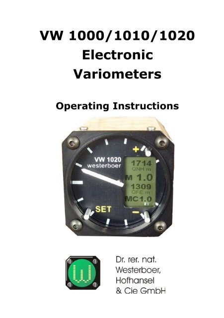
1 Installation1.1 IntroductionThe instruments <strong>VW</strong><strong>1000</strong>, <strong>VW</strong><strong>1010</strong> and <strong>VW</strong><strong>1020</strong> of thenew Variometer series feature a compact design, a simplehandling and the <strong>Westerboer</strong>-specific Variometer characteristics.Display of the vertical speed is effected by means of aneedle in a classic round instrument and can therefore bevery well read under any lighting conditions. The instruments<strong>VW</strong><strong>1010</strong> and <strong>VW</strong><strong>1020</strong> are additionally equippedwith a graphic LCD display. There a medium climb, altitudeindications, the real flying speed, temperature and batteryvoltage can be faded in.Due to the global approval by the aircraft manufacturer’sentry into the flight manuals, the <strong>Variometers</strong> of this seriesare appropriate for gliders. If altitudes and flying speedsare indicated, these are only supplements of the approvedmechanical instruments and shall not replace them in anycase.The principal characteristics of the three instrumenttypes are:<strong>VW</strong><strong>1000</strong>• TEK-compensated E-Vario<strong>VW</strong><strong>1010</strong>• TEK-compensated E-Vario• Averager<strong>VW</strong><strong>1020</strong>• <strong>Electronic</strong>ally compensated E-Vario• Averager• Speed commandIf in the following text Vario <strong>VW</strong>10xx is mentioned,the text applies to all three types <strong>VW</strong><strong>1000</strong>, <strong>VW</strong><strong>1010</strong> and<strong>VW</strong><strong>1020</strong>- -
1.2 Scope of Delivery••••••<strong>VW</strong>10xx E-Variometer- speed command / Vario changeover switch (only<strong>VW</strong><strong>1020</strong>)temperature sensor (only <strong>VW</strong><strong>1010</strong> and <strong>VW</strong><strong>1020</strong>)integrated loud speaker (in addition an external loudspeaker is available)cable for 12 V power supplyinstallation material1.3 Installation of the Variometer<strong>VW</strong>10xxThe Variometer is installed in a standard round cut-outof 57 mm in diameter. The used screws shall not extendmore than 15 mm into the instrument.When opening the cockpit canopy while the sun is at ahigh position, please bear in mind that the display might getdamaged by its burning glass effect.internal loudspeekerTEK probe /static pressure (<strong>VW</strong><strong>1020</strong>)total pressure (<strong>VW</strong><strong>1020</strong>)CAN interfaceD-SUB connection cable- -
Parameter Sequence <strong>VW</strong><strong>1010</strong>Parameter Value Range NoteAvg s 2 .. 120 s Integration time in secondsDampingConfig1 .. 3 Variometer damping;1: low damping2: medium damping3: high dampingWhen acknowledging with button”+”, you go to the ConfigurationParameterfolge <strong>VW</strong><strong>1020</strong>Parameter Value RangeNoteMC m/s 0 .. 6 MacCready Einstellung fürSollfahrtgeber in Schritten zu0.5 m/sAvg s 2 .. 120 s Integration time in secondsDamping 1 .. 3 Variometer damping;1: low damping2: medium damping3: high dampingWingLoad 20 .. 50 kg/m² Wing load; adjustable insteps of 0.5 kg/m²ConfigWhen acknowledging withbutton ”+”, you go to theConfiguration2.5 ScreenFollowing specifications refer to the instrument types<strong>VW</strong><strong>1010</strong> and <strong>VW</strong><strong>1020</strong>, both equipped with a LCD display.Status Display when Switching-onD When being switched on, on the display the instruments<strong>VW</strong><strong>1010</strong> and <strong>VW</strong><strong>1020</strong> show information on the serial- -
number of the instrument, the scaling and the unit of theVario display.Screen LayoutIn central position and in clearly biggerletters the medium climb is digitallydisplayed and marked with an ”M” put infront. In case of the <strong>VW</strong><strong>1020</strong> here in thespeed command mode the actual air massclimbing (Net vario) is displayed, markedwith an ”N” being inversely displayed fora better identification.Above and below the display of themedium climb, there are two parameterlines on the display that the user canprogram. The corresponding parametersin the Configuration are ”Top” and ”Bottom”. You can selectall altitude indications (STD, QNH, QFE) in foot and meters,temperature (°C and F), the battery voltage and in case ofthe <strong>VW</strong><strong>1020</strong> additionally the flying speed (TAS).Furthermore in case of the <strong>VW</strong><strong>1020</strong> the MacCready Valueis faded in on the bottom line.- -
3 ConfigurationAs mentioned before, parameter ”Config” is located atthe end of the main menu. When acknowledging with button”+”, you go to the Configuration menu. By pressing button”SET” instead, you go back to the Vario mode.If you don’t press any button for approx. 30 seconds,you will automatically leave the Configuration menuand return to the Vario mode. Also a manual change ispossible. For this keep button ”SET” pushed until parameter”Main” appears on the display. After acknowledgingwith button ”+”, you return to the Vario mode.If parameters have been modified in the Configuration menu,you must change to the Vario mode. Only then, modified parameterswill be permanently saved in the internal memory.If the power supply had been interrupted before, the originalvalues are maintained.3.1 Overvierw of Configuration <strong>VW</strong><strong>1000</strong>As <strong>VW</strong><strong>1000</strong> is not equipped with a display, the actualparameter and its value are indicated by the needle position– like in the main menu. Here also half steps are applied.After the actual value has been indicated that way, it can bemodified by pressing button ”+” resp. ”-”.Parameter No. Value NoteRangeVolume 3 0 .. 8 Volume when switching on0 = Audio off;8 = max. volumeUnits 4 0, 1 0=m/s; 1=ktsRange 5 0 .. 2 0=0..3; 1=0..6; 2=0..12Main 6 Go to the main menu bypressing button ”+”- -
3.2 Overvierw of Configuration <strong>VW</strong><strong>1010</strong>and <strong>VW</strong><strong>1020</strong>In case of the instruments <strong>VW</strong><strong>1010</strong> and <strong>VW</strong><strong>1020</strong> theparameters are shown on the display.Parameter Sequence <strong>VW</strong><strong>1010</strong>Parameter Value Range NoteLCD 0 .. 63 0=light display; 63=darkdisplayElev m 0 .. 2000 m Altitude of the takeoff placeUnits m/s, ktsMSLUnit of the Variometer displayand the averagerRange 0..3, 0..6,0..12TopBottomDisplay range of the roundscaleParameter shown at the topParameter shown at the bottomVolume 0 .. 8 Volume when switching on0 = Audio off8 = max. volumeMainGo to the main menu bypressing button ”+”Parameter Sequence <strong>VW</strong><strong>1020</strong>Parameter Value Range NoteLCD 0 .. 63 0=light display; 63=darkElev m 0 .. 2000 mdisplayAltitude of the takeoff placeUnits m/s, ktsMSLUnit of the Variometer displayand the averagerRange 0..3, 0..6,0..12Display range of the roundscale- 10 -
Parameter Value Range NoteComp -100 .. +100 Percentage deviation from theProbe static, TEKcoefficient 1Depending on the pressure atSTF Ptr STF, Nettothe upper pneumatic tubeIn the speed command mode:STF km/h 60 .. 300STF=needle indicates thespeed commandNet = needle shows net climbThreshold for speed-dependentspeed command switchoverTopBottomParameter shown at the topParameter shown at the bottomVolume 0 .. 8 Volume when switching on0 = Audio off8 = max. volumev1 km/h 10 .. 300 for determining the polarcurvew1 m/s -4.0 .. 0.0 for determining the polarv2 km/h 10 .. 300curvefor determining the polarw2 m/s -4.0 .. 0.0curvefor determining the polarv3 km/h 10 .. 300curvefor determining the polarw3 m/s -4.0 .. 0.0curvefor determining the polarWL kg/m2 10 .. 50curvefor determining the polarMaincurveGo to the main menu bypressing button ”+”- 11 -
3.3 Scaling and UnitsFor the international use, the <strong>Variometers</strong> <strong>VW</strong>10xx canindicate the climb in meters per second as well as in knots.Switching over is effected in the configuration menu. Thescaling must then be adjusted accordingly in order to beable to show a reasonable value range.On delivery, the standard setting of the unit is metersper second and of the range 0 to 6 m/s. Thus a scale divisioncorresponds to one meter per second.At the setting 0 .. 3 the <strong>VW</strong>10xx operates as precisionvariometer with 0.5 m/s per scale division. For being ableto monitor the selected unit and the value range, the actualsettings of these parameters are shown on the display of the<strong>VW</strong><strong>1010</strong> and the <strong>VW</strong><strong>1020</strong> when being switched on.3.4 AltimeterThe <strong>VW</strong><strong>1010</strong> and the <strong>VW</strong><strong>1020</strong> can show the flying altitudeon the display. Here all general reference menus (STD,QNH, QFE) and the units ”Meters” and ”Foot” can be selected.The setting is effected in the configuration by means of theparameters ”Top” and ”Bottom”.For QNH and QFE the altitude of the takeoff place aboveMSL must be entered in parameter ”Elev m” before takeoff.If you always take off at the same place, value input mustonly be effected once.The <strong>VW</strong><strong>1010</strong> is characterized by the fact that it is exclusivelyconnected to the TEC nozzle. The herewith measuredpressure corresponds to the static pressure in the flyingaltitude, less the impact pressure 1 . If you calculate the flyingaltitude hereby, different values depending on the flyingspeed will result, always misleadingly overvaluing the altitude.For obtaining reasonable altitude indications, in case ofthe <strong>VW</strong><strong>1010</strong> a constant is deducted from the measured valueso that the correct value will result at a flying speed of 120km/h. If you fly more slowly, the indicated altitude is lower(approx. 30 m at 85 km/h). As a result the indicated altitudewill be higher at higher speeds (30 m at 150 km/h).If the <strong>VW</strong><strong>1020</strong> is also connected to the TEC nozzle, thestatic pressure is calculated along with the value of the totalpressure. Therefore the altitude must not be corrected.- 12 -
3.5 Speed CommandIn case of the <strong>VW</strong><strong>1020</strong> you can change from the variomode to the speed command mode (STF Speed to Fly) bymeans of a changeover switch. Generally the changeoverswitch is mounted as toggle switch at the stick. Optionallyyou can mount a magnetic switch at the air brake leveragein case of a flapped glider so that changeover is effectedautomatically when modifying the flap position.It is however also possible to regulate the changeoverautomatically depending on the flying speed. For this youcan pre-select the threshold for the automatic changeover bymeans of parameter ”STF km/h” in the configuration. If theflying speed is higher than the threshold speed, the <strong>VW</strong><strong>1020</strong>will initiate the speed command mode. If you fall below thethreshold speed by more than 5 km/h, the automatic systemof the <strong>VW</strong><strong>1020</strong> will switch back to the vario mode.Switch-dependent and automatic changeover is logicallylinked with an OR function. If at least one of these two optionsis in speed command position, also the <strong>VW</strong><strong>1020</strong> will operatein the speed command mode. If you want to renounce of theautomatic system, you have to leave the threshold speed atthe maximum value of 300 km/h, that normally will not beexceeded. If you want to fly always in the automatic mode,you must leave the mechanical changeover switch in thevario position or generally renounce of mounting a switch atall. Then an open contact at the D-Sub plug is equivalent tothe vario mode of the mechanical changeover. In our experiencethe mechanical option is preferable as you can herewithavoid any frequent unintentional changeover when flyingat a speed around the threshold. The pilot should howeverdecide himself which method he prefers.The speed command depends on the true descent of theplane at a determined speed and the expected climb in thefollowing thermal. The true descent is taken from the polarcurve of the plane (entering the polar curve of the plane isspecified in the following), which applies to a determinedwing load, and the expected climb is entered as MacCreadyValue.If for the speed command mode the display has beenselected as speed command (parameter ”STF Ptr”), you must- 13 -
Optimum values of the variometer are achieved, whenthe modification of the static pressure caused by altitude losswhen gliding forward, is compensated by the impact pressureof the flying speed. In case of a TEC nozzle you speak of acoefficient ”1”. The <strong>VW</strong><strong>1020</strong> is programmed in such a waythat the pressures are compensating themselves similarly.In case of deviations from the exact ratio of the pressuremodifications, you must adjust the TEC nozzle - forexample by modifying the measuring holes. It is of coursemuch easier when using software. In <strong>VW</strong><strong>1020</strong> herefore parameter”Comp” is adjusted. In case of overcompensation,parameter ”Comp” is modified to negative, in case of undercompensationto positive.You can check the compensation by means of test flightsin calm air without thermals. Little measuring pressure reductionerrors can be compensated. In practice the ”pitchingup” is relevant.The measuring flights always start with a fixed startingspeed (e.g. v1 = 170 km/h as in the figure). Then for avoidingacceleration impacts quickly pitch up with a big radius toa lower speed v2 (e.g. 90 km/h).Ideally the variometer display exactly follows the polardescent (line 1). In case of an under-compensation, thenumber of vario deflections to the positive (line 3) rises. In- 15 -
Value Meaning <strong>VW</strong><strong>1010</strong> <strong>VW</strong><strong>1020</strong>QFE mAltitude above take-offplace in metersQFE ftAltitude above take-offplace in feetTAS kmh True air speed in km/h TAS kts True air speed in knots T C Temperature in °C T FTemperature in FahrenheitBat V Battery voltage in Volt - 17 -
4 Auxiliary Equipment4.1 Repeater <strong>VW</strong>1050 und <strong>VW</strong>1060At present auxiliary display units are available. The<strong>VW</strong>1050 is a pure needle instrument whereas the <strong>VW</strong>1060disposes of an additional LCD where the same parametersare displayed as in the instruments <strong>VW</strong><strong>1010</strong> and <strong>VW</strong><strong>1020</strong>.Both auxiliary display units are connected to the RJ45bushings (CAN interface) ofthe <strong>VW</strong>10xx Variometer bymeans of a patch cable. Inaddition to the data, thiscable is also in charge of thepower supply of the instruments<strong>VW</strong>1050 and <strong>VW</strong>1060.Therefore no additional powersupply is necessary.The scaling and the unitsof the needle are taken overwhen switching on Variometer<strong>VW</strong>10xx and in case of type<strong>VW</strong>1060 they are shown onthe display for a short time. When modifying parameterlines ”Top” and ”Bottom” of the <strong>VW</strong><strong>1010</strong> resp. <strong>VW</strong> <strong>1020</strong>,these modifications are transferred to the <strong>VW</strong>1060 and alsocarried out there.4.2 External LoudspeakerAn external loudspeaker is recommended in case ofdual seaters and planes whose instrument housing is closedall around.- 18 -
5 Technical DataCut-out in the instrumenthousingHousing dimensionsWeightSupply voltagePower input57 mm standard cut-outW = 60 mmH = 60 mmL = 98 mmapprox. 200g9 .. 18 V90 mA at a medium soundlevel- 19 -
- 20 -