Solder Practice Kit MODEL AK-100 - Carl's Electronic Kits
Solder Practice Kit MODEL AK-100 - Carl's Electronic Kits
Solder Practice Kit MODEL AK-100 - Carl's Electronic Kits

Create successful ePaper yourself
Turn your PDF publications into a flip-book with our unique Google optimized e-Paper software.
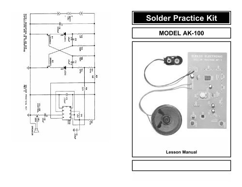
<strong>Solder</strong> <strong>Practice</strong> <strong>Kit</strong><strong>MODEL</strong> <strong>AK</strong>-<strong>100</strong>Lesson ManualElenco <strong>Electronic</strong>s, Inc.
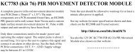
Parts ListContact Elenco <strong>Electronic</strong>s (address/phone/e-mail is at the back of thismanual) if any parts are missing or damaged. DO NOT contact yourplace of purchase as they will not be able to help you.ResistorsQty Symbol Description Part #1 R3 68Ω 5% 1/4W (blue-gray-black-gold) 1268002 R1, R7 470Ω 5% 1/4W (yellow-violet-brown-gold) 1347001 R2 1kΩ 5% 1/2W (brown-black-red-gold) 14<strong>100</strong>12 R8, R9 10kΩ 5% 1/4W (brown-black-orange-gold) 15<strong>100</strong>01 R5 47kΩ 5% 1/4W (yellow-violet-orange-gold) 1547002 R4, R6 56kΩ 5% 1/4W (green-blue-orange-gold) 1556001 VR1 200Ω Potentiometer 191321CapacitorsQty Symbol Description Part #2 C4, C5 .02µF Discap (203) or .022µF (223) 2422803 C1, C2, C3 10µF Electrolytic (Lytic) 2710451 C6 <strong>100</strong>µF Electrolytic (Lytic) 281044SemiconductorsQty Description Part #2 Transistor 2N3904 3239041 IC 555 or 1455 3305552 LED Red 350002MiscellaneousQty Description Part #1 Printed Circuit Board 5115001 Battery Snap 5900981 Speaker 59010212” Wire 8148001 <strong>Solder</strong>ing Iron 9SR11 Side Cutters 9ST11 <strong>Solder</strong> Roll 9ST48. When two adjacent foils accidentally touch, it is calledA. a jumper.B. a blob.C. a solder hole.D. a solder bridge.9. What ratio has the greatest amount of tin?A. 20/60B. 40/60C. 50/50D. 60/4010. A good solder connection should beA. dull and rough.B. shiny, bright and smooth.C. lumped around the connection.D. soldered on one side of the connection.Transistor 2N3904 IC 555 or 1455 LEDResistors Electrolytic Capacitor Ceramic Capacitor1/4W1/2WLytics havepolarity. Note themarking on theside beforemounting.+Answers: 1. B, 2. C, 3. A, 4. D, 5. B, 6. A, 7. C, 8. D, 9. D, 10. BFigure 1, Parts Identification-1- -10-
Quiz1. <strong>Solder</strong> is comprised of what two materials?A. gold and copper.B. tin and lead.C. zinc and copper.D. lead and aluminum.2. What type of flux should be used in electronics?A. chloride.B. organic.C. rosin.D. corrosive.3. When working on PC boards, what wattage range of iron is ideal?A. 15-40 watts.B. 50-<strong>100</strong> watts.C. 1-10 watts.D. <strong>100</strong>-200 watts.4. Tinning the soldering tip will prevent it fromA. heating.B. melting.C. soldering.D. oxidating.5. Proper solder adhesion requires that the metal surface to beA. solder free.B. clean.C. greasy.D. cold.6. <strong>Solder</strong> wick is used toA. remove solder.B. solder in small parts.C. cleaning the soldering iron tip.D. removing flux.7. A cold solder joint is caused byA. a solder bridge.B. using 60/40 solder.C. insufficient heat.D. acid core solder.-2--9-IntroductionAlmost every electronic device today has a printed circuit board whetheryou are assembling a PC board or repairing it, you must understand thebasics of working with these boards.A poorly soldered joint can greatly affect small current flow in circuits andcan cause equipment failure. You can damage a PC board or acomponent with too much heat or cause a cold solder joint withinsufficient heat. Sloppy soldering can cause bridges between twoadjacent foils preventing the circuit from functioning.Good soldering requires practice and an understanding of solderingprinciples. This solder practice project will help you achieve goodsoldering techniques, help you to become familiar with a variety ofelectronic components, and provide you with dynamic results. If thecircuit has been assembled and soldered properly, the LED willalternately flash and the speaker will produce a wailing sound.<strong>Solder</strong><strong>Solder</strong> is a fusible alloy composed of tin and lead. Some solder maycontain small amounts of other material for use in special purposes toenhance its characteristics. <strong>Solder</strong> has a melting temperature around360 O to 370 O , making it ideal for forming a metallic joint between twometals.<strong>Solder</strong> is identified by the ratio of tin-to-lead. The most common ratiosare 40/60, 50/50 and 60/40. <strong>Solder</strong> with a greater tin content melts at alower temperature, takes less time to harden, and generally makes iteasier to do a good soldering job. The ratio of tin is a main factor in thestrength of the solder joint. <strong>Solder</strong> with a greater tin content has a greaterholding ability under stress. <strong>Solder</strong> with a tin ratio of 60% is the strongest,while solder with less than 30% would be undesirable.FluxMost solder contains flux in the hollow core of the solder allowing it to beapplied automatically when you heat the solder. The flux will remove anyoxide film on the metals soldered creating a good metal-to-metal contact.This is called “wetting the metal”. There are three types of solder of solderfluxes: chloride, organic and rosin. In the electronics industry, only therosin type is used. Rosin flux comes in two types, pure and active. Themost reliable is the pure type, since it doesn’t cause dendrites betweentracks on the PC board as the active type does. Due to the highlycorrosive and moisture attracting characteristics of the chloride andorganic type fluxes, they should not be used in electronics.
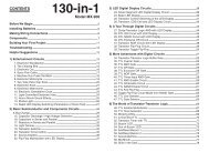
Types of <strong>Solder</strong>ing DevicesA number of different types of soldering devices: irons, guns and stationsare available today. Irons are used for light to medium work and guns arefor medium to heavy-duty work. The station type can range from light toheavy-duty. When working on PC boards, a soldering iron is ideal. Ironsizes vary from 15 to over 500 watts. For working on PC boards, ironsranging from 15 to 40 watts is suitable. If you use an iron with a higherwattage rating than 40 watt, you may damage the copper tracks on thePC board. The higher wattage irons are best suited for heavy-dutyelectrical jobs.<strong>Solder</strong>ing Iron <strong>Solder</strong>ing Gun <strong>Solder</strong>ing Station<strong>Solder</strong> TipsThe material that the tip is made from is an important factor. Most tips aremade of copper coated with some other material. The molten solder onthe tip will wear it down. To increase their lifetime, tip can be coated withiron, but this decreases the heat transfer rate. The tip should be tinnedby lightly coating it with solder. This will prevent it from oxidating. The tipbecomes pitted (black spots) from normal use. You can remove thesespots by scraping them with a knife or filing item. After removing thespots, you should re-tin the tip. It is important to clean the tip by wiping itwith a wet rag or sponge. A good clean solder tip makes soldering mucheasier.Today, tips are manufactured in a variety of different shapes (see figurebelow). The chisel shape is one of the most common. Having a choiceof tip styles allows you to choose the one best suited for your solderingneeds. Due to the high heat, removable tips can bond themselves to theheating element if left in place for extended periods of time. Periodicremoval of the tip is therefore advisable.Precision<strong>Electronic</strong>PencilChiselMicroSpadePyramidLong TaperChiselTaperedNeedleScrewdriverChiselSteppedChiselChiselForkTheory of OperationThe solder practice kit produces the sound of the European siren. Itconsists of two oscillators, a one hertz (one cycle per second) and a1500Hz. The one hertz oscillator consists of two transistors Q1 and Q2,and resistors R1, R2, R6 and R7 capacitors C1 and C2. Thisconfiguration is known as a multivibrator circuit.When voltage is first applied to this multivibrator circuit, one transistor(possibly Q1) will conduct faster, causing transistor Q2 to stay off. Q1 willcontinue to conduct until it saturates. At this point, Q2 will start to conduct,causing Q1 to rapidly cutoff. This process continues alternately causing Q1or Q2 to conduct. The output will be a square wave. The frequency isdetermined by the time constants of resistor R6 and capacitor C1, also R4and C2. Two LED diodes are placed in the collectors of the transistors andwill light when current is passing through them. Resistors R2, R1 and R7determine the current passing through the LEDs.Integrated circuit IC1 is the heart of the second oscillator. A 555 timer ICis used in the circuit. This IC contains many transistors and resistors ona silicon chip and thus eliminates many external parts. The frequency ofthis oscillator is determined by resistors R5, R9 and capacitor C4.Capacitor C3 couples the output of operations of IC1 via resistor R8. Thischanges the operations of IC1 during one half cycle of the multivibratorcausing the frequency to change from 1500Hz to 2200Hz. This results ina speaker output that varies constantly in pitch. The multivibrator circuitnot only causes the LED to flash, but also varies the pitch at the speakeroutput.TroubleshootingContact Elenco <strong>Electronic</strong>s (address/phone/e-mail is at the back of thismanual) if any parts are missing or damaged. DO NOT contact yourplace of purchase as they will not be able to help you.If you are experiencing a problem, first read the theory of operations tofamiliarize yourself with the operation. Remember, there are twooscillators. If no sound comes out of the speaker, but the LED flashesalternately, then the 555 timer is not working. Be sure that the volumecontrol is at maximum. Check the components IC1, R5, R8, R9, C3, C4and C5. Be sure that the IC is in properly.If a steady sound (not wobbling) comes out of the speaker, then themultivibrator is not working. Check the components associated withtransistor Q1 and Q2. Check the LED by shorting the transistor collectorto the emitter. The LED should light. If not, then the LED is either openor backwards.-3--8-
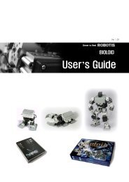
Circuit Board AssemblyNote that electrolytic capacitors, transistors, LEDs and the IC must beinstalled according to their polarity. Refer to Figure 1 for identification.Battery SnapRedBlackBattery SnapC5 - .02µF or .022µFDiscapC6 - <strong>100</strong>µF LyticNote polarityIC1 555 or 1455Note dot marking6” Wires (strip 1/4”off of both ends)VR1 200ΩVolume Control(these holes not used)R3 - 68Ω Resistor(blue-gray-blk-gold)R2 - 1kΩ 1/2W(brn-blk-red-gold)C2 - 10µF LyticNote polarityQ1, Q2 - 2N3904transistors (note flat)LED - Note flatFigure 3After completing the above assembly, twist the two speaker wires togetherand solder to speaker lugs.Cut 12” wire into two 6” wires.After completing the assembly of the kit, double back to see that thesoldering looks good and all of the components are in their proper place.If everything is all right, attach the 9V battery to the battery snap. TheLEDs should alternately light and the speaker should sound a wobblingsiren.-4--7-R9 - 10kΩ Resistor(brn-blk-orange-gold)R8 - 10kΩ Resistor(brn-blk-orange-gold)Jumper Wire, usecut-off from resistorsR7 - 470Ω Resistor(yel-vio-brn-gold)C3 - 10µF LyticNote polarityR6 - 56kΩ Resistor(grn-blue-org-gold)R5 - 47kΩ Resistor(yel-vio-org-gold)C4 - .02µF or .022µFDiscapR4 - 56kΩ Resistor(grn-blue-org-gold)C1 - 10µF LyticNote polarityR1 - 470Ω Resistor(yel-vio-brn-gold)Jumper WireLED - Note flatClean ConnectionsProper solder adhesion requires that the metal surface to be free of dirtand grease. The flux only removes the oxides so a brush or rag can beused to clean metal. There are contact cleaners in aerosol cans andother solvents available.DesolderingGreat care should be taken when repairing or correcting a mistake on aPC board. The metal foil can be easily pulled up or broken from excessiveheat. Use the least amount of heat as possible. You can use adesoldering tool, bulb, wick or a station. These tools will remove thesolder enabling you to correct the problem.Desoldering Tool<strong>Solder</strong>ing Components to the PC BoardA. A 15 to 40 watt pencil type soldering iron with a 1/8” or 3/16” pyramidworks well.B. The soldering iron tip must be kept clean at all times. Wipe it on a wetsponge or cloth, then tin the entire tip to give it a wet look. This willprevent the tip from oxidizing.C. Always use rosin core solder, type 60/40 (60% tin, 40% lead). Neveruse acid core solder, for it will damage the components.Component LeadFoil<strong>Solder</strong> Wick<strong>Solder</strong>ing IronCircuit BoardD. <strong>Solder</strong> all components from the copperfoil side only. Push the soldering iron tipagainst both the lead and the circuitboard foil.BulbDesoldering Station
<strong>Solder</strong>Foil<strong>Solder</strong>FoilRosinPoor solderconnection<strong>Solder</strong>ing Iron<strong>Solder</strong>ing Iron<strong>Solder</strong>ing ironpositioned incorrectly.<strong>Solder</strong>ing iron positionedincorrectly.E. Apply a small amount of solder to the irontip. This allows the heat to leave the ironand flow into the foil. Immediately applysolder to the opposite side of theconnection, away from the iron. Allow theheated component and circuit foil to meltthe solder.F. Allow the solder to flow around theconnection. Then, remove the solder andiron and let the connection cool. Thesolder should flow uniformly and not lumparound the wire. The connection should bebright, shiny and smooth.G. Poor solder connections occur when thelead is not heated sufficiently. This iscalled a “cold” solder joint. The solder willnot adhere to the lead as shown. Tocorrect this, reheat the connection and ifnecessary, apply a small amount ofadditional solder to obtain a goodconnection.H. When the foil is not heated sufficiently, thesolder will blob on the circuit board. Tocorrect this, reheat the connection and ifnecessary, apply a small amount ofadditional solder to obtain a goodconnection.I. A solder bridge may form if you accidentallytouch an adjacent foil, particularly apreviously soldered connection, use toomuch solder, or drag the soldering ironacross adjacent foils. Remove any solderbridges with your soldering iron.<strong>Solder</strong>ing Project ProcedureBefore we begin to assemble and solder components to the solderpractice board, we will practice large pads on the edge of the PC board,see Figure 2. <strong>Solder</strong>ing should be smooth and neat. Next, solder to thesmaller pads. Be sure that there is no solder bridging. Try intentionally tomake a solder bridge. Then, remove it by lifting the PC board over thesoldering iron and the iron will draw the solder away from the pads. It isbest to wipe the iron tip with a damp cloth to remove the solder. Finally,you will note the large rectangle pads. These are used to practice “tacksoldering”. Strip the end of the wire and practice soldering the wire to thepads. Remove the wire when finished.The PC board is covered with solder resist over areas that are not to besoldered. This is done to reduce soldering shorts to adjacent metal runs.On the large pad, note that half of the pad is covered with solder resist.Try soldering the wire to the covered pad. You will find that it is impossibleto solder.Tack <strong>Solder</strong>PadFigure 2 <strong>Practice</strong> <strong>Solder</strong> AreaRefer to Figure 3 and begin the PC board assembly with resistor R9. Besure to identify the correct value by reading the color code (brown-blackorange-gold).Place the resistor into the PC board with the leads comingout on the copper foil side. <strong>Solder</strong> in place and clip off the excess wireclose to the connection. Proceed clockwise with the other components.Check off the box when you have completed that step.J. Do not allow components to move whensolder is cooling. It may not solderproperly and result in a cold solder joint.Components should be placed as close tothe board as possible. Bend the leads tohold the part in place while soldering.-5--6-Large PadsSmall Pads