EC declaration of conformity
EC declaration of conformity
EC declaration of conformity

Create successful ePaper yourself
Turn your PDF publications into a flip-book with our unique Google optimized e-Paper software.
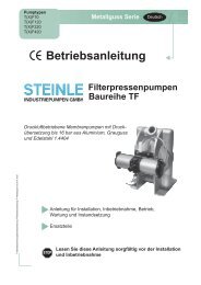
Edition 1/2010 C:\arbetsfiler\instruktioner\tapflo\pumpar\TF pumps\ TF PE & PTFE seris instruction manual english - 2010-1.indd<br />
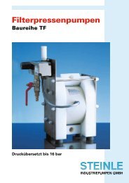
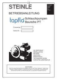
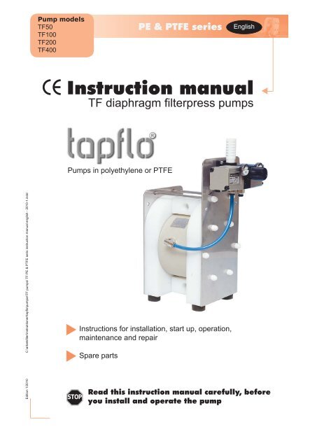
Pump models<br />
TF50<br />
TF100<br />
TF200<br />
TF400<br />
Instruction manual<br />
TF diaphragm filterpress pumps<br />
Pumps in polyethylene or PTFE<br />
STOP<br />
Instructions for installation, start up, operation,<br />
maintenance and repair<br />
Spare parts<br />
PE & PTFE series<br />
English<br />
Read this instruction manual carefully, before<br />
you install and operate the pump
CONTENTS<br />
CONTENTS 2<br />
CE CERTIFICATE 3<br />
0. GENERAL 4<br />
0.1 Introduction 4<br />
0.2 The warning symbols 4<br />
1. INSTALLATION 5<br />
1.1 Receiving inspection 5<br />
1.2 Storage 5<br />
1.3 Foundation 5<br />
1.4 Suction and discharge pipings 5<br />
1.4.1 Turnable connections 5<br />
1.4.2 Connection <strong>of</strong> suction pipe 5<br />
1.4.3 Connection <strong>of</strong> discharge pipe 5<br />
1.5 Air connection 5<br />
1.5.1 Air treatment system 6<br />
1.5.2 Pressure ratio 1:2 6<br />
1.6 Example <strong>of</strong> installation 6<br />
1.7 Scope <strong>of</strong> supply 7<br />
2. OPERATION 8<br />
2.1 Health and safety 8<br />
2.1.1 Protection 8<br />
2.1.2 Environments in danger <strong>of</strong> explosion - ATEX 8<br />
2.1.3 Air pressure 8<br />
2.1.4 Noise level 8<br />
2.1.5 Temperature hazards 9<br />
2.2 Before starting the pump 9<br />
2.3 Starting and operating 9<br />
2.3.1 Dry running 9<br />
2.3.2 Optimizing the pump lifetime 9<br />
2.4 Pump stopping 9<br />
3. MAINTENANCE 10<br />
3.1 When the pump is new or reassembled 10<br />
3.1.1 Performance test 10<br />
3.2 Routine inspection 10<br />
3.3 Complete inspection 10<br />
3.4 Location <strong>of</strong> faults 10<br />
3.5 Dismantling the pump 11<br />
3.5.1 Before the dismantling procedure 11<br />
3.5.2 Mainparts 11<br />
3.5.3 Valve seats and valve balls 11<br />
3.5.3 Centerblock with circlips (TF50, TF100) 12<br />
3.5.4 Centerblock with threaded air valve (TF200 and<br />
TF400) 13<br />
3.5.5 Maintenance <strong>of</strong> the booster 13<br />
3.6 Assembly <strong>of</strong> the pump 14<br />
3.6.1 Centerblock with circlips (TF50, TF100) 14<br />
3.6.2 Centerblock with threaded air valve (TF200 and<br />
TF400) 14<br />
3.6.3 Diaphragms 15<br />
3.6.3 Valve seats and valve balls 16<br />
3.6.4 Main unit assembly 17<br />
3.6.5 Test run and follow up draft 18<br />
Instruction manual TF PE & PTFE series pumps 2<br />
4. SPARE PARTS 19<br />
4.1 Stocking recommendation 19<br />
4.2 How to order parts 19<br />
4.3 Pump code 19<br />
4.4 Spare part drawing TF50 and TF100 20<br />
4.7 Spare part list TF50 and TF100 21<br />
4.8 Spare part drawing TF200 and TF400 22<br />
4.9 Spare part list TF200 and TF400 23<br />
5. DATA 24<br />
5.1 Capacity curves 24<br />
5.2 Capacity changes 24<br />
5.3 Dimensions 25<br />
5.4 Technical data 26<br />
5.5 Tightening torques 26<br />
6. WARRANTY & REPAIR 27<br />
6.1 Returning parts 27<br />
6.2 Warranty 27<br />
6.3 Warranty form 29
CE CERTIFICATE<br />
Declaration <strong>of</strong> <strong>conformity</strong><br />
Machinery directive 2006/42/<strong>EC</strong><br />
Tapflo AB declares that:<br />
Product name: Filterpress diaphragm pumps<br />
Models: TF…<br />
Is in <strong>conformity</strong> with the essential health and safety requirements and technical construction<br />
file requirements <strong>of</strong> the <strong>EC</strong> Machinery directive 2006/42/<strong>EC</strong>.<br />
Manufacturer: Tapflo AB<br />
Address: Filaregatan 4<br />
S-442 34 Kungälv<br />
Sweden<br />
Tapflo AB, January 2:nd 2010<br />
Håkan Ekstrand<br />
Managing director<br />
Instruction manual TF PE & PTFE series pumps 3
0. GENERAL<br />
0.1 Introduction<br />
The Tapflo Air Operated Diaphragm Pump range is a complete serie <strong>of</strong> pumps for industrial applications.<br />
The pumps are designed to be safe simple and easy to use and maintain. The construction<br />
is sealless and without rotating parts. The pumps are suitable for almost all different chemicals<br />
used by the industry today..<br />
With proper attention to maintenace, Tapflo Pumps will give efficient and trouble free operation.<br />
This instruction manual will familiarise operators with detailed information about installing, operating<br />
and maintaining the pump.<br />
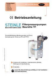
0.2 The warning symbols<br />
The following warning symbols are present in this instruction manual. This is what they say.<br />
STOP<br />
!<br />
This symbol stands next to all safety instructions in this instruction manual where danger<br />
to life and limb may occur. Observe these instructions and proceed with utmost caution<br />
in these situations. Inform also other users <strong>of</strong> all safety instructions. In addition to the<br />
instructions in this instruction manual, the general safety and accident prevention regulations<br />
must be observed.<br />
This signal stands at points in this instruction manual <strong>of</strong> particular importance for compliance<br />
with regulations and directives, for correct work flow and for the prevention <strong>of</strong><br />
damage to and destruction <strong>of</strong> the complete pump or its subassemblies.<br />
Instruction manual TF PE & PTFE series pumps 4
1. INSTALLATION<br />
1.1 Receiving inspection<br />
Although precaution is taken by us when packing and shipping, we urge you to carefully check the<br />
shipment on receipt. Make sure that all parts and accesories listed on the packing list are accounted<br />
for. Immediately report any damage or shortage to the transport company and to us.<br />
1.2 Storage<br />
If the equipment is to be stored prior to installation, place it in a clean location. Do not remove the<br />
! protective covers from the suction, discharge and air connections which have been fastened to<br />
keep pump internals free <strong>of</strong> debris. Clean the pump thoroughly before installation.<br />
1.3 Foundation<br />
The pump is furnished with vibration absorbing rubber feet. The pump will operate properly without<br />
being fixed to a foundation. If fixation is needed for an installation, make sure the foundation is<br />
! able to absorb vibrations. It is essential for the operation <strong>of</strong> the pump to mount the pump with the<br />
feet in a downward direction (see sketch).<br />
1.4 Suction and discharge pipings<br />
Suction and discharge piping should be fully supported and anchored near to but independent <strong>of</strong><br />
the pump. The piping to the pump should be a hose, to prevent undue stress and strain on the<br />
pump connections and the pipings.<br />
1.4.1 Turnable connections<br />
The suction and discharge connections are turnable 180°. This simplifies the assembling and<br />
installation considerably. If you wish to turn the connections, screw a threaded nipple into the<br />
connection and turn. On the larger models TF200 and TF400 it will simplify if the housing nuts are<br />
slightly released while turning the connections.<br />
1.4.2 Connection <strong>of</strong> suction pipe<br />
Remember that the suction pipe/connection is the most critical point, especially if the pump is<br />
priming. Just a small leakage will dramatically reduce the suction capability <strong>of</strong> the pump. When<br />
connecting the suction pipe, following is recommended.<br />
1) For satisfactory operation, use reinforced hose or corresponding (the suction power may otherwise<br />
shrink the hose). The internal diameter <strong>of</strong> the hose should be the same as on the suction<br />
connection (at the bottom <strong>of</strong> the pump) to have best suction capability.<br />
2) Make sure that the connection hose - pump is completely tight, otherwise the suction capability<br />
will be reduced.<br />
3) Always use as short suction pipe as possible. Avoid air pockets which can arise with long pipings.<br />
1.4.3 Connection <strong>of</strong> discharge pipe<br />
For this connection it is only recommended a simple and positive flow connection. Use a hose or<br />
STOP<br />
flexible piping (minimum one meter) between the discharge connection and any rigid fixed piping.<br />
Coil the hose at least one turn. All components (hose, pipe, valves etc) on the discharge piping<br />
must be designed for minimum PN 16.<br />
1.5 Air connection<br />
Screw the air hose into the air intake on the center block <strong>of</strong> the pump with for example a bayonet<br />
coupling. For best efficiency, use the same hose diameter as the internal diameter <strong>of</strong> the connection<br />
on the air intake.<br />
Instruction manual TF PE & PTFE series pumps 5
1. INSTALLATION<br />
1.5.1 Air treatment system<br />
The air valve is constructed for oilfree air. Lubrication <strong>of</strong> the air is not allowed. However, if the<br />
! air is very dry (laboratory air), the air may be lubricated with water. For TF50-TF100 maximum<br />
air pressure is 8 bar, for TF200-TF400 maximum air pressure is 6 bar. As prevention purpose, a<br />
filtration <strong>of</strong> the air by means <strong>of</strong> a 5 micron filter or finer is recommended. Dirt in the air can under<br />
unfortunate circumstances be the cause <strong>of</strong> breakdown. Recomended air quality according to PN-<br />
ISO8573 is particles class 3, water class 4 and oil class 3 .<br />
To facilitate the operation <strong>of</strong> the pump we recommend an air treatment system connected to the<br />
air supply. These components should be included:<br />
1) Regulator to adjust the air pressure<br />
2) Manometer to read the actual pressure<br />
3) Needle valve to adjust the air flow<br />
4) Filter<br />
These components are included in Tapflos Air treatment system which can be ordered from<br />
us.<br />
1.5.2 Pressure ratio 1:2<br />
The pressure booster has the function to transmit the primary pressure (from air source) to an<br />
outgoing pressure <strong>of</strong> up to the double. The pressure ratio between primary and secondary side<br />
is 1:2.<br />
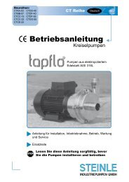
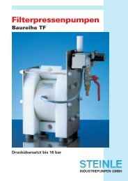
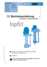
1.6 Example <strong>of</strong> installation<br />
Slurry<br />
tank<br />
Decompression pipe<br />
Air supply<br />
Booster<br />
TF filterpress pump<br />
Instruction manual TF PE & PTFE series pumps 6<br />
Filterpress
1. INSTALLATION<br />
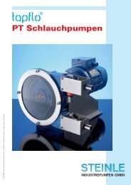
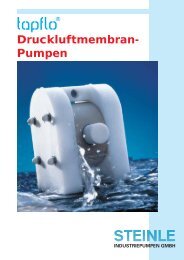
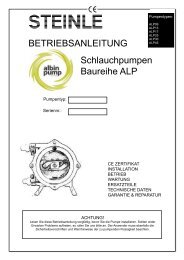
1.7 Scope <strong>of</strong> supply<br />
Product discharge side<br />
Instruction manual TF PE & PTFE series pumps 7<br />
Muffler booster<br />
Pressure booster<br />
Pressure gauge (option)<br />
Pressure adjustment knob<br />
Air connection<br />
Product suction side
2. OPERATION<br />
2.1 Health and safety<br />
The pump must be installed according to local and national safety rules.<br />
STOP<br />
The pumps are constructed for particular applications. Do not use the pump on applications<br />
different from that for which it was sold without consulting us to ascertain its suitability.<br />
2.1.1 Protection<br />
In the interest <strong>of</strong> health and safety it is essential to wear protective clothing and safety goggles<br />
STOP when operating, and/or working in the vicinity <strong>of</strong> Tapflo pumps.<br />
2.1.2 Environments in danger <strong>of</strong> explosion - ATEX<br />
The standard PE or PTFE series pumps are not allowed to operate in environments in danger <strong>of</strong><br />
STOP explosion. Static electricity may occur in the pump under operation, which may cause explosion and<br />
injury. Special conductive pumps TXF are available for such applications. If you have purchased<br />
a TXF pump, follow below instructions and local/national rules for safe use.<br />
ATEX (directive 94/9/<strong>EC</strong>) classification <strong>of</strong> Tapflo TXF pumps:<br />
IIB 2GD c T4<br />
Group II, explosive athomspheres<br />
(other than mines),<br />
gas group B (ethylene)<br />
Epsilon protected<br />
equipment<br />
Earth connection <strong>of</strong> pump and other equipment<br />
Connect a suitable earth wire to the stainless steel earth connection that is placed on the inside<br />
<strong>of</strong> one <strong>of</strong> the pump housings. Connect the other end <strong>of</strong> the earthwire to earth and also make sure<br />
that other equipment like hoses/pipes/containers etc are properly earthed/connected.<br />
2.1.3 Air pressure<br />
The maximum air pressure for Tapflo pumps is 8 bar. Higher air pressure than 8 bar can damage<br />
the pump and may cause injury to personel in vicinity <strong>of</strong> the pump. If you intend to apply a higher<br />
air pressure than 8 bar, please consult us.<br />
2.1.4 Noise level<br />
At tests, the noise level from a Tapflo pump has not exceeded 80 dB(A). Under some circumstan-<br />
STOP ces, for example if the pump is operating under high air pressure at low discharge head, the noise<br />
can be inconvenient or hazardous for personel staying for long periods in vicinity <strong>of</strong> the pump.<br />
This hazard can be prevented by:<br />
- using suitable ear protection<br />
- lower the air pressure and/or raise the discharge head<br />
- lead the outcomming air from the place by connecting a hose from the muffler connection <strong>of</strong><br />
the pump.<br />
- use elastomer valve balls (EPDM, NBR or polyurethane) instead <strong>of</strong> PTFE, ceramic or stainless<br />
steel, provided that the elastomer is compatible with the pumped liquid.<br />
Instruction manual TF PE & PTFE series pumps 8<br />
Type <strong>of</strong> protection, constructional<br />
safety<br />
Category 2, equipment providing<br />
high level <strong>of</strong> protection<br />
in areas where explosive<br />
athmosphere is likely to<br />
occur. G=gas, D=Dust.<br />
Temperature class, max<br />
surface temperature 135°C,<br />
ignition temperature <strong>of</strong> gas/<br />
vapour 135-200°C.
2. OPERATION<br />
2.1.5 Temperature hazards<br />
Raised temperature can cause damage on the pump and/or pipings and may also be hazardous<br />
STOP for personel in the vicinity <strong>of</strong> the pump/pipings. Avoid quick temperature changes and do not<br />
exceed the maximum temperature specified when the pump was ordered. See also general max<br />
temperatures based on water in chapter 5 "Data".<br />
2.2 Before starting the pump<br />
STOP<br />
!<br />
- Make sure the pump is installed accordning to the installation instruction (section 1).<br />
- Filling <strong>of</strong> the pump with liquid before start is not necessary.<br />
- When installation is new or reinstalled, a test run <strong>of</strong> the pump with water should be conducted<br />
to make sure the pump operates normally and does not leak.<br />
- When installation is new or reinstalled, check the pump housing nut tightening torque (see<br />
chapter 5.5 "Data"). After approx 1 week operation, the torque should be checked again. This<br />
is important to prevent leakage.<br />
2.3 Starting and operating<br />
- Open the discharge valve.<br />
- Note! Considering the suction capacity when air is still in the suction pipe, it is recommended<br />
to start with low air pressure/flow in the beginning. This is not necessary if the<br />
pump is filled with liquid before start.<br />
- When the pump has been filled with liquid, the air pressure/flow may be raised to increase the<br />
suction capacity <strong>of</strong> the pump.<br />
- The performance <strong>of</strong> the pump can be adjusted through the air supply by using a needle valve<br />
and a pressure regulator. The performance can also be adjusted by normal flow control on the<br />
discharge side <strong>of</strong> the system.<br />
2.3.1 Dry running<br />
The pump may run dry without any problem for shorter periods. Dry running for a longer period<br />
causes an increase <strong>of</strong> wear due to the high stroke frequency.<br />
2.3.2 Optimizing the pump lifetime<br />
Running at full frequenzy (maximum air pressure/flow) continiously will cause premature wear <strong>of</strong><br />
the components. As a general rule, we recommend to run at half <strong>of</strong> the maximum capacity <strong>of</strong> the<br />
pump. For instance, a TF100 pump should run continious maximum at 60 l/min.<br />
2.4 Pump stopping<br />
When the filter press is filled and the maximum pressure is reached, it must be stopped by closing<br />
the air supply. Before the filter press is opended, the pressure has to drop down to 0.<br />
To stop the pump automatically, various solenoid valves are available.<br />
Stroke sensors can register the frequency <strong>of</strong> the pump. When the end pressure is reached, the<br />
pump moves slowly and a signal for stopping the filtration can be given.<br />
Instruction manual TF PE & PTFE series pumps 9
3.1 When the pump is new or reassembled<br />
If the pump is new or reassembled after maintenance it is important to retighten the pump housing<br />
nuts (pos 37) after a few days <strong>of</strong> operation. Make sure to use the right torque, see chapter 5.5.<br />
!<br />
3. MAINTENANCE<br />
3.1.1 Performance test<br />
When installation is new, a test run <strong>of</strong> the pump should be conducted. Gauge the capacity at specific<br />
air pressure/flow. This information is for use in checking performance as wear takes place.<br />
You will be able to set schedules for maintenance <strong>of</strong> the pump and to select spare parts to be<br />
kept on stock.<br />
3.2 Routine inspection<br />
Frequent observation <strong>of</strong> the pump operation is recommended to detect problems. A change in<br />
! sound <strong>of</strong> the running pump can be an indication <strong>of</strong> weared parts (see below "location <strong>of</strong> faults").<br />
Leaking liquid from the pump and changes <strong>of</strong> performance may also be detected. Routine inspections<br />
should be conducted frequently.<br />
3.3 Complete inspection<br />
The intervals for a complete inspection depend upon the operation conditions for the pump. The<br />
! characteristics <strong>of</strong> the liquid, temperature, materials used in the pump and running time decide how<br />
<strong>of</strong>ten a complete inspection is necessary.<br />
If a problem has occured, or if the pump is in need <strong>of</strong> a complete inspection, see later this chapter<br />
"location <strong>of</strong> faults" and "dismantling <strong>of</strong> the pump". You are <strong>of</strong> course warmly welcome to consult<br />
us for further help.<br />
Worn parts should be carried in stock, see our recommendation in chapter 4.4.<br />
3.4 Location <strong>of</strong> faults<br />
Problem Possible fault<br />
The pump does not run The air pressure is to low<br />
The air connection is blocked<br />
Muffler is blocked<br />
Air valve is defect<br />
Dirt in the pump chamber<br />
Diaphragm breakdown<br />
The suction is bad Suction connection is not tight<br />
Suction connection is blocked<br />
Muffler is blocked<br />
Valve balls are blocked<br />
Valve balls are damaged<br />
The pump runs irregularly Valve balls are blocked<br />
Sealings are defect in air valve or center block<br />
Diaphragm breakdown<br />
Bad flow/pressure Pressurefall in incomming air<br />
Suction or air connection blocked<br />
Muffler is blocked<br />
Air valve is defect<br />
Valve balls worn out/broken<br />
Air in liquid<br />
Diaphragm breakdown<br />
Liquid leaks from the pump Screws on the housing not properly fastened<br />
Liquid comes out <strong>of</strong> the muffler Diaphragm breakdown<br />
Instruction manual TF PE & PTFE series pumps 10
3. MAINTENANCE<br />
3.5 Dismantling the pump<br />
The numbers put in brackets, refer to the part numbers in the spare part drawings and spare part<br />
lists in chapter 4.<br />
3.5.1 Before the dismantling procedure<br />
STOP<br />
Be sure to drain all liquid from the pump. Cleanse or neutralize the pump thoroughly. Disconnect<br />
the air connection and then the suction and discharge connections.<br />
3.5.2 Mainparts<br />
3.5.3 Valve seats and valve balls<br />
Fig 2. To remove the spacer sleeve (19), use a<br />
piece <strong>of</strong> plastic and a hammer to carefully knock<br />
to turn it.<br />
Fig 4. Carefully pull out the the spacer sleeve<br />
(19). Please note that force never shall be used<br />
for dismantling.<br />
Instruction manual TF PE & PTFE series pumps 11<br />
Fig 1.<br />
First pull out the air hose from the booster to<br />
the pump.<br />
Unscrew the housing nuts (37). Carefully pull<br />
out the pin screws (14). Lay the pump with<br />
one housing facing down and carefully lift the<br />
loose housing (11).<br />
Carefully lift the suction and discharge connections<br />
(13) and the center block (12) from the<br />
remaining housing (11).<br />
Fig 3. Put one <strong>of</strong> the pin screws in the hole <strong>of</strong> the<br />
spacer sleeve (19) and turn it all the way 180°.<br />
Fig 5. Pull out the lower valve seat (21) by means<br />
<strong>of</strong> one <strong>of</strong> the pin screws.
3. MAINTENANCE<br />
Fig 9. Press the diaphragms (15) to their neutral<br />
position (both have the same distance to<br />
the center block). Hold one <strong>of</strong> the diaphragms<br />
(15) and unscrew the other. Then pull out the<br />
remaining diaphragm (15) with the diaphragm<br />
shaft (16).<br />
Instruction manual TF PE & PTFE series pumps 12<br />
Fig 6. Push out the upper valve seat (20), be<br />
careful not to damage the edge <strong>of</strong> the connection<br />
hole.<br />
In order to remove the valve ball (23) from the<br />
valve seat, use a pin screw and press carefully<br />
out the valve ball stopper (22) and the valve ball<br />
will be free.<br />
3.5.3 Centerblock with circlips (TF50, TF100)<br />
This instruction applies to above mentioned pumps and older models <strong>of</strong> TF200 (serial numbers<br />
0803 and earlier) and TF400 (serial numbers 0801 and earlier).<br />
Fig 11. Carefully remove the circlip (27) with<br />
a circlip plier. While doing this, cover with your<br />
other hand, the circlip easily flips away! Do the<br />
same with the circlip (27) on the other side.<br />
Fig 10. If the shaft sealings (36) seem to be worn<br />
out (by internal leakage <strong>of</strong> air), carefully remove<br />
them with a pointed tool. During this operation,<br />
the sealing (36) and backup o-ring (47) usually<br />
get destroyed, so make sure to have replacement<br />
spares available.<br />
Fig 12. Press out the air valve (61) by means<br />
<strong>of</strong> a pressing device. Be careful not to damage<br />
the brass edges <strong>of</strong> the air valve.
3. MAINTENANCE<br />
3.5.4 Centerblock with threaded air valve (TF200 and TF400)<br />
Remove diaphragms (15), diaphragm shaft (16) and shaft seals (36) as described in fig 9-10.<br />
Fig 13. Carefully unscrew the air valve endcap<br />
by means <strong>of</strong> the mounting tool (282). Do the<br />
same with the endcap on the other side.<br />
Fig 15. To push out the cylinder, use the other<br />
side <strong>of</strong> the mounting tool that fit into the cylinder.<br />
Check seals and brass parts for wear or damage. If these are worn or damaged, replace the<br />
complete air valve assembly. If you are able to re use the air valve, replace the external o-rings<br />
(6 pcs pos 30) with new ones prior to assembly.<br />
3.5.5 Maintenance <strong>of</strong> the booster<br />
A seal kit is available for the booster and can be ordered from us. A maintenance instruction is<br />
included with this seal kit.<br />
Instruction manual TF PE & PTFE series pumps 13<br />
Fig 14. Now when both endcaps are removed,<br />
push out by hand the shaft and piston.<br />
Fig 16. Press out the cylinder, be careful not to<br />
damage the edges <strong>of</strong> the cylinder.
3. MAINTENANCE<br />
3.6 Assembly <strong>of</strong> the pump<br />
3.6.1 Centerblock with circlips (TF50, TF100)<br />
This instruction applies to above mentioned pumps and older models <strong>of</strong> TF200 (serial numbers<br />
0803 and earlier) and TF400 (serial numbers 0801 and earlier).<br />
Fig 1. Mount the circlip (27) on one side.<br />
3.6.2 Centerblock with threaded air valve (TF200 and TF400)<br />
Fig 3. Carefully screw the endcap by hand<br />
into the centerblock. Sometimes you have to<br />
first screw counter clockwise until the threads<br />
match.<br />
Instruction manual TF PE & PTFE series pumps 14<br />
Fig 2. Put a little water on the o-rings (30), other<br />
lubricants should not be used. Carefully push the<br />
air valve (61) into the housing. Mount the circlip<br />
(27) on the remaining side (see fig. 1).<br />
Fig 4. Tighten carefully by means <strong>of</strong> the mounting<br />
tool (pos 282) and a spanner.
3. MAINTENANCE<br />
Fig 5. Place one <strong>of</strong> the o-rings (pos 30) on the<br />
endcap.<br />
Fig 7. Place the last o-ring (pos 30) on the<br />
cylinder.<br />
3.6.3 Diaphragms<br />
Fig 9. Insert the shaft seal o-rings (47) in the<br />
groove.<br />
Instruction manual TF PE & PTFE series pumps 15<br />
Fig 6. Make sure all four o-rings (pos 30) are<br />
mounted on the cylinder. Use a little water on the<br />
o-rings to easier slide the cylinder into the centerblock.<br />
Other lubricants should not be used.<br />
Fig 8. Carefully mount the piston and shaft<br />
by hand. Repeat steps Fig 3 and Fig 4 on the<br />
remaining side. Carefully secure the endcaps<br />
equally on both sides.<br />
Fig 10. To mount the shaft seal (36), bend it<br />
to a kidney shape and insert carefully to the<br />
groove.
3. MAINTENANCE<br />
Fig 11. Mount the pin screw (part <strong>of</strong> the diaphragm<br />
shaft pos 16) securely in the diaphragm<br />
(15) by means <strong>of</strong> an allen key.<br />
3.6.3 Valve seats and valve balls<br />
Fig 13. Place the valve ball (23) in the lower<br />
valve seat (21) and mount the ball stop (22).<br />
Mount the valve seat o-ring (43) at the bottom<br />
<strong>of</strong> the seat (21)<br />
Fig 15. Mount the upper seat assembly; upper<br />
seat (20), valve ball (23), ball stop (22) and oring<br />
(43).<br />
Instruction manual TF PE & PTFE series pumps 16<br />
Fig 12. Mount the diaphragm shaft (16) on the<br />
diaphragm (15) and push the assembly carefully<br />
through the hole in the centerblock (12).<br />
Fig 14. Push the lower valve seat assembly into<br />
the housing (11)<br />
Fig 16. Place the spacer sleeve (19) upside<br />
down and press it up towards the the upper<br />
valve seat (20).
3. MAINTENANCE<br />
Fig 17. Put one <strong>of</strong> the pin screws into the hole <strong>of</strong><br />
the spacer sleeve (19) and turn it gently. Knock<br />
also carefully with a plastic hammer to easier<br />
force down the spacer sleeve.<br />
3.6.4 Main unit assembly<br />
Fig 20. Make sure all pin screws (14) have one<br />
nut (37) and one washer (38) each. Nut should<br />
only be put on one or two threads. Put the pin<br />
screws through the housing and the stainless<br />
steel side plate and mount carefully the center<br />
block assembly.<br />
Instruction manual TF PE & PTFE series pumps 17<br />
Fig 18. Make sure the seat and sleeve assembly<br />
is flat inside the housing.<br />
Fig 21. Put the small o-ring (pos 18) in the seat <strong>of</strong><br />
the housing. On pumps with PTFE diaphragms<br />
the PTFE u-ring with its o-ring shall be mounted<br />
with o-ring facing upwards (see Fig. 21).
3. MAINTENANCE<br />
Fig 22. Put on the inlet and outlet connections<br />
(13), make sure all o-rings (18) are mounted.<br />
Instruction manual TF PE & PTFE series pumps 18<br />
Fig 23. Carefully lift on the remaining housing<br />
and the stainless steel side plate with booster.<br />
Fig 24. Fasten the nuts (37) alternatingly, with<br />
or without washers depending on how much <strong>of</strong><br />
the thread comes out. If some <strong>of</strong> the nuts were<br />
fastened without washer, unscrew thoose and<br />
put washers underneath. Tighten the nuts according<br />
to recommended tightening torques in<br />
chapter 5.<br />
3.6.5 Test run and follow up draft<br />
We recommend you to conduct a test run <strong>of</strong> the pump before installing it to the system so no<br />
liquid gets wasted if the pump leaks or perhaps does not start according to wrong assembling <strong>of</strong><br />
the pump.<br />
!<br />
After a few weeks operation a follow up draft <strong>of</strong> the nuts is recommended.
4. SPARE PARTS<br />
4.1 Stocking recommendation<br />
Even at normal operation some details in the pump will be subject to wear. In order to avoid expensive<br />
breakdowns we recommend having a few spare parts in stock.<br />
Depending on the severity <strong>of</strong> the operation and the importance <strong>of</strong> not having a breakdown we <strong>of</strong>fer<br />
two different spare part sets.<br />
Set No 1<br />
Qty Description Pos<br />
2 Diaphragm 15<br />
4 Valve ball 23<br />
1 Muffler 25<br />
4 O-ringset 18<br />
4.2 How to order parts<br />
When ordering spare parts for Tapflo Pumps, please let us know the model number from the<br />
nameplate <strong>of</strong> the pump. Then just indicate the part numbers (refered to the spare part list) and<br />
quantity <strong>of</strong> each item.<br />
4.3 Pump code<br />
The model number on the pump tells the pump size and material <strong>of</strong> the pump components.<br />
Instruction manual TF PE & PTFE series pumps 19<br />
Set No 2<br />
*** = For TF100<br />
**** = Not TF200 (from serial No 0803) and TF400 (from serial No 0801)<br />
Tapflo diaphragm pump<br />
Special execution:<br />
A = Optional centerblock material<br />
E = Valve seat insert (PU, PTFE or<br />
AISI 316)<br />
F = Filterpress pump<br />
M = Optional connection type<br />
N = Optional material o-rings (pos 18)<br />
S = Optionsl material air valve<br />
V = AISI 316L valve seat / spacer<br />
X = ATEX approved, group II, cat 2<br />
Qty Description Pos<br />
1 Spare part set No 1 -<br />
1 Diaphragm shaft 16<br />
2 Upper valve seat 20<br />
2 Lower valve seat 21<br />
2 Spacer sleeve 19<br />
2**** Circlip 27<br />
2 Center block seal 36<br />
4 O-ring valve seat 43<br />
2*/4*** O-ring 47<br />
1 Air valve complete 61<br />
1 Booster seal kit 995<br />
Max capacity (l/min) Material <strong>of</strong> wetted thermoplastic<br />
parts:<br />
P = PE (polyethylene)<br />
T = PTFE<br />
T AF 50 P T T<br />
Material <strong>of</strong> diaphragms:<br />
E = EPDM<br />
N = NBR (nitrile rubber)<br />
T = PTFE<br />
V = FKM (certain models)<br />
Material <strong>of</strong> valve balls:<br />
E = EPDM<br />
N = NBR (nitrile rubber)<br />
T = PTFE<br />
S = AISI 316 stainless steel<br />
U = PU (polyurethane)<br />
K = Ceramic
4. SPARE PARTS<br />
4.4 Spare part drawing TF50 and TF100<br />
Divided seats<br />
991<br />
202 212 21<br />
222 222<br />
99<br />
Instruction manual TF PE & PTFE series pumps 20<br />
994<br />
147<br />
1172<br />
1171<br />
Flange connections<br />
70<br />
71/73
Pos Description Qty Material options<br />
11 Housing 2 PE or PTFE<br />
1171 Reinforcement plate long 1 AISI 316<br />
1172 Reinforcement plate short 1 AISI 316<br />
12 Center block 1 PP<br />
13 In/Outlet 2 PE or PTFE<br />
14 Pin screw 8 AISI 304<br />
15 Diaphragm 2 EPDM, PTFE, NBR or FKM*<br />
16 Diaphragm shaft 1 AISI 316<br />
17 Rubber foot 4 NBR<br />
18 O-ring set (in/outlet) 4 PTFE/EPDM, EPDM, FKM, NBR or FEP<br />
19 Spacer sleeve 2 PE or PTFE<br />
20 Upper valve seat 2 PE or PTFE***<br />
21 Lower valve seat 2 PE or PTFE***<br />
22 Valve ball stop 4 PE** or PTFE<br />
23 Valve ball 4 EPDM, PTFE, NBR, FKM AISI 316, PU or ceramic<br />
25 Muffler 1 PP<br />
26 Air intake adapter 1 Galvanized brass<br />
27 Circlip 2 Phosphor bronze<br />
30 O-ring 6 NBR (standard), EPDM or FKM<br />
33 Plug 2 PE or PTFE<br />
36 Center block sealing 2 PE<br />
37 Nut 16 AISI 304<br />
38 Washer 16 AISI 304<br />
43 O-ring (valve seat) 4 EPDM, PTFE or FKM<br />
47 O-ring (back up for 36) 2*/4** NBR (standard), EPDM or FKM<br />
57 Nut cover 16 PP<br />
61 Air valve complete 1 Body brass (standard), AISI 316 or PET, o-rings NBR (standard), EPDM or FKM<br />
99 Booster set complete 1 -<br />
991 Muffler booster 1 PP<br />
994 Pneumatic hose 1 PA<br />
995 Booster seal kit 1 -<br />
Options<br />
4. SPARE PARTS<br />
4.7 Spare part list TF50 and TF100<br />
Divided seats ***<br />
202 Upper sleeve (divided seat) 2 PE or PTFE<br />
212 Lower sleeve (divided seat) 2 PE or PTFE<br />
222 Valve seat (divided seat) 4 PE, PTFE, PU or AISI 316<br />
Flange connections<br />
70 Flange pipe (threaded) 2 PE or PTFE<br />
71 Loose flange ring ANSI 2 PP, PTFE or AISI 316<br />
73 Loose flange ring DIN 2 PP, PTFE or AISI 316<br />
* = TF50 only<br />
** TF100 only<br />
*** = Divided seat type standard on PTFE pumps<br />
Instruction manual TF PE & PTFE series pumps 21
4. SPARE PARTS<br />
4.8 Spare part drawing TF200 and TF400<br />
Divided seats<br />
202 212 21<br />
991<br />
222 222<br />
99<br />
Instruction manual TF PE & PTFE series pumps 22<br />
994<br />
147<br />
1172<br />
1171<br />
61-123<br />
Flange connections<br />
70<br />
71/73
4. SPARE PARTS<br />
4.9 Spare part list TF200 and TF400<br />
Pos Description Qty Material options<br />
11 Housing 2 PE or PTFE<br />
1171 Reinforcement plate long 1 AISI 316<br />
1172 Reinforcement plate short 1 AISI 316<br />
12 Center block 1 PP<br />
13 In/Outlet 2 PE or PTFE<br />
14 Pin screw 10 AISI 316<br />
15 Diaphragm 2 EPDM, PTFE or NBR<br />
16 Diaphragm shaft 1 AISI 316<br />
17 Rubber foot 4 NBR<br />
18 O-ring set (in/outlet) 4 PTFE/EPDM, EPDM, FKM, NBR or FEP<br />
19 Spacer sleeve 2 PE or PTFE<br />
20 Upper valve seat 2 PE or PTFE<br />
21 Lower valve seat 2 PE or PTFE<br />
22 Valve ball stop 4 PE or PTFE<br />
23 Valve ball 4 EPDM, PTFE, NBR or PU<br />
25 Muffler 1 PP<br />
26 Air intake adapter 1 Galvanized brass<br />
27 Circlip 2 Phosphor bronze<br />
30 O-ring 6 NBR (standard), EPDM or FKM<br />
33 Plug 2 PE<br />
36 Center block sealing 2 PE<br />
37 Nut 20 AISI 304<br />
38 Washer 20 AISI 304<br />
43 O-ring (valve seat) 4 EPDM, PTFE, NBR or FKM<br />
47 O-ring (back up for 36) 2 NBR (standard), EPDM or FKM<br />
57 Nut cover 20 PP<br />
61-123* Air valve complete 1 Body brass (standard), AISI 316 or PET, o-rings NBR (standard), EPDM or FKM<br />
99 Booster set complete 1 -<br />
991 Muffler booster 1 PP<br />
994 Pneumatic hose 1 PA<br />
995 Booster seal kit 1 -<br />
Options<br />
Divided seats<br />
202 Upper sleeve (divided seat) 2 PE or PTFE<br />
212 Lower sleeve (divided seat) 2 PE or PTFE<br />
222 Valve seat (divided seat) 4 PE, PTFE, PU or AISI 316<br />
Flange connections<br />
70 Flange pipe (threaded) 2 PE or PTFE<br />
71 Loose flange ring ANSI 2 PP, PTFE or AISI 316<br />
73 Loose flange ring DIN 2 PP, PTFE or AISI 316<br />
* = TF200 from serial No 0803 XXXX and T400 from serial No 0801 XXXX. On older pumps circlip mounted air valves pos 61 are<br />
used.<br />
Instruction manual TF PE & PTFE series pumps 23
5. DATA<br />
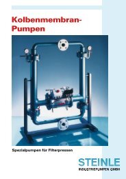
5.1 Capacity curves<br />
The performance curves are based on water at 20°C.Other circumstances might change the performance.<br />
See page chapter 5.2 how the capacity will change at different viscosities and suction<br />
lifts.<br />
HEAD<br />
PSIG mWC<br />
160<br />
200<br />
160<br />
120<br />
80<br />
40<br />
140<br />
120<br />
100<br />
80<br />
60<br />
40<br />
20<br />
HEAD<br />
PSIG mWC<br />
160<br />
200<br />
160<br />
120<br />
80<br />
40<br />
140<br />
120<br />
100<br />
80<br />
60<br />
40<br />
20<br />
0<br />
0<br />
TF50<br />
8<br />
6<br />
4<br />
2<br />
0,2<br />
0,4<br />
TF200<br />
6<br />
4<br />
2<br />
0,8<br />
10<br />
50<br />
20<br />
Instruction manual TF PE & PTFE series pumps 24<br />
0,7<br />
Air pressure (bar)<br />
Air consumption (Nm 3 /min)<br />
l/min<br />
USGPM<br />
CAPACITY<br />
0 2 4 6 8 10 12 14 16 m<br />
CAPACITY<br />
3 /h<br />
5.2 Capacity changes<br />
1,3<br />
1,8<br />
Air pressure (bar)<br />
Air consumption (Nm 3 /min)<br />
100 150 200 250 300 l/min<br />
30 40 50 60 70 USGPM<br />
HEAD<br />
PSIG mWC<br />
160<br />
200<br />
160<br />
120<br />
80<br />
40<br />
140<br />
120<br />
100<br />
80<br />
60<br />
40<br />
20<br />
HEAD<br />
PSIG mWC<br />
160<br />
200<br />
160<br />
120<br />
80<br />
40<br />
140<br />
120<br />
100<br />
80<br />
60<br />
40<br />
20<br />
0<br />
0<br />
0<br />
TF100<br />
8<br />
0,4<br />
6<br />
4<br />
2<br />
1,3<br />
6<br />
4<br />
2<br />
20 40<br />
5<br />
0,8<br />
10<br />
1,2<br />
Air pressure (bar)<br />
Air consumption (Nm 3 /min)<br />
60 80 100 120 140 l/min<br />
15 20 25 30 35 USGPM<br />
1 2 3 4 5 6 7 8 m<br />
CAPACITY<br />
3 /h<br />
TF400<br />
2,0<br />
2,7<br />
3,4<br />
Air pressure (bar)<br />
Air consumption (Nm 3 /min)<br />
100 200 300 400 500 600 l/min<br />
20 40 60 80 100 120 140 USGPM<br />
0 4 8 12 16 20 24 28 32 m<br />
CAPACITY<br />
3 /h<br />
Capacity changes at different suction lifts Capacity changes at different viscosities
5. DATA<br />
5.3 Dimensions<br />
Dimensions in mm (where other is not indicated)<br />
Dimensions in inch (where other is not indicated)<br />
Dim Pump size<br />
50 100 200 400<br />
A2 150 300 300 404<br />
5.91 11.81 11.81 15.91<br />
B2 168 221 320 390<br />
6.61 8.70 12.60 15.35<br />
B3 277 391 490 598<br />
10.91 15.39 19.29 23.54<br />
D3 385 550 700 770<br />
15.16 21.65 27.56 30.31<br />
D4 343 477 630 690<br />
13.50 18.78 24.80 27.17<br />
E3 250 333 467 588<br />
9.84 13.11 18.39 23.15<br />
G 17 30 30 30<br />
0.67 1.18 1.18 1.18<br />
H2 19 33 35 35<br />
0.75 1.30 1.38 1.38<br />
J 1/2” 1” 1 1/2” 2”<br />
1/2 1 1 1/2 2<br />
K M8x25 M8x25 M8x25 M8x25<br />
M8 M8 M8 M8<br />
Instruction manual TF PE & PTFE series pumps 25<br />
General dimensions only, ask us for detailed drawings. Changes reserved without notice
5. DATA<br />
5.4 Technical data<br />
5.5 Tightening torques<br />
The following tightening torques are recommended.<br />
Pump size Mounting torque (Nm)<br />
TF50 8<br />
TF100 16<br />
TF200 20<br />
TF400 23<br />
Instruction manual TF PE & PTFE series pumps 26<br />
TF50 TF100 TF200 TF400<br />
Connections (BSP) 1/2" 1" 1 1/2" 2"<br />
Max suction lift dry (m) 2 2.6 3 3<br />
Max suction lift wet (m) 8 8 8 8<br />
Max air feed pressure (bar) 8 8 6 6<br />
Max discharge pressure (bar) 16 16 12 12<br />
Temperature max PE pumps (°C) 70 70 70 70<br />
Temperature max PTFE pumps (°C) 100 100 100 100<br />
Weight PE pumps (kg) 6 12 27 49<br />
Weight PTFE pumps (kg) 8 19 47 95
6. WARRANTY & REPAIR<br />
6.1 Returning parts<br />
When returning parts to Tapflo AB please follow this procedure:<br />
- Consult Tapflo AB for shipping instructions.<br />
- Cleanse or neutralize and rinse the part/pump. Make sure the part/pump is completely empty<br />
from liquid.<br />
- Pack the return articles carefully to prevent any damage under transport.<br />
Goods will not be accepted unless the above procedure has been complied with.<br />
6.2 Warranty<br />
Tapflo warrants products under conditions as below for a period <strong>of</strong> not more than 12 months from<br />
installation and not more than 24 months from date <strong>of</strong> manufacture.<br />
1. The following terms and condition apply to the sale <strong>of</strong> machinery, components and related<br />
services and products, <strong>of</strong> Tapflo (hereinafter “the products”)<br />
2. Tapflo (the manufacturer) warrants that:<br />
a.) its products as being free <strong>of</strong> defects in material, design and workmanship at the time <strong>of</strong> original<br />
purchase;<br />
b.) its products will function in accordance with Tapflo operative manuals; Tapflo does not guarantee<br />
that the product will meet the precise needs <strong>of</strong> the Customer, except for those purposes<br />
set out in any invitation to render documents or other documents specifically made available<br />
to Tapflo before entering into this agreement;<br />
c.) high quality materials are used in the construction <strong>of</strong> the pumps and that machining and assembly<br />
are carried out to the highest standards.<br />
Except as expressly stated above, Tapflo makes no warranties, express or implied, concerning<br />
the products, including all warranties <strong>of</strong> fitness for a particular purpose.<br />
3. This warranty shall not be applicable in circumstances other than defects in material, design,<br />
and workmanship. In particular warranty shall not cover the following:<br />
a.) Periodic checks, maintenance, repair and replacement <strong>of</strong> parts due to normal wear and tear<br />
(seals, O-rings, rubber items, bushings, etc..);<br />
b.) Damage to the product resulting from:<br />
b.1.) Tampering with, abuse or misuse, including but not limited to failure to use the product for its<br />
normal purposes as stated at the time <strong>of</strong> purchase or in accordance withTapflo instructions<br />
for use and maintenance <strong>of</strong> the product, or the installation or improper ventilation or use <strong>of</strong><br />
the product in a manner inconsistent with the technical or safety standard in force;<br />
b.2.) Repairs performed by non skilled personell or use <strong>of</strong> non original Tapflo parts<br />
b.3.) Accidents or any cause beyond the control <strong>of</strong> Tapflo, including but not limited to lightning,<br />
water, fire, earthquake, and public disturbances, etc.;<br />
4 The warrantee shall cover the replacement or repairing <strong>of</strong> any parts, which is documentedly<br />
faulty due to construction or assembling, with new or repaired parts free <strong>of</strong> charges delivered<br />
by Tapflo. Parts subjected to normal tear and wear shall not be covered by the warranty.<br />
Tapflo shall decide as to whether the defective or faulty part shall be replaced or repaired.<br />
5 The warrantee <strong>of</strong> the products shall be valid for a period in accordance to the current law<br />
from the date <strong>of</strong> delivery, under the condition that notice <strong>of</strong> the alleged defect to the products<br />
or parts there<strong>of</strong> be given to Tapflo in written within the mandatory term <strong>of</strong> 8 days from the<br />
discovery.<br />
Instruction manual TF PE & PTFE series pumps 27
6. WARRANTY & REPAIR<br />
6 Repair or replacement under the terms <strong>of</strong> this warranty shall not give a right to an extension<br />
to, or a new commencement <strong>of</strong>, the period <strong>of</strong> warranty. Repair or replacement under the<br />
terms <strong>of</strong> this warranty may be fulfilled with functionally equivalent reconditioned units. Tapflo<br />
qualified personnel shall be solely entitled to carry out repair or replacement <strong>of</strong> faulty parts<br />
after careful examination <strong>of</strong> the pump. Replaced faulty parts or components will become the<br />
property <strong>of</strong> Tapflo<br />
7 The products are built in accordance with standard CE normative and are tested (where applicable)<br />
by Tapflo. Approval and tests by other control authority are for the customers account.<br />
The products shall not be considered defective in materials, design or workmanship if they<br />
need to be adapted, changed or adjusted to conform to national or local technical or safety<br />
standards in force in any country other than that for which the unit was originally designed and<br />
manufactured. This warranty shall not reimburse such adaptations, changes or adjustments,<br />
or attempt to do so, whether properly performed or not, nor any damage resulting from them,<br />
nor any adaptation, change or adjustments to upgrade the products from their normal purpose<br />
as described in the products operative manual without the prior written consent <strong>of</strong> Tapflo<br />
8 Installation, including electric and other connections to utility mains according to Tapflo drawings,<br />
is for the cost and responsibility <strong>of</strong> the customer, unless otherwise agreed in writing.<br />
9 Tapflo will not be liable on any claim, whether in contact, tort, or otherwise, for any indirect,<br />
special, incidental, or consequential damages, caused to the customer or to third parties, including<br />
loss <strong>of</strong> pr<strong>of</strong>its, arising by any possible infringement <strong>of</strong> par. 3 above or by the customer<br />
or third parties being in the impossibility <strong>of</strong> using the products.<br />
Steady the above,Tapflo liability to the customer or third parties from any claim, whether in contract,<br />
tort, or otherwise, shall be limited to the total amount paid by the customer for the product<br />
that caused the damages.<br />
Instruction manual TF PE & PTFE series pumps 28
6. WARRANTY & REPAIR<br />
6.3 Warranty form<br />
Company:<br />
Telephone: Fax:<br />
Address:<br />
Country: Contact name:<br />
E-mail:<br />
Delivery date: Pump was installed (date):<br />
Pump type: Serial No (stamped on the pump housing):<br />
Description <strong>of</strong> the fault:<br />
The installation<br />
Liquid:<br />
Temperature (°C): Viscosity (cPs): Spec. grav. (kg/m 3 ): pH-value:<br />
Contents <strong>of</strong> particles: %, <strong>of</strong> max size (mm):<br />
Flow (l/min): Duty (h/day): No <strong>of</strong> starts per day:<br />
Discharge head (mwc): Suction head/lift (m):<br />
Air pressure (bar): Quality <strong>of</strong> the air (filter, micron?, lubrication?):<br />
Other:<br />
Place for sketch <strong>of</strong> the installation<br />
Instruction manual TF PE & PTFE series pumps 29
DISTRIBUTOR:<br />
Tapflo AB · Filaregatan 4 · S-442 34 Kungälv · Sweden<br />
Tel (46) 303 63390 · Fax (46) 303 19916 · E-mail: sales@tapflo.com · www.tapflo.com<br />
All data in this instruction manual are based on the latest product information available at the time <strong>of</strong> publication. Changes reserved without notice.
<strong>EC</strong> <strong>declaration</strong> <strong>of</strong> <strong>conformity</strong><br />
Directive 94/9/<strong>EC</strong> (ATEX 100a)<br />
Tapflo AB declares that the following equipment:<br />
Product name: Conductive air operated diaphragm pumps<br />
Models: TX…<br />
Pump material: Conductive PE<br />
Conductive PTFE<br />
Aluminium<br />
Cast iron<br />
Stainless steel AISI 316/316L<br />
Hastelloy C<br />
Diaphragm material: PTFE (conductive)<br />
EPDM (conductive)<br />
NBR<br />
are intended for operation in potentially explosive atmospheres<br />
according to:<br />
Equipment Group: IIG (Gas) / IID (Dust)<br />
Category: 2<br />
Apparatus group: IIB<br />
Temperature class: T4 (other temperature classes on request)<br />
The above equipment comply with the harmonised standards EN 13463-<br />
1 (Non-electrical equipment for potentially explosive atmospheres)<br />
and EN 1127-1 (Explosive atmospheres – Explosion prevention and<br />
protection).<br />
Technical file reference: 03 ATEX S001<br />
Manufacturer: Tapflo AB<br />
Address: Filaregatan 4<br />
S-442 34 Kungälv<br />
Sweden<br />
Tapflo AB, June 1st, 2008<br />
Håkan Ekstrand<br />
Managing director<br />
Tapflo AB Phone Fax Website<br />
Filaregatan 4 +46 303 63390 +46 303 19916 www.tapflo.com<br />
S-442 34 Kungälv, Sweden
<strong>EC</strong> <strong>declaration</strong> <strong>of</strong> <strong>conformity</strong><br />
Directive 94/9/<strong>EC</strong> (ATEX 100a)<br />
Tapflo AB declares that the following equipment:<br />
Product name: Conductive pulsation dampener<br />
Models: PDX…<br />
Dampener material: Conductive PE<br />
Conductive PTFE<br />
Aluminium<br />
Cast iron<br />
Stainless steel AISI 316/316L<br />
Hastelloy C<br />
Diaphragm material: PTFE (conductive)<br />
EPDM (conductive)<br />
NBR (conductive)<br />
are intended for operation in potentially explosive atmospheres<br />
according to:<br />
Equipment Group: IIG (Gas) / IID (Dust)<br />
Category: 2<br />
Apparatus group: IIB<br />
Temperature class: T4 (other temperature classes on request)<br />
The above equipment comply with the harmonised standards EN 13463-<br />
1 (Non-electrical equipment for potentially explosive atmospheres)<br />
and EN 1127-1 (Explosive atmospheres – Explosion prevention and<br />
protection).<br />
Technical file reference: 03 ATEX S001<br />
Manufacturer: Tapflo AB<br />
Address: Filaregatan 4<br />
S-442 34 Kungälv<br />
Sweden<br />
Tapflo AB, June 1st, 2008<br />
Håkan Ekstrand<br />
Managing director<br />
Tapflo AB Phone Fax Website<br />
Filaregatan 4 +46 303 63390 +46 303 19916 www.tapflo.com<br />
S-442 34 Kungälv, Sweden