Ultrasonic friction power during Al wire wedge-wedge bonding
Ultrasonic friction power during Al wire wedge-wedge bonding
Ultrasonic friction power during Al wire wedge-wedge bonding

You also want an ePaper? Increase the reach of your titles
YUMPU automatically turns print PDFs into web optimized ePapers that Google loves.
JOURNAL OF APPLIED PHYSICS 106, 013503 2009<strong>Ultrasonic</strong> <strong>friction</strong> <strong>power</strong> <strong>during</strong> <strong>Al</strong> <strong>wire</strong> <strong>wedge</strong>-<strong>wedge</strong> <strong>bonding</strong>A. Shah, 1,a H. Gaul, 2 M. Schneider-Ramelow, 3 H. Reichl, 2 M. Mayer, 1 and Y. Zhou 11 Microjoining Laboratory, University of Waterloo, Ontario, N2L 3G1, Canada2 Forschungsschwerpunkt Technologien der Mikroperipherik, TU Berlin, Berlin 10623, Germany3 Fraunhofer Institut für Zuverlässigkeit und Mikrointegration (IZM), Berlin 13355, GermanyReceived 1 May 2009; accepted 27 May 2009; published online 1 July 2009<strong>Al</strong> <strong>wire</strong> <strong>bonding</strong>, also called ultrasonic <strong>wedge</strong>-<strong>wedge</strong> <strong>bonding</strong>, is a microwelding process usedextensively in the microelectronics industry for interconnections to integrated circuits. The <strong>bonding</strong><strong>wire</strong> used is a 25 m diameter <strong>Al</strong>Si1 <strong>wire</strong>. A <strong>friction</strong> <strong>power</strong> model is used to derive the ultrasonic<strong>friction</strong> <strong>power</strong> <strong>during</strong> <strong>Al</strong> <strong>wire</strong> <strong>bonding</strong>. Auxiliary measurements include the current delivered to theultrasonic transducer, the vibration amplitude of the <strong>bonding</strong> tool tip in free air, and the ultrasonicforce acting on the <strong>bonding</strong> pad <strong>during</strong> the bond process. The ultrasonic force measurement is likea signature of the bond as it allows for a detailed insight into mechanisms <strong>during</strong> various phases ofthe process. It is measured using piezoresistive force microsensors integrated close to the <strong>Al</strong><strong>bonding</strong> pad <strong>Al</strong>–<strong>Al</strong> process on a custom made test chip. A clear break-off in the force signal isobserved, which is followed by a relatively constant force for a short duration. A large secondharmonic content is observed, describing a nonsymmetric deviation of the signal wave form fromthe sinusoidal shape. This deviation might be due to the reduced geometrical symmetry of the <strong>wedge</strong>tool. For bonds made with typical process parameters, several characteristic values used in the<strong>friction</strong> <strong>power</strong> model are determined. The ultrasonic compliance of the <strong>bonding</strong> system is2.66 m/N. A typical maximum value of the relative interfacial amplitude of ultrasonic <strong>friction</strong> isat least 222 nm. The maximum interfacial <strong>friction</strong> <strong>power</strong> is at least 11.5 mW, which is only about4.8% of the total electrical <strong>power</strong> delivered to the ultrasonic generator. © 2009 American Instituteof Physics. DOI: 10.1063/1.3158065I. INTRODUCTION<strong>Ultrasonic</strong> <strong>wire</strong> <strong>bonding</strong> is widely used in microelectronicspackaging to make interconnections between the integratedcircuit chip and the package metallization. 1 It is asolid state welding process in which a thin <strong>wire</strong> is welded toa metallized surface using a combination of normal force andultrasonic energy. However, despite being a widely acceptedprocess in industry, there is a general lack of understandingof the <strong>bonding</strong> mechanisms in ultrasonic <strong>wire</strong> <strong>bonding</strong>. Acomplete quantitative model of the <strong>wire</strong> <strong>bonding</strong> processdoes not exists. 1Several investigations have been performed to understandthe physics of the <strong>wire</strong> <strong>bonding</strong> process. 2–10 In additionto the conventional offline process monitoring methods suchas visual inspection, <strong>wire</strong> pull testing, and bond shear testing,novel real-time monitoring techniques such as the measurementsof ultrasound amplitudes using laser interferometry, 11piezoelectric sensor attached to the horn, 12 piezoelectric sensormounted to the heater block, 13 and integrated piezoresistivemicrosensors 14–25 have been applied to gain a better understandingof the process mechanisms.The Au <strong>wire</strong> ball <strong>bonding</strong> on <strong>Al</strong> pads was studied indetail using integrated piezoresistive microsensors to measurethe in situ forces caused by the ultrasound induced tothe pad. 14–17 Based on the first and third harmonics of therecorded ultrasonic signal, five bond phases are distinguished<strong>during</strong> the process. The third harmonic of the ultrasonic forcea Electonic mail: ashah011@engmail.uwaterloo.ca.signal was used to explain two <strong>friction</strong> processes: ultrasonicstick-slip <strong>friction</strong> between the Au ball and <strong>Al</strong> pad before and<strong>during</strong> bond formation and <strong>friction</strong> between ball and capillaryafter bond formation. 16,17 It was concluded that the relativestick-slip motion between the ball and the pad produceswear, which is a prerequisite for high quality Au ball <strong>bonding</strong>on <strong>Al</strong> pads.The concept of stick-slip <strong>friction</strong> was further developedin Refs. 18 and 19. A <strong>friction</strong> <strong>power</strong> model was formulatedbased on Amontons laws of <strong>friction</strong> to calculate the <strong>friction</strong><strong>power</strong> delivered to the bond. In Ref. 20, a bond quality factorwas introduced based on <strong>friction</strong> <strong>power</strong>. This model was extendedin Ref. 11 to include <strong>wire</strong> deformation <strong>during</strong> theprocess.In Ref. 21, the microsensor method was applied to studythe Cu–<strong>Al</strong> ball <strong>bonding</strong> process. It was concluded that althoughreduced in relative magnitude compared to the Au–<strong>Al</strong>process, the amount of stick-slip <strong>friction</strong> in Cu–<strong>Al</strong> process isstill an important mechanism for a successful Cu ball <strong>bonding</strong>on <strong>Al</strong> pads.In this paper, a study of in situ ultrasonic force signals ofan <strong>Al</strong> <strong>wedge</strong> <strong>bonding</strong> process on <strong>Al</strong> pads is reported. <strong>Al</strong><strong>wedge</strong> bonds are investigated for the same or similar mechanismsobserved previously <strong>during</strong> Au–<strong>Al</strong> ball <strong>bonding</strong> processes.In combination with measurements of the currentsupplied to the ultrasonic transducer and free-air vibrationamplitude of the tool tip, the measured ultrasonic force isused to derive the ultrasonic <strong>friction</strong> <strong>power</strong> <strong>during</strong> the <strong>Al</strong>–<strong>Al</strong><strong>wedge</strong> <strong>bonding</strong> process.0021-8979/2009/1061/013503/8/$25.00106, 013503-1© 2009 American Institute of PhysicsAuthor complimentary copy. Redistribution subject to AIP license or copyright, see http://jap.aip.org/jap/copyright.jsp
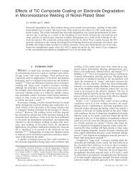
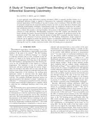
013503-3 Shah et al. J. Appl. Phys. 106, 013503 2009TABLE I. USP profile for calibration experiment.Segment numberImpact force=1000 mN Bond force=1000 mN1 2 1 2 3 4 5 6 7 8Time ms 1 1 10 10 10 10 10 10 10 10Ultrasound % 0 0 2 4 6 8 10 12 14 16bration factor of the microsensor is evaluated as the slope ofthe linear fit in Fig. 4b and is determined to be f calib=5.90.33 mV/V N. The error value includes the fit errorand the sensitivity error of the standard sensor. Thus, theultrasonic force measured using the microsensor isF T t = St .1f calibB. Experimental plan<strong>Al</strong> <strong>wire</strong> <strong>wedge</strong> <strong>bonding</strong> is performed on the <strong>Al</strong> test padof the microsensor and the in situ ultrasonic force variations<strong>during</strong> the <strong>bonding</strong> process is measured simultaneously Thefirst bond is performed on the microsensor test pad and thesecond bond is made on the package rim as shown in Fig.5a. An example <strong>wedge</strong> bond on the microsensor test pad isshown in Fig. 5b. The parameters used for <strong>bonding</strong> areshown in Table II. Note the different USP used compared tothat previously described for the ball bonder. The technicalUSP of the <strong>wedge</strong> bonder is dimensionless and ranges from 0to 200 units. To relate it to a physical quantity, the transientfree-air vibration amplitude of the tool tip, A 0 t, is measuredusing a Laser Interferometer OFV 501 and a VibrometerController OFV 3000 of Polytec GmbH, Waldbronn, GermanyA laser spot of 6 m in diameter is focused at thecenter of the tool tip while vibrating freely in air F N =0, no<strong>wire</strong> for USP=100 units. A typical plot of A 0 t is shown inFig. 6, resulting in a maximum vibration amplitude, A 0max=0.75 m. The result shows that there is 6.5 ms time lagto reach 95% of A 0 max .C. Results and discussion1. <strong>Ultrasonic</strong> force signalAn example ultrasonic force signal is shown in Fig. 7a.The signal consists of approximately 3500 cycles of ultrasonicvibrations. As soon as the ultrasonic period starts, F Trises sharply for approximately 2.5 ms when a break-off inthe signal is observed. About 1.5 ms after the break-off, thesignal starts to rise gradually until the end of the ultrasonicperiod. The waveforms of the signal at various times areshown in Fig. 7b. It is found that immediately after thebreak-off, the signal waveform 3 and 6 ms in Fig. 7bdeviates from the sinusoidal shape it had initially at 1 ms.This deviation is observed in only one direction of the ultrasoniccycle, i.e., when the F T rises from the negative halfcycle to the positive half cycle. The waveform returns tosinusoidal shape about 10 ms after the break-off. In contrast,the break-off reported previously in Au <strong>wire</strong> ball <strong>bonding</strong> on<strong>Al</strong> pads 14 is characterized by a cropped sinusoidal waveform.The ultrasonic force signal is filtered at its fundamentaland second and third harmonic frequencies and the resultingamplitudes are plotted in Fig. 8. Amplitudes of harmonicshigher than the third are negligible and hence not shown.Four phases 1–4 can be distinguished for the <strong>Al</strong>–<strong>Al</strong> process.During phase 1, the <strong>wire</strong> sticks to the pad. This isbecause A 0 t is not high enough to overcome the static <strong>friction</strong>alforce F b required to cause any sliding at the interface.Phase 2 starts at time t b when the fundamental firstharmonic of F T shows the characteristic break-off. At thesame time, the second and third harmonics start to increasesharply from zero. This is caused by the onset of <strong>friction</strong> atthe <strong>wire</strong>-pad interface. The <strong>friction</strong> facilitates the relativesliding of the <strong>wire</strong> on the pad causing bond area cleaning byFIG. 4. a Example microsensor response for calibration test. Numbers in % indicate ultrasound level; b Calibration curve with step values from tests.Author complimentary copy. Redistribution subject to AIP license or copyright, see http://jap.aip.org/jap/copyright.jsp
013503-4 Shah et al. J. Appl. Phys. 106, 013503 2009FIG. 6. Free-air vibration amplitude of tool tip A 0 t for USP=100 units.FIG. 5. Color online a Overview photograph showing <strong>Al</strong> <strong>wire</strong> <strong>wedge</strong>bonds on microsensor chip; b closeup of example <strong>wedge</strong> first bond onmicrosensor test pad.wear of the native oxide layers at the interface. Moreover,the first harmonic does not rise any further until the end ofthis phase at t b2 , indicating the need of “minimum cleaning”or minimum amount of <strong>friction</strong> work wear to accumulatebefore the native oxide layers are sufficiently removed fromthe interface to allow the formation of bonded areas.The cleaning continues and is accompanied by <strong>bonding</strong><strong>during</strong> phase 3 when the first harmonic of the ultrasonicforce signal starts to rise again. Bonding is expressed by theformation of welded areas at the interface that grow largerwhere the metals at opposite sides have been sufficientlycleaned. The sum of all bonded areas is the effective bondedarea, 11 which is growing due to the <strong>friction</strong> <strong>power</strong> that continuesto clean the interface. During phase 4, the fundamentaland harmonics of the ultrasonic force signal remain relativelyconstant. It is believed that <strong>bonding</strong> action has endedat the onset of this phase and ultrasonic <strong>friction</strong> <strong>power</strong> mightnot aid in any further <strong>bonding</strong>.FIG. 7. a In situ ultrasonic force signal of <strong>Al</strong>–<strong>Al</strong> <strong>wedge</strong> <strong>bonding</strong> process;b Signal waveforms at different times after ultrasound on.2. Second harmonicIn contrast to any ball <strong>bonding</strong> process, the second harmonicamplitude of the ultrasonic force signal is found to bepredominant <strong>during</strong> the <strong>Al</strong>–<strong>Al</strong> <strong>wedge</strong> <strong>bonding</strong> process. Thisis consistent to the previously reported studies involvingmeasurement of ultrasonic amplitude <strong>during</strong> <strong>Al</strong>–<strong>Al</strong> <strong>wedge</strong>TABLE II. Optimized <strong>wedge</strong> bond parameters.Parameter<strong>Ultrasonic</strong> parameter USPBond force F NTouchdown forceTimeValue100 units250 mN50 mN35 msFIG. 8. Color online Amplitudes of harmonics of ultrasonic force signal of<strong>Al</strong>–<strong>Al</strong> <strong>wedge</strong> <strong>bonding</strong> process shown in Fig. 7a.Author complimentary copy. Redistribution subject to AIP license or copyright, see http://jap.aip.org/jap/copyright.jsp
013503-5 Shah et al. J. Appl. Phys. 106, 013503 2009FIG. 11. Flow diagram outlining the procedure to derive Pt.Pt =4·f · A rel t · F T t, 2where f =95 kHz is the ultrasonic frequency and A rel t is theamplitude zero-to-peak of relative motion between the <strong>wire</strong>and the pad. To derive experimental values for Pt, a numberof evaluation steps are necessary, which are outlined inFig. 11. The amplitude of relative motion, A rel t, is derivedFIG. 9. Color online Illustrations of ultrasonic vibrational symmetry of a using a simplified model describing the interfacial <strong>friction</strong>ball bond process symmetry and b <strong>wedge</strong> bond process reduced <strong>during</strong> the <strong>wire</strong> <strong>bonding</strong> process. The current supplied to thesymmetry.ultrasonic transducer <strong>during</strong> the <strong>bonding</strong> process measuredsimultaneously with F<strong>bonding</strong> process using piezoelectric sensors attached to theT t is used to derive a free-airhorn 12 and to the heater block. 13 equivalent of ultrasonic vibration amplitude <strong>during</strong> the <strong>bonding</strong>process, AThis may be attributed to thereduced geometrical symmetry of the <strong>wire</strong> and the <strong>wedge</strong>B t. The value of A B t is then used to deriveAtool Fig. 9b, possibly causing the different vibration rel t. <strong>Al</strong>l the formulas associated with this derivation aredescribed in the subsections that follow.shapes for positive compared to negative half cycles as observedin the 3, 6, and 9 ms signal waveforms in Fig. 7b. Inparticular, the geometry of the tool tip shown in Fig. 10 isnot symmetrical since the tip radii at the left and right sides A. Free-air equivalent of ultrasonic vibrationare 25 and 15 m, respectively. In contrast, the rotational amplitudesymmetries of the ball and the capillary geometry illustrated The ultrasonic vibrations are generated by a piezoelectrictransducer. During the free-air vibration, the transducerin Fig. 9a result in identical ultrasonic vibrations for bothpositive and negative half cycles <strong>during</strong> ball <strong>bonding</strong>. current It is proportional to A 0 t,III. ULTRASONIC FRICTION POWERk 1 = ItThe ultrasonic <strong>friction</strong> <strong>power</strong> delivered at the interfaceA 0 t = Imaxmax 0.19 0.01 A/m,A 30<strong>during</strong> the <strong>bonding</strong> process can be derived from the measuredF T t using 19 where k 1 is the constant of proportionality and I max is themaximum value of current supplied to the generator in thefree-air vibration case FVC.However, <strong>during</strong> the actual <strong>bonding</strong> process, the normalforce F N presses the <strong>wire</strong> to the pad. Friction dynamic orstatic dampens the vibration amplitude as seen by less currentgoing to the transducer <strong>during</strong> the <strong>bonding</strong> process caseBPC as compared to the FVC shown in Fig. 12a. Thetransducer current measured <strong>during</strong> BPC is I B t and is usedto define the free-air equivalent of the ultrasonic vibrationamplitude <strong>during</strong> the <strong>bonding</strong> process,A B t = I Bt. 4k 1FIG. 10. Illustration of <strong>wedge</strong> tool tip.An example plot of A B t is shown in Fig. 12b.Author complimentary copy. Redistribution subject to AIP license or copyright, see http://jap.aip.org/jap/copyright.jsp
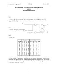
013503-6 Shah et al. J. Appl. Phys. 106, 013503 2009FIG. 12. Color online a Transducer current and b amplitude <strong>during</strong>FVC USP=100 units and F N =0 and BPC USP=100 units and F N=150 mN. I 0 t, I B t, A 0 t are measured characteristics. A B t derived usingEq. 4.B. Amplitude of relative motionInterfacial welding in BPC is generated by the ultrasonic<strong>friction</strong>. During ultrasonic <strong>friction</strong>, F T t is acting at the<strong>wire</strong>-pad interface. The ultrasound causes both the <strong>wire</strong> andthe pad to vibrate at the interface. The vibration amplitudesof the <strong>wire</strong> bottom and pad top are denoted as a w t anda p t, respectively, as illustrated in Fig. 13. The relative motionbetween the <strong>wire</strong> and the pad isA rel t = a w t − a p t.5In the case where there is no relative motion between the<strong>wire</strong> and pad,A rel t =0.6In the case where the <strong>wire</strong> is vibrating with the tool in freeair i.e., F N =0,a w t = A B t, a p t = 0, and F T t =0. 7The amplitudes a w t and a p t can be described as functionsof F T t using Eqs. 6 and 7, and the linear model shownin Fig. 14. In this model, it is assumed that the amplitudesa w t and a p t vary linearly with F T t. Thus,a w t = A B t − c w · F T t8anda p t = c p · F T t,where c w and c p are the ultrasonic compliances inverse stiffnessesof the <strong>wire</strong>/tool and pad/chip, respectively.FIG. 13. Color online Illustration of the vibration amplitudes at the <strong>wire</strong>padinterface <strong>during</strong> BPC.9FIG. 14. Color online A simplified model of the <strong>friction</strong> process <strong>during</strong> theultrasonic <strong>wire</strong> <strong>bonding</strong> process.Using Eqs. 5, 6, 8, and 9, the amplitude of relativemotion is= A rel t 0for 0 t t b10A B t − c · F T t for t t b ,where c=c w +c p is the total ultrasonic compliance of the<strong>bonding</strong> system.The relative motion between the <strong>wire</strong> and pad starts atthe transition point T Fig. 14, marking the transition from“no sliding” to “sliding.” Point T corresponds to the breakoffpoint observed in the ultrasonic force signal Fig. 7a.Atypical maximum value for A rel t is 22216 nm.It may seem counterintuitive that A rel decreases while F Tincreases Fig. 14. However, F T is not one of the processparameters that can be controlled, e.g., via USP. It is affectedby F N and by the bond growth at the interface. A highervalue of F N will lead to a higher value of F T for <strong>friction</strong> atthe interface, thereby “damping” A rel . Similarly, bond growthat the interface reduces A rel , while F T may still rise.C. <strong>Ultrasonic</strong> complianceAt point T, A rel t b =0 and with Eq. 10,c = A Bt b F T t b = a b,11F bwhere a b is the ultrasonic amplitude marking the transitionbetween sliding and no sliding. The values a b=0.370.04 m and F b =1377.30 N are visually estimatedfrom Figs. 12b and 8, respectively. Using Eq. 11,the value of the compliance is c=2.660.18 m/N.D. Results and discussionAn example plot of Pt evaluated using Eq. 2, averagedover ten bonds, is shown in Fig. 15. The <strong>friction</strong> <strong>power</strong>Pt emerges from zero at t b and increases rapidly until itreaches a maximum value P max , about 6 ms after ultrasoundon. Then it starts to decrease. This decrease is due tobond growth, which reduces the relative motion between the<strong>wire</strong> and pad. However, the derivation of Pt using Eq. 2is not valid after the end of phase 2, since the linearity as-Author complimentary copy. Redistribution subject to AIP license or copyright, see http://jap.aip.org/jap/copyright.jsp
013503-7 Shah et al. J. Appl. Phys. 106, 013503 2009IV. CONCLUSIONSFIG. 15. Color online <strong>Ultrasonic</strong> <strong>friction</strong> <strong>power</strong> Pt. Phases as in Fig. 8.sumption of a w t and a p t is no longer valid. The Pt curvederived after the end of phase 2 indicated using dashedlines is based on the assumption that value of c remainssame as calculated at t b1 .However, beyond time t b2 , the <strong>bonding</strong> action starts, resultingin two physical mechanisms contributing to the nonlinearityof the model. First, the cleaning process removesthe native oxide layers from the <strong>wire</strong> and pad, bringing twoclean metal layers in contact with each other. This can beinterpreted as a transient change in the coefficient of <strong>friction</strong>at the interface from s to m with m s , where s is thecoefficient of <strong>friction</strong> between the two oxide surfaces and mis the coefficient of <strong>friction</strong> between the cleaned metal surfaces.The second mechanism is the plastic deformation ofthe <strong>wire</strong> <strong>during</strong> the ultrasonic period. This leads to a flatteningof the <strong>wire</strong> and therefore to a reduction in the value of c<strong>during</strong> <strong>bonding</strong>. Other reasons might be changes in <strong>wire</strong> materialproperties such as hardness <strong>during</strong> <strong>bonding</strong>. 23 Whilethe changes in the coefficient of <strong>friction</strong> is already includedin the model as the measured F T t, the effect due to thereduction in the value of c is not quantified. A reduction inthe value of c causes an increase in A rel t Eq. 10, andthus leads to an increase in Pt Eq. 2. For example, thePt curve derived for c reduced by 10% is shown in Fig. 15.The total <strong>power</strong> supplied to the ultrasonic transducer, P Tis calculated usingP T = V Bmax · I B max = 238 6mW,12where V B max and I B max are the maximum peak-to-peak valuesof voltage and current supplied to the ultrasonic generator<strong>during</strong> BPC, respectively. The maximum <strong>friction</strong> <strong>power</strong> isP max =11.50.7 mW, i.e., only about 4.8% of the total electrical<strong>power</strong> delivered to the ultrasonic transducer ends up atthe bond interface. The remaining <strong>power</strong> supplied to thetransducer is lost due to either internal <strong>friction</strong> damping inthe material or heat dissipation caused by <strong>friction</strong> betweenthe interfaces in the piezoelectric transducer. With an interfacialbond area estimated at 2950 m 2 , the maximum <strong>friction</strong><strong>power</strong> density is 3.9 W/mm 2 . This value is of the sameorder of magnitude as those reported for typical macroscopic<strong>Al</strong>–<strong>Al</strong> ultrasonic welding processes. 23 The value is about2–2.6 times and 1.9 times as high as those reported for atypical Au–<strong>Al</strong> <strong>bonding</strong> process 19 and a Au–SiO 2 <strong>friction</strong>process, 24 respectively.In contrast to previously studied Au ball on <strong>Al</strong> pad <strong>bonding</strong>processes, the ultrasonic force transmitted to the <strong>Al</strong> padin <strong>Al</strong> <strong>wire</strong> <strong>wedge</strong>-<strong>wedge</strong> <strong>bonding</strong> contains a strong asymmetriccomponent. This is expressed by the large amount ofsecond harmonic content found in the force signals. Theother signal features are similar to those of a typical Au ballto <strong>Al</strong> pad <strong>bonding</strong> process, in particular, the typical timerequired to have successful <strong>bonding</strong>.A method to derive the ultrasonic <strong>friction</strong> <strong>power</strong> hasbeen demonstrated for a typical <strong>Al</strong>–<strong>Al</strong> <strong>wedge</strong> <strong>bonding</strong> processand typical <strong>power</strong> values have been calculated. Themethod uses a <strong>friction</strong> <strong>power</strong> theory based on Amontonslaws of <strong>friction</strong> and uses the measured ultrasonic force as aninput. As a side product, the <strong>Al</strong>–<strong>Al</strong> <strong>friction</strong> coefficient hasbeen measured. Other coefficients are determined as neededby the theory, including an ultrasonic compliance of the<strong>bonding</strong> system. For the first time, a maximum relative amplitudeof the ultrasonic <strong>friction</strong> at the interface is reported.In the future, deriving the ultrasonic <strong>friction</strong> <strong>power</strong> willhelp to understand possible interactions between surfacephysics and the joining mechanisms of this process. Thetheory might be extended to predict <strong>bonding</strong> process parametersand bond strength, possibly leading to new controlmethodologies 25 and higher process quality.ACKNOWLEDGMENTSWe wish to acknowledge Oerlikon Esec, Cham, Switzerlandfor providing the microsensor test chip that is used inthis work. This work is supported by Natural Sciences andEngineering Research Council of Canada NSERC, OntarioCenters of Excellence OCE, Government of Canada’s <strong>Al</strong>exanderGraham Bell Canada Graduate Scholarship, andUniversity of Waterloo President’s Graduate Scholarship.1 G. Harman, Wire Bonding in Microelectronics—Materials, Processes, Reliability,and Yield, 2nd ed. McGraw-Hill, New York, 1997.2 G. Harman and K. O. Leedy, Proceedings of the Tenth Annual ReliabilityPhysics Symposium, 1972 unpublished, pp. 49–56.3 G. Harman and J. <strong>Al</strong>bers, IEEE Trans. Parts Hybrids Packag. 13, 4061977.4 K. C. Joshi, Weld. J. Miami, FL, U.S. 50, 840 1971.5 J. E. Krzanowski, IEEE Trans. Compon., Hybrids, Manuf. Technol. 13,176 1990.6 J. L. Harthoorn, Proceedings of the International Conference on <strong>Ultrasonic</strong>s,1973 unpublished, pp. 43–51.7 G. Chen, Proceedings of the International Hybrid Microelectronics Symposium,1972 unpublished.8 N. Zhou, X. Li, and N. J. Noolu, IEEE Trans. Compon. Packag. Technol.28, 810 2005.9 I. Lum, J. P. Jung, and Y. Zhou, Metall. Mater. Trans. A 36A, 12792005.10 I. Lum, M. Mayer, and Y. Zhou, J. Electron. Mater. 35, 4432006.11 H. Gaul, M. Schneider-Ramelow, K.-D. Lang, and H. Reichl, Proceedingsof the First Electronics Systemintegration Technology Conference, 2006unpublished, Vol. 2, pp. 719–725.12 S. W. Or, H. L. W. Chan, V. C. Lo, and C. W. Yuen, Sens. Actuators, A 65,69 1998.13 R. Pufall, Proceedings of the IEEE Electronic Components and TechnologyConference, 1993 unpublished, pp. 159–162.14 M. Mayer, J. Schwizer, O. Paul, D. Bolliger, and H. Baltes, Advances inElectronic Packaging (Proceedings of the InterPACK99 Conference)ASME, New York, 1999, Vol. 26-1, pp. 973–978.15 M. Mayer, “Microelectronic <strong>bonding</strong> process monitoring by integratedsensors,” Ph.D. dissertation, ETH Zurich, 2000.Author complimentary copy. Redistribution subject to AIP license or copyright, see http://jap.aip.org/jap/copyright.jsp
013503-8 Shah et al. J. Appl. Phys. 106, 013503 200916 J. Schwizer, “CMOS force sensors for <strong>wire</strong> <strong>bonding</strong> and flip chip processcharacterization,” Ph.D. dissertation, ETH Zurich, 2003.17 J. Schwizer, M. Mayer, and O. Brand, Force Sensors for MicroelectronicPackaging Applications Springer-Verlag, Berlin, 2005.18 J. Schwizer, M. Mayer, D. Bolliger, O. Paul, and H. Baltes, Proceedings ofthe IEEE/CPMT International Electronics Manufacturing TechnologySymposium, 1999 unpublished, pp. 108–114.19 M. Mayer and J. Schwizer, Proceedings of IMAPS International Symposiumon Microelectronics, 2002 unpublished.20 M. Mayer and J. Schwizer, Proceedings of the IEEE Electronic PackagingTechnology Conference, Singapore, 2003 unpublished, pp. 738–743.21 A. Shah, M. Mayer, Y. Zhou, S. J. Hong, and J. T. Moon, Microelectron.Eng. 85, 1851 2008.22 U. Geissler, M. Schneider-Ramelow, K. Lang, and H. Reichl, J. Electron.Mater. 35, 173 2006.23 X. Cheng and A. Li, J. Micromech. Microeng. 17, 2732007.24 M. Mayer and A. Zwart, Proceedings of THERMEC Conference, 2006unpublished, pp. 3920–3925.25 U. Geissler, H. Reichl, H. Gaul, K.-D. Lang, and M. Schneider-Ramelow,European Patent Application No. WO2008028906 13 March 2008.Author complimentary copy. Redistribution subject to AIP license or copyright, see http://jap.aip.org/jap/copyright.jsp