The Challenges of Building Advanced Mechatronic Systems
The Challenges of Building Advanced Mechatronic Systems
The Challenges of Building Advanced Mechatronic Systems

Create successful ePaper yourself
Turn your PDF publications into a flip-book with our unique Google optimized e-Paper software.
<strong>The</strong> <strong>Challenges</strong> <strong>of</strong> <strong>Building</strong> <strong>Advanced</strong> <strong>Mechatronic</strong> <strong>Systems</strong><br />
Wilhelm Schäfer and Heike Wehrheim<br />
Dr. Wilhelm Schäfer is a pr<strong>of</strong>essor and chair <strong>of</strong> the International<br />
Graduate School <strong>of</strong> Computer Science and Engineering at the<br />
University <strong>of</strong> Paderborn, Germany. Prior appointments have been<br />
with the University <strong>of</strong> Dortmund, Germany and McGill University at<br />
Montreal. He also spent four years in industry as head <strong>of</strong> the R&D<br />
department <strong>of</strong> a medium-size s<strong>of</strong>tware house. His research interests<br />
are in object-oriented specifications for embedded systems, s<strong>of</strong>tware<br />
processes, and re-engineering. He was program co-chair <strong>of</strong> the 23rd<br />
International Conference on S<strong>of</strong>tware Engineering 2001 and program<br />
chair <strong>of</strong> the European S<strong>of</strong>tware Engineering conference 1995. He is<br />
General Chair <strong>of</strong> ICSE 2008 in Leipzig, Germany.<br />
Dr. Heike Wehrheim is a pr<strong>of</strong>essor <strong>of</strong> Computer Science at the<br />
University <strong>of</strong> Paderborn. She obtained her PhD from the University <strong>of</strong><br />
Hildesheim and her habilitation from the University <strong>of</strong> Oldenburg, both<br />
in Germany. Her research interests are in formal methods for the<br />
design <strong>of</strong> correct systems, in particular on specification and<br />
verification techniques. She is a member <strong>of</strong> the IFIP working group<br />
6.1 and was program co-chair <strong>of</strong> its working conference FMOODS in<br />
2006.
<strong>The</strong> <strong>Challenges</strong> <strong>of</strong> <strong>Building</strong> <strong>Advanced</strong> <strong>Mechatronic</strong> <strong>Systems</strong><br />
Abstract<br />
<strong>Mechatronic</strong>s is an engineering discipline integrating<br />
the fields <strong>of</strong> mechanical engineering, electrical engineering<br />
and computer science. While the word ”mechatronics” already<br />
has a long history, it is only the last ten years that<br />
we see their application all around us. Cars, CD players,<br />
washing machines, railways are all examples <strong>of</strong> mechatronic<br />
systems. <strong>The</strong> main characteristic (and driving force)<br />
<strong>of</strong> recent advances is the progressively tighter coupling <strong>of</strong><br />
mechanic and electronic components with s<strong>of</strong>tware. This<br />
makes s<strong>of</strong>tware engineering (together with network technology)<br />
the main computer science discipline involved in<br />
mechatronics.<br />
In this paper we survey current developments and discuss<br />
future trends in mechatronics, in particular from a<br />
s<strong>of</strong>tware engineering point <strong>of</strong> view. <strong>The</strong> future <strong>of</strong> mechatronics<br />
will specifically see a move towards a high degree<br />
<strong>of</strong> adaptibility and self-organisation. This poses new challenges<br />
on s<strong>of</strong>tware engineering, especially on modelling,<br />
code generation and analysis. We exemplify existing as well<br />
as future strands by a collaborative research and development<br />
project <strong>of</strong> a mechatronic rail system from the University<br />
<strong>of</strong> Paderborn.<br />
1. Introduction<br />
<strong>Mechatronic</strong>s is the engineering discipline concerned<br />
with the construction <strong>of</strong> systems incorporating mechanical,<br />
electronical and information technology components. <strong>The</strong><br />
word mechatronics as a blend <strong>of</strong> mechanics and electronics<br />
has already been invented 40 years ago by a japanese company.<br />
<strong>The</strong>n, mechatronics just ment complementing mechanical<br />
parts with some electronical units, a typical representant<br />
being a photo camera. Today, mechatronics is<br />
an area combining a large number <strong>of</strong> advanced techniques<br />
from engineering, in particular sensor and actuator technology,<br />
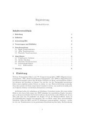
with computer science methods. Figure 1 depicts the<br />
three areas <strong>of</strong> mechatronics and their overlap.<br />
Wilhelm Schäfer and Heike Wehrheim<br />
Institut für Informatik<br />
Universität Paderborn<br />
{wilhelm,wehrheim}@upb.de<br />
Mechanics<br />
S<strong>of</strong>tware<br />
Electronics<br />
<strong>Mechatronic</strong>s<br />
Figure 1. <strong>The</strong> three areas <strong>of</strong> mechatronics<br />
Typical examples <strong>of</strong> mechatronic systems are automotive<br />
applications, e.g. advanced braking systems, fly/steer-bywire<br />
or active suspension techniques, but also DVD-players<br />
or washing machines. <strong>Mechatronic</strong> systems are characterised<br />
by a combination <strong>of</strong> basic mechanical devices with a<br />
processing unit monitoring and controlling it via a number<br />
<strong>of</strong> actuators and sensors (see also Figure 5, Section 3). This<br />
lead to massive improvements in product performance and<br />
flexibility. <strong>The</strong> introduction <strong>of</strong> mechatronics as a tight integration<br />
<strong>of</strong> mechanical, electronical and information-driven<br />
units allowed for turning conventionally designed mechanical<br />
components into smart devices. <strong>The</strong> significance <strong>of</strong><br />
mechatronics is today also reflected in university education:<br />
mechatronics has become a degree on its own, and<br />
is at many places not merely taught by one area but jointly<br />
by all three. <strong>The</strong> subject managed to cross the traditional<br />
boundaries between engineering and computer science.<br />
Today we see the first steps in the emergence <strong>of</strong> the next<br />
generation <strong>of</strong> mechatronic systems. While ”intelligence”<br />
in the behaviour has so far always been achieved by gathering<br />
information (and reacting to it) from the one single<br />
machine, the usage and retrieval <strong>of</strong> information in the future<br />
will be characterised by an exchange <strong>of</strong> information<br />
between different machines. This can for instance already<br />
be seen in the automotive and rail domain: Intelligent lighting<br />
systems combine information about their environment<br />
obtained from their own sensors with those collected by
other cars. In the Paderborn rail system (introduced in more<br />
detail in the next section) shuttles autonomously form convoys<br />
as to reduce air resistance and optimise energy consumption.<br />
This is a general trend: <strong>The</strong> smart devices <strong>of</strong><br />
today’s mechatronic systems will turn into ”populations” <strong>of</strong><br />
smart devices, exchanging information for optimising their<br />
global behaviour as well as possibly competing for limited<br />
resources. This movement imposes in particular new challenges<br />
on the computer science side in mechatronics. <strong>The</strong><br />
mechatronic systems <strong>of</strong> the future will be characterised by<br />
the following properties:<br />
• High degree <strong>of</strong> concurrency: <strong>Systems</strong> will consist <strong>of</strong><br />
a large number <strong>of</strong> autonomous components, exchanging<br />
information while running in parallel. Components<br />
may form cluster to collaborate on a common goal but<br />
may also compete as to optimise their own aims.<br />
• Decentralisation: Due to the high degree <strong>of</strong> concurrency<br />
and distribution systems cannot be centrally observed<br />
and as a consequence not centrally controlled.<br />
• Self-Coordination: As a result <strong>of</strong> the previous two<br />
points, advanced mechatronic systems will largely<br />
have to rely on principles <strong>of</strong> self-coordination.<br />
Several disciplines in computer science are affected by<br />
this change. For achieving reliable and secure transmission<br />
<strong>of</strong> information the areas <strong>of</strong> network technology and cryptography<br />
are challenged. With respect to the issue <strong>of</strong> selfcoordination<br />
it is in particular s<strong>of</strong>tware engineering which<br />
has to make a major step towards a new design methodology.<br />
Current self-* developments in s<strong>of</strong>tware engineering<br />
are already making small steps in this direction. For<br />
the design <strong>of</strong> complex mechatronic systems <strong>of</strong> the future<br />
these have to be combined and complemented with other<br />
advanced techniques as to form an engineering method for<br />
self-coordinating systems. Such a method in particular has<br />
to involve<br />
• new modelling formalisms integrating model transformations<br />
(describing adaptation, reconfiguration etc.)<br />
themselves into the model,<br />
• new code generation techniques, operating at run-time<br />
and taking platform specific parameters into account,<br />
• elaborate formal analysis techniques being able to<br />
cope with the high volatility <strong>of</strong> systems (and properties<br />
emerging by a continous dynamic change).<br />
In addition to the challenges that future mechatronic systems<br />
will bring to s<strong>of</strong>tware engineering, there are also a lot<br />
<strong>of</strong> unsolved issues in the design <strong>of</strong> current systems. While<br />
mechatronic systems indeed incorporate parts constructed<br />
by different engineering disciplines and computer science,<br />
the actual cooperation during the construction is less developed.<br />
<strong>The</strong>re is no joint development process, no joint<br />
tool usage, no joint modelling formalism and no joint analysis.<br />
Every discipline has its own approaches; an integrated<br />
framework for the construction <strong>of</strong> mechatronic systems is<br />
missing.<br />
In the following we will sketch a general architectural<br />
model <strong>of</strong> mechatronic systems, exemplified by a mechatronic<br />
rail system from the University <strong>of</strong> Paderborn. From a<br />
s<strong>of</strong>tware engineering point <strong>of</strong> view we survey current state<br />
<strong>of</strong> the art in the development <strong>of</strong> mechatronic systems. This<br />
especially covers modelling formalisms and tool support<br />
as well as analysis techniques. <strong>The</strong> last part is devoted to<br />
pointing out future developments and research challenges<br />
which we believe characterise advanced mechatronic systems<br />
<strong>of</strong> the future.<br />
2 A General Architectural Model for <strong>Mechatronic</strong><br />
<strong>Systems</strong><br />
As mentioned above, the Paderborn-based RailCab research<br />
project (http://www-nbp.upb.de/en) is a concrete example<br />
for a mechatronic system <strong>of</strong> the next generation. It aims<br />
at combining a passive track system with intelligent shuttles<br />
that operate individually and make independent and decentralized<br />
operational decisions. <strong>The</strong> project is funded by<br />
a number <strong>of</strong> German research organizations. It has built<br />
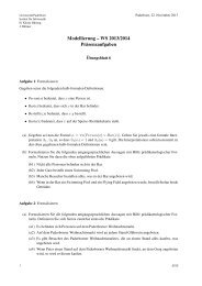
a test track in the scale <strong>of</strong> 1:2.5 such that the ideas <strong>of</strong> the<br />
project are not only tested ”on paper” but in real operation<br />
(cf. Fig. 2).<br />
Figure 2. <strong>The</strong> test track and shuttle prototype<br />
<strong>of</strong> the RailCab project<br />
<strong>The</strong> vision <strong>of</strong> the RailCab project is to provide the comfort<br />
<strong>of</strong> individual traffic concerning scheduling and ondemand<br />
availability <strong>of</strong> transportation as well as individually<br />
equipped cars on the one hand, and the cost and resource effectiveness<br />
<strong>of</strong> public transport on the other hand. <strong>The</strong> modular<br />
railway system combines sophisticated undercarriages<br />
with the advantages <strong>of</strong> new actuation techniques as employed<br />
in the Transrapid (http://www.transrapid.de/en) to
increase passenger comfort while still enabling high speed<br />
transportation and (re)using the existing railway tracks.<br />
One particular aspect is to reduce the energy consumption<br />
due to air resistance by coordinating the autonomously<br />
operating shuttles in such a way that they build convoys<br />
whenever possible. Such convoys are built on-demand and<br />
shuttles travel only a few centimeters apart from each other<br />
(up to 0.5m) such that a high reduction <strong>of</strong> energy consumption<br />
is achieved. This requires a lot <strong>of</strong> information exchange<br />
between the various machines or system components like<br />
the shuttles, registrars, dispatchers, stations, customers etc.<br />
It also means a tight integration <strong>of</strong> quasi-continuous and discrete<br />
control s<strong>of</strong>tware and the realization <strong>of</strong> complex functionality<br />
by s<strong>of</strong>tware rather than hardware, because, for example,<br />
travelling only at a few centimetres distance in a convoy<br />
requires tight coordination between the various speed<br />
control units under hard real time constraints.<br />
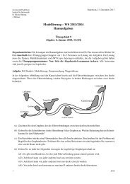
A so-called Operator-Controller-Module (OCM) as depicted<br />
in Fig. 3 (cf. [21]) describes a general architectural<br />
model <strong>of</strong> a single machine or system component and identifies<br />
its constituent parts.<br />
Figure 3. OCM architecture and its elements<br />
<strong>The</strong> OCM reflects the strict hierarchical construction <strong>of</strong><br />
a system component including the hardware components:<br />
(1) On the lowest level <strong>of</strong> the OCM, a more or less standard<br />
controller (C) implements a feedback loop based on sensor<br />
input and producing actuator control signals accordingly.<br />
This is called the motor loop. <strong>The</strong> s<strong>of</strong>tware processing is<br />
necessarily quasi-continuous, including smooth switching<br />
between possible alternative control strategies which are<br />
described by some form <strong>of</strong> differential equations or difference<br />
equations. (2) <strong>The</strong> controller is controlled by the reflective<br />
operator (RO), in which monitoring and controlling<br />
routines are executed. <strong>The</strong> reflective operator operates in<br />
a predominantly event-oriented manner and thus includes a<br />
control automaton with a number <strong>of</strong> discrete control states<br />
and transitions between them. It does not access the actuators<br />
<strong>of</strong> the system directly, but may modify the controller<br />
and initiate the switch between different control strategies.<br />
Furthermore it serves as the connecting element to the cognitive<br />
level <strong>of</strong> the OCM. (3) <strong>The</strong> topmost level <strong>of</strong> the OCM<br />
is called the cognitive operator (CO). On this level, the system<br />
can gather information concerning itself and its environment<br />
and use it for the improvement <strong>of</strong> its own behavior,<br />
i.e. possibly complex, time-consuming computations<br />
for long-range planning. This level introduces intelligent<br />
behaviour and consequently such components could also be<br />
called agents.<br />
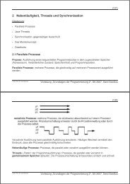
Figure 4. <strong>The</strong> OCM hierarchy <strong>of</strong> a shuttle and<br />
its connections with other shuttles<br />
<strong>The</strong> OCM hierarchy can be nested, i.e. each nesting level<br />
may include an OCM which however does not include the<br />
controller part. Controllers, which implement the continuous<br />
part <strong>of</strong> the s<strong>of</strong>tware, usually exist only on the leaf level<br />
<strong>of</strong> a nested OCM hierarchy. As an example, consider the<br />
above mentioned shuttles <strong>of</strong> the RailCab project. <strong>The</strong> architecture<br />
is defined by OCMs w.r.t. the reflective operators<br />
and the controllers as depicted in Fig. 4. A shuttle consists<br />
<strong>of</strong> components like the suspension/tilt module, the engine,<br />
or the steering module. <strong>The</strong>y will utilize the same hardware<br />
(actuators, sensors and controller) but their s<strong>of</strong>tware is defined<br />
by OCMs as is the s<strong>of</strong>tware <strong>of</strong> the shuttle.<br />
As a complete mechatronic system usually consists <strong>of</strong><br />
several concurrently running components, there exists a further<br />
possibility <strong>of</strong> communication between components besides<br />
the strict hierarchical control flow. Top-level OCMs<br />
<strong>of</strong> several nested hierarchies, which usually represent a major<br />
system component, may act as freely interacting agents.<br />
This means that agents exchange information but no cen-
tral control is defined anymore. As examples <strong>of</strong> such major<br />
system components consider the different shuttles, stations,<br />
job brokers and dispatchers <strong>of</strong> the RailCab project.<br />
Such a system as RailCab exhibits all the features <strong>of</strong> a<br />
next generation mechatronic system, namely high degree<br />
<strong>of</strong> concurrency, no central control, the necessity for selfcoordination,<br />
a possible reconfiguration <strong>of</strong> the system at<br />
runtime due to the volatility <strong>of</strong> system components, and the<br />
emergence <strong>of</strong> new system properties because <strong>of</strong> the cooperation<br />
<strong>of</strong> (intelligent) agents. It also faces challenges which<br />
have been only partly addressed appropriately by the development<br />
methods <strong>of</strong> state-<strong>of</strong>-the-art mechatronic systems<br />
like s<strong>of</strong>tware running under hard real time constraints, the<br />
integration <strong>of</strong> continuous and discrete control units and a<br />
high demand for quality as such a system is <strong>of</strong>ten used in<br />
and built for safety-critical applications.<br />
3 State <strong>of</strong> the Art<br />
Modelling & Tools. In a certain sense, modelling and<br />
even model driven development, i.e. the generation <strong>of</strong> executable<br />
code from a model, has long been existing in the<br />
mechatronic world to improve s<strong>of</strong>tware quality based on<br />
model analysis. Classical feedback controllers as sketched<br />
above, are specified by a combination <strong>of</strong> block diagrams<br />
and differential equations. Typically platform specific code<br />
is generated from such a moel specifcation.<br />
A feedback controller has to be designed in such a way<br />
that excitations and disturbances do not lead to oscillations<br />
which, in the case <strong>of</strong> a shuttle for instance might even result<br />
in a collision or derailment. If a controller holds the output<br />
on a desired value or within a given range even after an<br />
excitation or disturbance, the whole system is called stable.<br />
In some cases, it might be necessary to switch between<br />
different controllers, i.e. exchange one controller by another<br />
one. This could lead to a (discrete) jump in the output signal<br />
which again might result in unintended oscillations. To<br />
avoid those also called unstable situations, a so-called output<br />
cross fading function is defined. This function specifies<br />
the time needed to fade out the output <strong>of</strong> the controller<br />
which is to be replaced while fading in the output <strong>of</strong> the new<br />
controller.<br />
Many commercial tools support the specification <strong>of</strong> controller<br />
models by block diagrams and differential equations.<br />
In addition, they provide for simulation <strong>of</strong> the specified<br />
model, <strong>of</strong>ten in terms <strong>of</strong> viewgraphs, to support analysis <strong>of</strong><br />
the model. Numerous solutions exist to generate platform<br />
specific code, <strong>of</strong>ten for very specialized hardware. However,<br />
this code generation is usually not flexible, i.e. the<br />
particular code generator is domain or mostly even target<br />
platform specific.<br />
<strong>The</strong> de-facto standard tool, which is most widely used in<br />
measured<br />
variables<br />
processor<br />
mechanical<br />
system<br />
controlled<br />
variables<br />
sensor actuator<br />
Figure 5. <strong>The</strong> interplay between mechatronic<br />
components<br />
many industrial applications, is Matlab/Simulink which is<br />
developed and commercialized by Mathworks.<br />
However, modelling (and corresponding analysis) gets<br />
a lot more difficult when not only stand-alone controllers<br />
have to be developed but a usually complex network <strong>of</strong><br />
those systems has to be built, as exemplified by the railcab<br />
system. Here, not only a shuttle in itself contains<br />
such a complex network but also the necessary connection<br />
and communication <strong>of</strong> shuttles, stations, brokers, users etc.<br />
forms such a network. In addition, each network component<br />
is more complicated than a single controller as indicated<br />
in the OCM hierarchy by the reflective operator and cognitive<br />
operator levels respectively. In fact, components now<br />
also exhibit discrete behaviour, maintain corresponding data<br />
structures to be able to learn from history and communicate<br />
extensively with their environment based on possibly complex<br />
communication protocols and not only by (simple) sensor<br />
input.<br />
This situation made it necessary to introduce concepts<br />
for modelling discrete systems. (Static) component models<br />
and corresponding discrete behaviour have to specified.<br />
Component models are usually represented by class or<br />
component diagrams resp., where the UML 2.0 component<br />
model and especially its extension the <strong>Systems</strong> Modelling<br />
Language SysML [31] could be considered now a de-facto<br />
standard to be used for this purpose. SysML is a response<br />
to OMGs request for a proposal <strong>of</strong> a UML for systems engineering.<br />
In SysML blocks specify the fine-grained structure<br />
<strong>of</strong> a class extended by continuous communication links between<br />
ports. Continuous components are specified by parametric<br />
constraints on class attribute values expressing corresponding<br />
differential equations.<br />
Component models are also defined domain specific with<br />
AUTOSAR being one <strong>of</strong> the most prominent examples.<br />
AUTomotive Open System ARchitecture is an international<br />
project <strong>of</strong> leading car manufacturers and suppliers with the<br />
goal to develop and establish a standard architecture for<br />
electrical and electronic components in cars. It defines major<br />
architectural components and interfaces to enable the ex-
change <strong>of</strong> s<strong>of</strong>tware (and underlying hardware) easily. <strong>The</strong><br />
leading principle is ”Cooperate on standards - compete on<br />
implementation”.<br />
More advanced concepts how to build the architecture<br />
or component model <strong>of</strong> even self-managed systems are described<br />
in [26].<br />
Widely used approaches to model behaviour are Petri<br />
Nets and many kinds <strong>of</strong> finite state machines called state<br />
charts, state flow diagrams and sometimes even data flow<br />
diagrams. Except the most notable definitions <strong>of</strong> timed automata<br />
and timed Petri Nets, they usually lack in describing<br />
especially timing constraints which are needed to model and<br />
analyse time critical applications as mechatronic systems.<br />
Again many commercial tools, especially from the s<strong>of</strong>tware<br />
engineering domain like Rational Rose, support modelling<br />
the component structure and discrete behaviour.<br />
Tools from the engineering domain like Matlab and in<br />
particular its extension by Stateflow also support modelling<br />
discrete behaviour however in a very limited sense. Only<br />
support for modelling simple state charts is provided but no<br />
support for defining component structures and especially no<br />
support to define time constraints is available.<br />
<strong>The</strong> key issue is however to model discrete and continous<br />
behaviour in a uniform approach also including the<br />
modelling <strong>of</strong> the usually complex component hierarchy as<br />
exemplified by the following example taken from [13].<br />
Figure 6. A sample <strong>of</strong> a hybrid statechart<br />
In Fig. 6 the internal behavior <strong>of</strong> a Shuttle component<br />
is defined by a so-called Hybrid Realtime State Chart<br />
(HRTSC). As an example for a typical real-time requirement,<br />
a deadline interval d1 is used to describe that the state<br />
change from state noConvoy to state convoyFront has<br />
to be finished within a given interval. Similarly, deadlines<br />
are defined to constrain the time an object may remain in<br />
a certain state. Guards <strong>of</strong> transitions may contain conditions<br />
which depend on the status <strong>of</strong> a clock. When defining<br />
the constraints which express the reconfiguration <strong>of</strong> controllers,<br />
like when switching between state convoyFront<br />
and noConvoy respectively, the above mentioned fading<br />
functions have to be considered and represent lower and upper<br />
limits for those constraints. A HRTSC is an extension<br />
<strong>of</strong> a Realtime State Chart where a certain controller configuration<br />
can be assigned to a particular state. In the example<br />
two different types <strong>of</strong> speed controllers exist which are<br />
used depending on the shuttle running in convoy mode or in<br />
non convoy mode including running at the top <strong>of</strong> a convoy.<br />
<strong>The</strong> Velocity controller controls speed based on some input<br />
by a user or dispatching system and the current speed <strong>of</strong><br />
course, whereas the Distance controller has also to observe<br />
the speed <strong>of</strong> shuttles running in front <strong>of</strong> it.<br />
Code Generation. Based on such a specification, model<br />
based development ideally requires the generation <strong>of</strong> code<br />
which meets all realtime constraints as defined in the model<br />
specification. This requires the code generator to know<br />
about all platform specific constraints like speed and number<br />
<strong>of</strong> processors or available memory.<br />
Only a very few research oriented approaches exist to<br />
support a uniform modelling <strong>of</strong> the behaviour <strong>of</strong> all system<br />
components including the specification <strong>of</strong> realtime constraints<br />
and a corresponding code generation. [21, 25, 10, 2,<br />
9] present first steps to provide for support <strong>of</strong> e.g. hierarchical<br />
modelling, reconfiguration <strong>of</strong> controller configurations<br />
as well as a smooth integration with the definition <strong>of</strong> static<br />
component structures and especially the specification conformant<br />
code generation.<br />
Processes. <strong>The</strong> above description focussed on modelling<br />
the s<strong>of</strong>tware part <strong>of</strong> mechatronic systems. One <strong>of</strong> the most<br />
prominent problems in current industrial development and<br />
even research approaches is however the lack <strong>of</strong> integration<br />
between the different disciplines, namely mechanical and<br />
electrical engineering and computer science or s<strong>of</strong>tware engineering<br />
more specifically. <strong>The</strong> current situation is usually<br />
characterized as the ”throw it over the wall” approach. Usually,<br />
the mechanical engineer starts with designing the shape<br />
and mechanical parts, then the electrical engineer plans the<br />
wiring and finally the s<strong>of</strong>tware engineer has to write the<br />
code. Obviously, this approach leads to a lot <strong>of</strong> design errors<br />
and costly rework when it is finally noticed that some<br />
parts do not fit together or the simple layout <strong>of</strong> processors<br />
and memory make certain s<strong>of</strong>tware solutions impossible.<br />
Analysis & Tools. A rather large percentage <strong>of</strong> mechatronic<br />
systems are deployed in safety critical areas (e.g. the<br />
automotive or rail domain, see [29, 11, 5] for model-based<br />
developments in the automotive domain). This makes analysis<br />
<strong>of</strong> mechatronic systems (or first <strong>of</strong> all, their models)<br />
one <strong>of</strong> the main areas <strong>of</strong> work for s<strong>of</strong>tware engineers employed<br />
in the design <strong>of</strong> such systems. Since its invention<br />
in the ’80ties model checking [15] has become a standard<br />
technique for verification, in particular for hardware systems.<br />
<strong>The</strong> main advantage <strong>of</strong> model checking which makes<br />
it interesting for mechatronic systems is its (almost) full<br />
automation, providing tool support for analysis. Notwithstanding<br />
recent advances and success stories, the main challenge<br />
is still the so-called state explosion problem: model
checking techniques (most <strong>of</strong>ten) rely on a search <strong>of</strong> the<br />
whole state space, and this can grow to arbitrarily large dimensions.<br />
Thus research in the area <strong>of</strong> automatic verification<br />
today focuses on fighting the state explosion problem<br />
(for a discussion <strong>of</strong> current approaches to s<strong>of</strong>tware model<br />
checking see [18]). While in the past several standalone approaches<br />
have been developed (e.g. symbolic model checking<br />
with BDDs [16], the use <strong>of</strong> SAT solvers in bounded<br />
model checking [12], powerful reduction techniques like<br />
abstraction and partial-order reduction [3, 17, 27]), current<br />
work focuses on the tight integration <strong>of</strong> these techniques:<br />
SAT solvers are combined with decision procedures (giving<br />
so-called SMT-solvers, see e.g. [4]), model checking with<br />
specific AI search methods [19], bounded model checking<br />
is parallelised [1] or model checking combined with static<br />
analysis methods [6]. Prototype tools supporting these new<br />
developments are under development.<br />
<strong>Mechatronic</strong> systems present a further challenge for verification<br />
as they belong to the area <strong>of</strong> hybrid systems, characterised<br />
by a combination <strong>of</strong> discrete and continuous parts.<br />
<strong>The</strong> s<strong>of</strong>tware constitutes the discrete part, while the continous<br />
dynamics corresponds to the physical system with its<br />
sensors and actuators. Verification <strong>of</strong> hybrid systems today<br />
is still in its infancy. Well understood is the subclass <strong>of</strong><br />
timed systems, where the only continous part is the change<br />
<strong>of</strong> time. System models in this class are written as timed<br />
automata, and a number <strong>of</strong> tools (most prominently Uppaal<br />
[8] and Kronos [34]) support verification <strong>of</strong> timed automata<br />
with respect to reachability or even temporal logic specified<br />
properties. For hybrid systems, analysis tools supporting<br />
particular classes <strong>of</strong> continous dynamics (e.g. algebraic constraints<br />
or linear hybrid automata) are for instance HyTech<br />
[24] and CheckMate [30]. Automation can still only partially<br />
be achieved, the algorithms employed in the model<br />
checking are not guaranteed to terminate anymore. In order<br />
to make the actual system fit into the required subclass, approximations<br />
<strong>of</strong> the real system are used (with the risk <strong>of</strong><br />
loosing precision).<br />
<strong>The</strong> approach to verification taken in the RailCab project<br />
embodies a combination <strong>of</strong> a number <strong>of</strong> different techniques.<br />
<strong>The</strong> RailCab model belongs to the class <strong>of</strong> hybrid<br />
systems. <strong>The</strong> basis for the verification is the structured<br />
UML-based model <strong>of</strong> the mechatronic system, dividing it<br />
into a set <strong>of</strong> components interacting through well-specified<br />
interfaces. Verification pursues a compositional approach:<br />
instead <strong>of</strong> analysing the system as a whole (which is not<br />
in the range <strong>of</strong> automatic methods), components together<br />
with parts <strong>of</strong> the environment are verified separately. <strong>The</strong><br />
context <strong>of</strong> a component, i.e. the relevant part <strong>of</strong> the environment<br />
to be considered therein, can be determined by<br />
the specific role that the component takes on in the system.<br />
<strong>The</strong> results <strong>of</strong> these separate analysis’ can be combined<br />
into a verification result for the complete system us-<br />
ing an assume-guarantee style [23]. For the verification <strong>of</strong><br />
single components, which in particular embody controllers<br />
and thus continous parts, a combination <strong>of</strong> model checking,<br />
abstraction and testing is used. Controllers are modelled as<br />
timed automata and thus only constitute abstractions <strong>of</strong> the<br />
continuous behaviour. <strong>The</strong> correctness <strong>of</strong> this abstraction is<br />
checked by the mechanical engineers who – besides having<br />
a rich knowledge <strong>of</strong> controllers - actually carry out a lab<br />
testing <strong>of</strong> the behaviour. Verification <strong>of</strong> a single component<br />
and its context is then automatically carried out using the<br />
timed automata model checker Uppaal.<br />
<strong>The</strong>re are some important prerequisites for this type <strong>of</strong><br />
verification which we believe are fundamental for any type<br />
<strong>of</strong> analysis for mechatronic systems:<br />
• a structured component-oriented model with welldefined<br />
small interfaces between components,<br />
• a precise formal description <strong>of</strong> components (on a certain<br />
level <strong>of</strong> abstraction) and<br />
• confidence in the abstractions taken (at the best supported<br />
by another analysis technique if unfeasible for<br />
model checking).<br />
Still, this is not the end to verification. <strong>The</strong> analysis<br />
results are only transferable to the actual realisation if the<br />
assumptions made in the model (for instance on port-toport<br />
connections, communication times, etc.) are met in<br />
the physical realisation. This has to be guaranteed by on the<br />
one hand code generation and the other hand the mechanical<br />
and electronical realisation.<br />
4 Future developments and research challenges<br />
We believe that future mechatronic systems will consist<br />
<strong>of</strong> several autonomously acting agents capable <strong>of</strong> monitoring<br />
their own physical environment as well exchanging information<br />
with other agents. <strong>The</strong> presence <strong>of</strong> this additional<br />
information will give rise to completely new possibilities <strong>of</strong><br />
adaptation, which go well beyond what s<strong>of</strong>tware control in<br />
mechatronic systems is currently achieving. This trend is<br />
further supported by the emerging new techniques in network<br />
technology, e.g. wireless adhoc networks. Constructing<br />
the s<strong>of</strong>tware <strong>of</strong> such advanced systems requires a number<br />
<strong>of</strong> significant changes <strong>of</strong> current s<strong>of</strong>tware engineering<br />
techniques. In particular, the following issues have to be<br />
addressed to build the next generation systems properly.<br />
• Current s<strong>of</strong>tware design processes are tailored towards<br />
a particular domain rather than spanning over all involved<br />
domains. So-called concurrent engineering is<br />
rather a goal than reality in practice.
• Modelling formalisms allow for a description <strong>of</strong> static<br />
systems but not for their volatility. Model transformations<br />
are ment for transforming models towards a<br />
particular use on a platform but not for describing the<br />
change that a model (viz. the modelled system) itself<br />
may undergo during its lifetime.<br />
• Analysis techniques mainly rely on the knowledge<br />
about a global state space and cannot cope with properties<br />
only emerging due to the volatility <strong>of</strong> systems.<br />
• Secure exchange <strong>of</strong> information is usually based on<br />
a central unit keeping public keys <strong>of</strong> participants and<br />
cannot manage decentralised highly distributed systems<br />
<strong>of</strong> agents dynamically buiding as well as resolving<br />
clusters. Communication in future mechatronic<br />
systems will however cross the borders <strong>of</strong> one agent<br />
and thus has to be secured.<br />
While the latter is clearly a task for cryptography and<br />
network technology all <strong>of</strong> the former ones are challenges for<br />
s<strong>of</strong>tware engineering, sometimes necessarily in cooperation<br />
with the other disciplines.<br />
Processes. <strong>The</strong> existing ”throw it over the wall” approach<br />
as the basis <strong>of</strong> a development process is <strong>of</strong> course a result<br />
<strong>of</strong> traditional development where the mechanical part <strong>of</strong> a<br />
system used to be the most complex and difficult one. Psychological<br />
barriers in the heads <strong>of</strong> developers, who do not<br />
want to loose the overall control, are one <strong>of</strong> the main reasons<br />
for the current situation but not the only one. Technically,<br />
a different and somewhat overlapping terminology<br />
is being used which <strong>of</strong>ten hampers common understanding.<br />
As an example just take the word version which in s<strong>of</strong>tware<br />
engineering usually addresses the change <strong>of</strong> a piece <strong>of</strong> s<strong>of</strong>tware<br />
over time. In mechanical engineering, version is a new<br />
product which has come out <strong>of</strong> a complex design and development<br />
process like the new version <strong>of</strong> a car. Consequently,<br />
related terms like variant and configuration are also used in<br />
slightly different meanings. Deeper technical issues than<br />
just harmonizing terminology represent further challenges.<br />
In engineering, so-called product data management systems<br />
(PDM) are the central repository to store and control the intermediate<br />
results <strong>of</strong> a development process whereas s<strong>of</strong>tware<br />
version and configuration management (SCM) systems<br />
are used in the s<strong>of</strong>tware area. <strong>The</strong> PDM systems are<br />
usually initially filled by a CAD system and thus their contents<br />
is based on the definition <strong>of</strong> the constituent parts <strong>of</strong> a<br />
(new) product. If at all, s<strong>of</strong>tware is attached to these product<br />
parts. PDM systems, despite <strong>of</strong>fering some support for<br />
SCM, do not support the kind <strong>of</strong> cooperative work, frequent<br />
updates, automatic messaging, baselining etc. which SCM<br />
systems <strong>of</strong>fer. On the other hand, SCM systems do not <strong>of</strong>fer<br />
any PDM type <strong>of</strong> support, i.e. the storage <strong>of</strong> geometric<br />
shapes, the detailed product hierarchy etc. In fact, an integration<br />
<strong>of</strong> these very different lines <strong>of</strong> development for<br />
central repositories is one <strong>of</strong> the main short term goals to<br />
achieve to support true concurrent engineering.<br />
Modelling. <strong>The</strong> foremost goal <strong>of</strong> modelling must be the<br />
uniform specification <strong>of</strong> the discrete and continous parts <strong>of</strong><br />
an advanced mechatronic system across all disciplines. This<br />
includes the usually deeply nested component hierarchy, the<br />
communication structure and behaviour <strong>of</strong> components as<br />
well as the corresponding behavioural specifications.<br />
As those networks <strong>of</strong> nested components become very<br />
complex, such a uniform language must be defined in such<br />
a way that all possible syntactic checks to avoid errors must<br />
be exploited. This requires the definition <strong>of</strong> a precise static<br />
semantics (or context sensitive syntax) <strong>of</strong> the language. As<br />
much as possible, the grammar (or metamodel) <strong>of</strong> such a<br />
language must define precisely e.g. a type system <strong>of</strong> mechatronic<br />
components, a refinement notion or the conformance<br />
<strong>of</strong> required and <strong>of</strong>fered component functionality. A type<br />
system, for example, defines the permitted connections <strong>of</strong><br />
component ports whereas a refinement notion enables to<br />
check syntactically (at least to some extent) whether a component<br />
is correctly substitutable by a set <strong>of</strong> other components<br />
on the next lower hierarchy level. Of course, such<br />
a definition <strong>of</strong> refinement may not be too restrictive as to<br />
make it very complicated and cumbersome to model real<br />
world systems.<br />
As the component definition must include hardware and<br />
s<strong>of</strong>tware components, the modelling language becomes domain<br />
specific at least to a certain extent. Properties <strong>of</strong> sensors<br />
and actuators, their interfaces to s<strong>of</strong>tware control (in<br />
fact to the reflective operator), or possibly even restrictions<br />
on wiring or geometric shapes might have some influence<br />
on the way how the control s<strong>of</strong>tware is being built. This<br />
concerns, in particular, timing aspects which must be specified<br />
in the model as well, to be able to analyse the system<br />
model appropriately and to fully automatically generate<br />
code from the model specification. As a consequence<br />
a general UML-like language for all sorts <strong>of</strong> mechatronic<br />
systems in various domains such as e.g. transportation, production,<br />
or telecommunication might not exist but rather, if<br />
at all, a lot <strong>of</strong> domain specific adaptions and extensions <strong>of</strong> a<br />
possibly very general core language.<br />
Finally, the definition <strong>of</strong> a precise (dynamic) semantics<br />
<strong>of</strong> such a language represents another major challenge. <strong>The</strong><br />
current approach which is to attach code pieces to particular<br />
model elements like e.g. states or transitions in a state<br />
chart or Petri Net, when it comes down to the detailed definition<br />
<strong>of</strong> fine-grained activities or functions, is not appropriate<br />
and makes further model analysis almost impossible.<br />
Consequently, also the definition <strong>of</strong> such fine-grained activities<br />
must be definable on a more abstract level than code.
<strong>The</strong> trend towards adaptibility and self-organisation, indicated<br />
by the Cognitive Operator level in the OCM hierarchy<br />
requires further sophisticated concepts as part <strong>of</strong> a<br />
modelling language (a discussion <strong>of</strong> some <strong>of</strong> these issues<br />
can also be found in [20], in particular concerning models<br />
at runtime supporting adaptability). A model must include<br />
the precise definition <strong>of</strong> learning and improvement which<br />
basically corresponds to some kind <strong>of</strong> rule-based system expressing<br />
the permitted changes <strong>of</strong> component structure and<br />
behaviour. However, it is important to specify precisely the<br />
limits <strong>of</strong> such changes, because those changes will happen<br />
during the operation <strong>of</strong> the system and consequently should<br />
be safe. In a little more detail, one could imagine the CO developing<br />
a new plan and corresponding behaviour for a particular<br />
system component. <strong>The</strong> change initiated by the CO<br />
on the RO might require also a reconfiguration <strong>of</strong> the underlying<br />
controller structure and this might violate particular<br />
timing constraints which have been specified before. <strong>The</strong>n<br />
the change must be rejected and maybe modified by the CO.<br />
Checking those constraints vs. a proposal for change made<br />
by the CO is a very important part <strong>of</strong> keeping the system<br />
safe during runtime.<br />
As a very first step in this direction, the following example<br />
taken from the RailCab project illustrates this idea.<br />
<strong>The</strong> realtime state chart <strong>of</strong> Fig. 6 represents a (small) part<br />
<strong>of</strong> the behavioural specification <strong>of</strong> a shuttle component. A<br />
change <strong>of</strong> this behaviour could be formally and graphically<br />
expressed by a graph transformation rule.<br />
Such a rule could specify the necessary change <strong>of</strong> the automaton<br />
<strong>of</strong> Fig. 6, when the planning component <strong>of</strong> a shuttle,<br />
namely the CO, identifies a possible improvement <strong>of</strong> the<br />
shuttle behaviour which should be introduced during operation<br />
<strong>of</strong> the system. Such an improvement could be based,<br />
for example, on detecting that the protocol defined by the<br />
automaton in Fig. 6 yields a lot <strong>of</strong> network traffic, i.e. each<br />
shuttle in a convoy has to communicate with his two neighbours<br />
and, in addition, with the convoy leader (not specified<br />
in the example here). An improvement to cut down on network<br />
traffic could be to identify not only a convoy leader<br />
and the neighbours as the contact points for all other shuttles<br />
but a single reference contact point in a convoy, which<br />
takes care <strong>of</strong> all other necessary communication with the<br />
other reference contact points in the convoy. This requires<br />
the extension <strong>of</strong> the shuttle behaviour definition by a further<br />
state (called convoyMiddle here) and the corresponding<br />
state transitions. (Of course the corresponding protocol<br />
definitions have to be extended as well. As a sketch <strong>of</strong><br />
an idea, the formal definition <strong>of</strong> such a change defined by<br />
a graph transformation rule and the result <strong>of</strong> applying this<br />
rule to the state chart defining the shuttle behaviour, is given<br />
in Fig. 7.<br />
In general, such changes could include quite complex<br />
operations not only on an automaton (or Petrinet) or the like<br />
:convoyFront<br />
shuttlesInConvoy≥ 20<br />
:noConvoy :convoyRear<br />
:convoyFront :noConvoy :convoyRear<br />
Synchronization<br />
convoyFront<br />
d1<br />
isConvoyOK<br />
/ convoyOK<br />
breakConvoy /<br />
d1<br />
noConvoy<br />
<br />
when(convoyUseful)<br />
/ buildConvoy<br />
d1<br />
breakConvoy /<br />
breakConvoy<br />
<br />
H<br />
:convoyMiddle<br />
<br />
isConvoyOk<br />
/ noConvoy<br />
d1<br />
d1<br />
convoyRear<br />
when(convoyNotUseful)<br />
/ doBreakConvoy<br />
d1<br />
default<br />
d1<br />
wait<br />
[15 ≤ t0]<br />
{t0}<br />
when(!lastShuttle) when(lastShuttle)<br />
convoyMiddle<br />
Figure 7. A graph transformation rule (top)<br />
and its effect on the state chart (bottom)<br />
but also on the corresponding component structure. Component<br />
structure changes might be e.g. the creation or deletion<br />
<strong>of</strong> a port or connection or a change in the hierarchy.<br />
<strong>The</strong> advantage <strong>of</strong> using graph transformation rules is<br />
tw<strong>of</strong>old. <strong>The</strong>y are a suitable visual formalism to express<br />
changes <strong>of</strong> graph-like structures which are the basis <strong>of</strong> all<br />
visual specification formalisms. In addition, they have a<br />
well-defined formal underpinning which enables to define<br />
a formal and precise semantic definition <strong>of</strong> rule-based systems<br />
given by graph transformations.<br />
Code generation. Target platform specific code generators<br />
do not provide for enough flexibility to adjust code<br />
generation to <strong>of</strong>ten restricted but changing available hardware<br />
resources and requirements. If the code generator or<br />
rather its underlying algorithm knew about the changing<br />
constraints and the change in the model, it could generate<br />
optimized code based on currently available resources and<br />
currently needed pieces <strong>of</strong> the control s<strong>of</strong>tware. This especially<br />
concerns the generation <strong>of</strong> code which considers<br />
all realtime constraints specified in the model. <strong>The</strong> optimized<br />
code could replace the currently existing code, if the<br />
generator has been verified (see below). This would however<br />
require that a code generator is flexible enough to be<br />
adjusted to and to even influence the underlying platform.<br />
In principle, this is possible by using Field Programmable
Gate Arrays which allow for a flexible configuration <strong>of</strong> the<br />
hardware resources, i.e. available processors and memory.<br />
Analysis. From the point <strong>of</strong> view <strong>of</strong> analysis, or more<br />
specifically model checking, advanced mechatronic systems<br />
are mainly characterised by the fact that their state<br />
space is - due to the continuous parts - even larger than that<br />
<strong>of</strong> ordinary s<strong>of</strong>tware systems (<strong>of</strong>ten already too large for<br />
model checking) and sometimes also infinite. This makes<br />
verification which could achieve a formal pro<strong>of</strong> <strong>of</strong> correct<br />
functioning hard. On the other hand, their deployment in<br />
safety critical areas imposes the highest degree <strong>of</strong> reliability<br />
on mechatronic systems. This makes testing alone which<br />
remains feasible for these systems unsuitable (besides being<br />
time and cost intensive). As a consequence a third way in<br />
between has to be found which incorporates a number <strong>of</strong><br />
known analysis techniques, develops new ones and combines<br />
them all into a reliable yet practicable method. We<br />
discuss this along the lines <strong>of</strong> present and future mechatronic<br />
systems.<br />
<strong>The</strong> integration <strong>of</strong> mechanical, electronical and s<strong>of</strong>tware<br />
parts poses challenges which so far have only partly been<br />
addressed. For the analysis <strong>of</strong> today’s mechatronic systems<br />
we can identify the following shortcomings:<br />
Precise hybrid modelling No hybrid modelling techniques<br />
exist today which are able to describe the diverse<br />
parts <strong>of</strong> a mechatronic system in a uniform and -<br />
what is indispensable for analysis - precise way. Current<br />
formalisms try to simply combine some <strong>of</strong> the<br />
existing modelling language from the three areas but<br />
most <strong>of</strong>ten without giving a meaning to this mixed use<br />
<strong>of</strong> diagrams.<br />
Integrated hybrid analysis <strong>The</strong> three disciplines involved<br />
in the construction <strong>of</strong> mechatronic systems all have<br />
analysis techniques on their own. Instead <strong>of</strong> applying<br />
these in isolation, an integrated analysis framework is<br />
needed in which a particular type <strong>of</strong> analysis in one<br />
area supports/relies on/triggers an analysis in another<br />
area.<br />
Verification <strong>Systems</strong> with discrete and continuous parts<br />
are intrinsically difficult to verify. Model checking <strong>of</strong><br />
hybrid systems and the transfer <strong>of</strong> known verification<br />
techniques to the domain <strong>of</strong> hybrid systems remains a<br />
challenge.<br />
A possible line <strong>of</strong> approaching these challenges might lie<br />
in exploiting knowledge about the specific domain. <strong>Mechatronic</strong><br />
systems have particular characteristics (e.g. with respect<br />
to their structuring, the involved controllers) which<br />
might be utilized in the analysis. <strong>The</strong> structure, viz. specific<br />
combinations <strong>of</strong> discrete and continous parts, might form<br />
the basis <strong>of</strong> compositional analysis techniques for mechatronic<br />
systems. Thus, a compositional approach could integrate<br />
analysis result achieved by different techniques, in<br />
particular could combine results obtained by mechanical<br />
and electrical engineers with those <strong>of</strong> s<strong>of</strong>tware engineering.<br />
<strong>The</strong> engineer’s longstanding experience in constructing<br />
reliable systems and their specific knowledge about controllers<br />
furthermore makes it worthwhile to pursue approximation<br />
techniques that completely abstract from the continous<br />
parts. Finally, current research developments for verification<br />
tightly coupling different techniques will broaden<br />
the class <strong>of</strong> hybrid systems manageable by automatic model<br />
checking.<br />
Next generations mechatronic system will however come<br />
with new characteristics which make analysis even harder.<br />
In the future, mechatronic systems will consists <strong>of</strong> several<br />
”small” autonomous mechatronic agents, interacting with<br />
each other and adapting to changes in their environment.<br />
Adaptation according to measurements by an agent’s own<br />
sensors will be completemented by adaptations due to information<br />
obtained from other agents. <strong>The</strong> RailCab project<br />
already shows this new level <strong>of</strong> interaction: when driving in<br />
a convoy the shuttles exchange information about their positions<br />
and speed as to optimise the distance between them<br />
and thus power consumption. For analysis, this opens yet<br />
another dimension <strong>of</strong> complexity.<br />
Volatility Evolution according to new data from the environment<br />
will be one main characteristic <strong>of</strong> future advanced<br />
mechatronic systems. <strong>The</strong> behaviour <strong>of</strong> such<br />
systems will thus not be completely fixed during design,<br />
but is allowed to adapt to environmental changes.<br />
<strong>The</strong> permitted degree <strong>of</strong> change might partially be<br />
laid down by model transformations being part <strong>of</strong> the<br />
model itself. Verification thus has to show that the system<br />
remains safe under all possible influences from the<br />
environment.<br />
A possible way <strong>of</strong> tackling volatility in the analysis are<br />
methods reasoning on the changes themselves. Currently,<br />
such techniques take the following approach: correctness<br />
properties are proven for the initial states (<strong>of</strong> the system)<br />
and in addition shown to be preserved under transitions <strong>of</strong><br />
the state. Examples <strong>of</strong> this are inductive verification techniques<br />
like [14, 28, 7] or methods for change analysis and<br />
property preservation for inheritance [32, 33]. For volatile<br />
mechatronic systems, such methods need to be lifted to<br />
transformations <strong>of</strong> the model itself. A prerequisite – like<br />
for all analysis techniques – is again a precise description<br />
<strong>of</strong> model transformations. Safety properties then have to be<br />
shown to be preserved under all possible transformations.<br />
An example illustrating this idea is again taken from the<br />
RailCab project. Consider the definition <strong>of</strong> model changes
defined by a system <strong>of</strong> graph transformation rules. Such<br />
a system <strong>of</strong> course might define an infinite state space <strong>of</strong><br />
possible changes to a given model. <strong>The</strong> problem is now<br />
to check whether none <strong>of</strong> these changes produces a model<br />
which violates certain constraints. Standard techniques<br />
which are based on exploring all reachable states obviously<br />
must fail. Here the approach is to define upfront which<br />
models or rather small cutouts <strong>of</strong> models expressed by a<br />
graph-like description represent violations <strong>of</strong> constraints.<br />
<strong>The</strong>n an inductive check takes a backward approach and<br />
tries to verify whether a backward application <strong>of</strong> a rule produces<br />
a correct model from an incorrect one, i.e. one which<br />
violates certain constraints. If this is the case, one can deduce<br />
that the rule could produce an incorrect model if applied<br />
in forward mode. This strategy might lead to detecting<br />
false positives, i.e. rules which actually do not produce incorrect<br />
models but it can still be used as an indication to the<br />
modeller or warning to an engineer that something might go<br />
wrong.<br />
As an example, take the change sketched above which<br />
introduces the role <strong>of</strong> a convoyLeader and thereby changes<br />
the behavioural definition <strong>of</strong> a shuttle component. A constraint<br />
to be checked could be that the extension to the specification,<br />
namely the introduction <strong>of</strong> the new state and its<br />
corresponding transitions, does not violate existing timing<br />
constraints <strong>of</strong> the transitions <strong>of</strong> the existing model.<br />
Finally, in the future this trend will brings us to selforganising<br />
mechatronic systems. <strong>The</strong>se will partially be inspired<br />
by biological systems, where agents have the ability<br />
to reflect upon their own behaviour and to learn from others.<br />
Agents will act on their own behalf, trying to optimise their<br />
own benefits. This objective <strong>of</strong> local optimisation might necessitate<br />
forming coalitions with as well as competing for<br />
limited resources against other agents. In such a scenario,<br />
analysis has to cope with yet another phenomenon.<br />
Emergence In self-organising systems new, unforeseen<br />
properties can emerge. For the analysis this means that<br />
the state space, which normally is the basis for verification,<br />
is unknown or not available for inspection.<br />
Analysis can only rely on incomplete, most likely local,<br />
knowledge about the system. <strong>The</strong> influence from<br />
the environment <strong>of</strong> an agent is unpredictable.<br />
It is unclear today how an analysis framework for such advanced<br />
systems might look like. Most likely, it comprises<br />
all the before mentioned techniques which are combined<br />
in an integrated framework. Furthermore, as the aspect<br />
<strong>of</strong> self-organisation particularly introduces interaction with<br />
initially unknown components, the use <strong>of</strong> games in verification<br />
could be a promising approach.<br />
As the analysis only takes place on the level <strong>of</strong> the model,<br />
safety <strong>of</strong> the realisation can moreover only be guaranteed<br />
when additional constraints are satisfied:<br />
• Code generation has to be provably correct. Here, recent<br />
progress in research on verified compilers might<br />
prove useful, as well as current work on certified code<br />
generations [22].<br />
• Assumptions on the physical systems made in the<br />
model have to be guaranteed in the realisation. This<br />
does for instance concern communication times for<br />
network connections or worst case execution times <strong>of</strong><br />
operations. In self-organising systems with a large<br />
amount <strong>of</strong> data exchanges between components, security<br />
might furthermore become an issue.<br />
It is in particular the latter point where an involvement <strong>of</strong><br />
computer science disciplines other than s<strong>of</strong>tware engineering<br />
is needed.<br />
5 Conclusion<br />
In this article, we have sketched current and future trends<br />
in the development <strong>of</strong> mechatronic systems. In particular,<br />
we have discussed the challenges involved in the construction<br />
<strong>of</strong> future advanced systems. Summarising, these can<br />
be roughly divided into two categories: the challenges arising<br />
from the collaboration <strong>of</strong> several different discplines<br />
(which is already an issue today), and those due to the aspect<br />
<strong>of</strong> self-coordination which seems to be a main characteristic<br />
distinguishing current from future mechatronic systems.<br />
<strong>The</strong>se are challenges to all involved disciplines, but<br />
in particular to s<strong>of</strong>tware engineering. Key to a success in<br />
mastering them is the joint effort and collaboration <strong>of</strong> disciplines,<br />
within computer science as well as between computer<br />
science and engineering.<br />
References<br />
[1] E. Ábrahám, T. Schubert, B. Becker, M. Fränzle, and<br />
C. Herde. Parallel SAT solving in bounded model checking.<br />
In Proc. <strong>of</strong> PDMC’06, Lecture Notes in Computer Science.<br />
Springer Verlag, 2006.<br />
[2] R. Alur, F. Ivancic, J. Kim, I. Lee, and O. Sokolsky. Generating<br />
embedded s<strong>of</strong>tware from hierarchical hybrid models.<br />
In Proceedings <strong>of</strong> the 2003 ACM SIGPLAN conference on<br />
Language, compiler, and tool for embedded systems, pages<br />
171–182. ACM Press, 2003.<br />
[3] T. Ball, A. Podelski, and S. K. Rajamani. Boolean and<br />
Cartesian Abstraction for Model Checking C Programs. In<br />
T. Margaria and W. Yi, editors, TACAS, volume 2031 <strong>of</strong> Lecture<br />
Notes in Computer Science, pages 268–283. Springer,<br />
2001.<br />
[4] C. Barrett, L. de Moura, and A. Stump. SMT-COMP: Satisfiability<br />
Modulo <strong>The</strong>ories Competition. In K. Etessami<br />
and S. Rajamani, editors, 17th International Conference on<br />
Computer Aided Verification, pages 20–23. Springer, 2005.
[5] A. Bauer, M. Broy, J. Romberg, B. Schätz, P. Braun, U. Freund,<br />
N. Mata, R. Sandner, and D. Ziegenbein. AutoMoDe<br />
— Notations, Methods, and Tools for Model-Based Development<br />
<strong>of</strong> Automotive S<strong>of</strong>tware. In Proceedings <strong>of</strong> the SAE<br />
2005 World Congress. Society <strong>of</strong> Automotive Engineers,<br />
2005.<br />
[6] J. Bauer, I. Schaefer, T. Toben, and B. Westphal. Specification<br />
and Verification <strong>of</strong> Dynamic Communication <strong>Systems</strong>.<br />
In K. Goossens and L. Petrucci, editors, Proceedings <strong>of</strong> the<br />
6th International Conference on Application <strong>of</strong> Concurrency<br />
to System Design (ACSD 2006), Turku, Finland, June 2006.<br />
IEEE.<br />
[7] B. Becker, D. Beyer, H. Giese, F. Klein, and D. Schilling.<br />
Symbolic Invariant Verification for <strong>Systems</strong> with Dynamic<br />
Structural Adaptation. In Proc. <strong>of</strong> the 28 th International<br />
Conference on S<strong>of</strong>tware Engineering (ICSE), Shanghai,<br />
China. ACM Press, 2006.<br />
[8] G. Behrmann, A. David, K. G. Larsen, O. Möller, P. Pettersson,<br />
and W. Yi. Uppaal - Present and Future. In 40th<br />
IEEE Conference on Decision and Control. IEEE Computer<br />
Society Press, 2001.<br />
[9] K. Bender, M. Broy, I. Peter, A. Pretschner, and T. Stauner.<br />
Model based development <strong>of</strong> hybrid systems. In Modelling,<br />
Analysis, and Design <strong>of</strong> Hybrid <strong>Systems</strong>, volume 279 <strong>of</strong> Lecture<br />
Notes on Control and Information Sciences, pages 37–<br />
52. Springer Verlag, July 2002.<br />
[10] K. Berkenkötter, S. Bisanz, U. Hannemann, and J. Peleska.<br />
Executable HybridUML and its Application to Train Control<br />
<strong>Systems</strong>. In H. Ehrig, W. Damm, J. Desel, M. Große-Rhode,<br />
W. Reif, E. Schnieder, and E. Westkämper, editors, Integration<br />
<strong>of</strong> S<strong>of</strong>tware Specification Techniques for Applications<br />
in Engineering, volume 3147 <strong>of</strong> Lecture Notes in Computer<br />
Science, pages 145–173. Springer Verlag, 2004.<br />
[11] E. Böde, W. Damm, J. Høyem, B. Josko, J. Niehaus, and<br />
M. Segelken. Adding value to automotive models. In<br />
M. Broy, I. H. Krüger, and M. Meisinger, editors, ASWSD,<br />
volume 4147 <strong>of</strong> Lecture Notes in Computer Science, pages<br />
86–102. Springer, 2004.<br />
[12] J. Burch, E. M. Clarke, K. L. McMillan, D. Dill, and<br />
J. Hwang. Symbolic Model Checking: 10 2 0 States and Beyond.<br />
Information and Computation, 98(2):142–170, 1992.<br />
[13] S. Burmester, M. Tichy, and H. Giese. Modeling Reconfigurable<br />
<strong>Mechatronic</strong> <strong>Systems</strong> with <strong>Mechatronic</strong> UML. In<br />
Proc. <strong>of</strong> Model Driven Architecture: Foundations and Applications<br />
(MDAFA 2004), Linköping, Sweden (U. A¨smann,<br />
ed.), pages 155–169, June 2004.<br />
[14] E. Clarke, A. Biere, A. Cimatti, and Y. Zhu. Symbolic<br />
Model Checking Without BDDs. In TACAS 99, number<br />
1579 in Lecture Notes in Computer Science, pages 193–207,<br />
1999.<br />
[15] E. Clarke, O. Grumberg, and D. Peled. Model checking.<br />
MIT Press, 1999.<br />
[16] E. M. Clarke, A. Biere, R. Raimi, and Y. Zhu. Bounded<br />
Model Checking Using Satisfiability Solving. Formal Methods<br />
in System Design, 19(1):7–34, 2001.<br />
[17] E. M. Clarke, O. Grumberg, S. Jha, Y. Lu, and H. Veith.<br />
Counterexample-guided abstraction refinement for symbolic<br />
model checking. JACM, 50(5):752–794, 2003.<br />
[18] M. Dwyer, J. Hatcliff, Robby, C. Pasareanu, and W. Visser.<br />
Formal S<strong>of</strong>tware Analysis - Emerging Trends in S<strong>of</strong>tware<br />
Model Checking. In L. Briand and A. Wolf, editors, ICSE:<br />
Future <strong>of</strong> S<strong>of</strong>tware Engineering Track, 2007.<br />
[19] S. Edelkamp, S. Leue, and A. Lluch-Lafuente. Directed<br />
Explicit-State Model Checking in the Validation <strong>of</strong> Communication<br />
Protocols. International Journal on S<strong>of</strong>tware Tools<br />
for Technology Transfer, 5(2-3):247–267, 2004.<br />
[20] R. France and B. Rumpe. Model-driven Development <strong>of</strong><br />
Complex S<strong>of</strong>tware: A Research Roadmap. In L. Briand<br />
and A. Wolf, editors, ICSE: Future <strong>of</strong> S<strong>of</strong>tware Engineering<br />
Track, 2007.<br />
[21] H. Giese, S. Burmester, W. Schäfer, and O. Oberschelp.<br />
Modular Design and Verification <strong>of</strong> Component-Based<br />
<strong>Mechatronic</strong> <strong>Systems</strong> with Online-Reconfiguration. In Proc.<br />
<strong>of</strong> 12th ACM SIGSOFT Foundations <strong>of</strong> S<strong>of</strong>tware Engineering<br />
2004 (FSE 2004), Newport Beach, USA, pages 179–188.<br />
ACM Press, November 2004.<br />
[22] H. Giese, S. Glesner, J. Leitner, W. Schäfer, and R. Wagner.<br />
Towards Verified Model Transformations. In Proc. <strong>of</strong> the<br />
3 rd Workshop on Model design and Validation (MoDeV 2 a),<br />
October 2006.<br />
[23] H. Giese, M. Tichy, S. Burmester, W. Schäfer, and S. Flake.<br />
Towards the Compositional Verification <strong>of</strong> Real-Time UML<br />
Designs. In Proc. <strong>of</strong> the European S<strong>of</strong>tware Engineering<br />
Conference (ESEC), Helsinki, Finland, pages 38–47. ACM<br />
Press, September 2003.<br />
[24] T. Henzinger, P.-H. Ho, and H. Wong-Toi. HyTech: A Model<br />
Checker for Hybrid <strong>Systems</strong>. S<strong>of</strong>tware Tools for Technology<br />
Transfer, (1):110–122, 1997.<br />
[25] T. A. Henzinger, C. M. Kirsch, M. A. Sanvido, and W. Pree.<br />
From Control Models to Real-Time Code Using Giotto.<br />
In IEEE Control <strong>Systems</strong> Magazine 23(1):50-64, 2003. A<br />
preliminary report on this work appeared in C.M. Kirsch,<br />
M.A.A. Sanvido, T.A. Henzinger, and W. Pree, A Giottobased<br />
helicopter control system, Proceedings <strong>of</strong> the Second<br />
International Workshop on Embedded S<strong>of</strong>tware (EMSOFT),<br />
Lecture Notes in Computer Science 2491, Springer-Verlag,<br />
2002, pp. 46-60., 2002.<br />
[26] J. Kramer and J. Magee. Self-Managed <strong>Systems</strong>: an Architectural<br />
Challenge. In L. Briand and A. Wolf, editors, ICSE:<br />
Future <strong>of</strong> S<strong>of</strong>tware Engineering Track, 2007.<br />
[27] C. Loiseaux, S. Graf, J. Sifakis, A. Bouajjani, and S. Bensalem.<br />
Property preserving abstractions for the verification<br />
<strong>of</strong> concurrent systems. Formal methods in system design,<br />
6:1–35, 1995.<br />
[28] Z. Manna and A. Pnueli. <strong>The</strong> Temporal Verification <strong>of</strong> Reactive<br />
and Concurrent <strong>Systems</strong> - Safety Properties. Springer,<br />
1995.<br />
[29] M. Mutz, M. Huhn, U. Goltz, and C. Krömke. Model Based<br />
System Development in Automotive. In Proceedings SAE<br />
World Congress. Society <strong>of</strong> Automotive Engineers, 2003.<br />
[30] B. I. Silva and B. H. Krogh. Formal Verification <strong>of</strong> Hybrid<br />
System Using CheckMate: A Case Study. In American Control<br />
Conference, 2000.<br />
[31] S. M. L. S. S. SysML Partner, November 2005. version 1.0<br />
alpha, document ad/05-11-14.<br />
[32] H. Wehrheim. Inheritance <strong>of</strong> Temporal Logic Properties. In<br />
FMOODS 2003: Formal Methods for Open Object-based
Distributed <strong>Systems</strong>, number 2884 in LNCS, pages 79–93.<br />
Springer, 2003.<br />
[33] H. Wehrheim. Preserving Properties under Change. In<br />
F. de Boer, M. Bonsague, and W. de Roever, editors, Formal<br />
Methods for Components and Objects, volume 3188 <strong>of</strong><br />
LNCS. Springer, 2004.<br />
[34] S. Yovine. Kronos: A verification tool for real-time systems.<br />
S<strong>of</strong>tware Tools for Technology Transfer, 1(1/2), 1997.