Communicator Protocol Appendix Modbus
Communicator Protocol Appendix Modbus
Communicator Protocol Appendix Modbus

You also want an ePaper? Increase the reach of your titles
YUMPU automatically turns print PDFs into web optimized ePapers that Google loves.
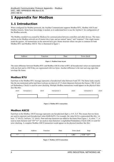
AnyBus® <strong>Communicator</strong> <strong>Protocol</strong> <strong>Appendix</strong> - <strong>Modbus</strong>DOC. ABC-APPENDIX-MB Rev.0.912001-08-011 <strong>Appendix</strong> for <strong>Modbus</strong>1.1 IntroductionWhen configured for <strong>Modbus</strong> protocols, the AnyBus <strong>Communicator</strong> supports <strong>Modbus</strong> RTU, <strong>Modbus</strong> ASCII and<strong>Modbus</strong> Generic. Some basic knowledge is needed, as to understand how to use the Anybus-C for configuration ofthe <strong>Modbus</strong> network.The <strong>Modbus</strong> standard was created by Modicon for communication between controllers and other devices. The transactionson the <strong>Modbus</strong> network are of master/slave type, and are named “query” and “response”. One single mastersends the queries. All transactions on the network have got a frame structure where one part is common for both<strong>Modbus</strong> RTU and <strong>Modbus</strong> ASCII. This is illustrated in figure 1.Address Function Data Error checkFigure 1: <strong>Modbus</strong> frame layoutThe main difference between <strong>Modbus</strong> RTU and <strong>Modbus</strong> ASCII is that in RTU all hexadecimal values are representedwith one byte and in ASCII they are represented with two bytes. Another difference is the start and stop signs thatenvelope the frame.<strong>Modbus</strong> RTUEach byte in the <strong>Modbus</strong> RTU message represents a hexadecimal value between 0 and 255. The frame looks exactlylike the one mentioned earlier and there is always an interval of 3.5 silent characters between the frames. CRC (CyclicalRedundancy Check) is used for error checking. Multiple <strong>Modbus</strong> transactions would appear on the physical interfacelike this:silent transaction 1 silent transaction 2 silent transaction 3 silentFigure 2: <strong>Modbus</strong> RTU transactions<strong>Modbus</strong> ASCIIEach byte in the <strong>Modbus</strong> ASCII message represents one hexadecimal digit i.e. 0-9, A-F. This means that two bytesare used to represent each hexadecimal value (0x00-0xFF). For example, the value 0x2A is represented like this: 1stbyte: "2" (0x32), 2nd byte: "A" (0x41). Start and stop characters are added to the frame from Figure 1. A colon, ":", isused as start character and "CR""LF" are used as stop characters. Longitudinal Redundancy Check (LRC) is used forerror checking. A complete <strong>Modbus</strong> ASCII transaction would appear on the physical interface like this:Start Address Function Data Error check Stop“:” LRC “CR” “LF”Figure 3: <strong>Modbus</strong> ASCII transactions4 HMS INDUSTRIAL NETWORKS AB