JTAGulator: Assisted discovery of on-chip ... - Grand Idea Studio
JTAGulator: Assisted discovery of on-chip ... - Grand Idea Studio
JTAGulator: Assisted discovery of on-chip ... - Grand Idea Studio
- No tags were found...

Create successful ePaper yourself
Turn your PDF publications into a flip-book with our unique Google optimized e-Paper software.
<str<strong>on</strong>g>Assisted</str<strong>on</strong>g> Discovery <str<strong>on</strong>g>of</str<strong>on</strong>g> On-Chip Debug InterfacesJoe <strong>Grand</strong> (@joegrand)
Agenda• Introducti<strong>on</strong>• Inspirati<strong>on</strong> / Other Art• Traditi<strong>on</strong>al HW RE Techniques• On-Chip Debug Interfaces• Design Requirements• Hardware• Firmware• Examples / Dem<strong>on</strong>strati<strong>on</strong>• Limitati<strong>on</strong>s• Future Work
Introducti<strong>on</strong>• On-<strong>chip</strong> debug interfaces are a well-knownattack vector- Can provide <strong>chip</strong>-level c<strong>on</strong>trol <str<strong>on</strong>g>of</str<strong>on</strong>g> a target device- Extract program code or data- Modify memory c<strong>on</strong>tents- Affect device operati<strong>on</strong> <strong>on</strong>-the-fly- Gain insight into system operati<strong>on</strong>• Inc<strong>on</strong>venient for vendor to remove functi<strong>on</strong>ality- Would prevent capability for legitimate pers<strong>on</strong>nel- Weak obfuscati<strong>on</strong> instead (hidden or unmarkedsignals/c<strong>on</strong>nectors)- May be password protected (if supported by device)
Introducti<strong>on</strong> 2• Identifying OCD interfaces can sometimes bedifficult and/or time c<strong>on</strong>suming
Goals• Create an easy-to-use tool to simplify theprocess• Attract n<strong>on</strong>-HW folks to HW hacking
Inspirati<strong>on</strong>• Hunz's JTAG Finder- http://elinux.org/JTAG_Finder• JTAGenum & RS232enum- http://deadhacker.com/tools/• Cyber Fast Track- www.cft.usma.edu
Other Art• An Open JTAG Debugger (GoodFET), TravisGoodspeed, DEFCON 17- http://defc<strong>on</strong>.org/html/links/dc-archives/dc-17-archive.html#Goodspeed2• Blackbox JTAG Reverse Engineering, FelixDomke, 26C3- http://events.ccc.de/c<strong>on</strong>gress/2009/Fahrplan/attachments/1435_JTAG.pdf
Other Art 2• Forensic Imaging <str<strong>on</strong>g>of</str<strong>on</strong>g> Embedded Systems usingJTAG, Marcel Breeuwsma (NFI), DigitalInvestigati<strong>on</strong> Journal, March 2006- http://www.sciencedirect.com/science/article/pii/S174228760600003X
HW Reverse Engineering• Informati<strong>on</strong> Gathering- Obtaining data about the target by any means• Teardown- Product disassembly, comp<strong>on</strong>ent/subsystem ID• Interfaces- Protocol m<strong>on</strong>itoring/decoding/emulati<strong>on</strong>• Firmware- Extract/modify/reprogram code or data• Chip-Level- Silic<strong>on</strong> die modificati<strong>on</strong>/data extracti<strong>on</strong>
Identifying Interfaces: External• Accessible to the outside world- Intended for engineers or manufacturers- Device programming or final system test• Usually hidden or protected- Underneath batteries- Behind stickers/covers• May be a proprietary/n<strong>on</strong>-standard c<strong>on</strong>nector
Identifying Interfaces: Internal• Test points or unpopulated pads• Silkscreen markings or notati<strong>on</strong>• Easy-to-access locati<strong>on</strong>s
Identifying Interfaces: Internal 2• Familiar target or based <strong>on</strong> comm<strong>on</strong> pinouts- Often single- or double-row footprint- JTAG: www.jtagtest.com/pinouts/← www.blackhat.com/html/bh-us-10/bh-us-10-archives.html#Jack→ www.nostarch.com/xboxfree
Identifying Interfaces: Internal 3• Can use PCB/design heuristics- Traces <str<strong>on</strong>g>of</str<strong>on</strong>g> similar functi<strong>on</strong> are grouped together (bus)- Array <str<strong>on</strong>g>of</str<strong>on</strong>g> pull-up/pull-down resistors (to set staticstate <str<strong>on</strong>g>of</str<strong>on</strong>g> pins)- Test points usually placed <strong>on</strong> important/interestingsignals← http://elinux.org/images/d/d6/Jtag.pdf
Identifying Interfaces: Internal 4• More difficult to locate when available <strong>on</strong>ly <strong>on</strong>comp<strong>on</strong>ent pads or tented vias*** www.dd-wrt.com/wiki/index.php/JTAG_pinouts#Buffalo_WLA-G54C
Manually Determining Pin Functi<strong>on</strong>• Identify test points/c<strong>on</strong>nector & target device• Trace c<strong>on</strong>necti<strong>on</strong>s- Visually or w/ multimeter in c<strong>on</strong>tinuity mode- For devices where pins aren't accessible (BGA),remove device or use X-ray- Use data sheet to match pin number to functi<strong>on</strong>• Probe c<strong>on</strong>necti<strong>on</strong>s- Use oscilloscope or logic analyzer- Pull pins high or low, observe results, repeat- Logic state or number <str<strong>on</strong>g>of</str<strong>on</strong>g> pins can help to makeeducated guesses
Manually Determining Pin Functi<strong>on</strong> 2← http://forum.xda-developers.com/wiki/WallabyJTAG
On-Chip Debug Interfaces• JTAG• UART
JTAG• Industry-standard interface (IEEE 1149.1)- Created for <strong>chip</strong>- and system-level testing- Defines low-level functi<strong>on</strong>ality <str<strong>on</strong>g>of</str<strong>on</strong>g> finite state machine/Test Access Port (TAP)- http://en.wikipedia.org/wiki/Joint_Test_Acti<strong>on</strong>_Group• Provides a direct interface to hardware- Can "hijack" all pins <strong>on</strong> the device (Boundary scan/test)- Can access other devices c<strong>on</strong>nected to target <strong>chip</strong>- Programming/debug interface (access to Flash, RAM)- Vendor-defined functi<strong>on</strong>s/test modes might beavailable
JTAG 2• Multiple devices can be "chained" together forcommunicati<strong>on</strong> to all via a single JTAG port- Even multiple dies within the same <strong>chip</strong> package- Different vendors may not play well together• Development envir<strong>on</strong>ments abstract low-levelfuncti<strong>on</strong>ality from the user- Implementati<strong>on</strong>s are device- or family-specific- As l<strong>on</strong>g as we can locate the interface/pinout, letother tools do the rest
JTAG: Architecture• Synchr<strong>on</strong>ous serial interface→ TDI = Data In (to target device)← TDO = Data Out (from target device)→ TMS = Test Mode Select→ TCK = Test Clock→ /TRST = Test Reset (opti<strong>on</strong>al for async reset)• Test Access Port (TAP) w/ Shift Registers- Instructi<strong>on</strong> (>= 2 bit wide)- Data- Bypass (1 bit)- Boundary Scan (variable)- Device ID (32 bit) (opti<strong>on</strong>al)
JTAG: Architecture 2
JTAG: TAP C<strong>on</strong>troller*** State transiti<strong>on</strong>s occur <strong>on</strong>rising edge <str<strong>on</strong>g>of</str<strong>on</strong>g> TCK based <strong>on</strong>current state and value <str<strong>on</strong>g>of</str<strong>on</strong>g> TMS*** TAP provides 4 majoroperati<strong>on</strong>s: Reset, Run-Test,Scan DR, Scan IR*** Can move to Reset statefrom any other state w/ TMShigh for 5x TCK*** 3 primary steps in Scan:Capture, Shift, Update*** Data held in "shadow"latch until Update state
JTAG: Instructi<strong>on</strong>s┌───────────┬─────────────┬──────────┬───────────────────────────────────────────────────────────────────────┐│ Name │ Required? │ Opcode │ Descripti<strong>on</strong> │├───────────┼─────────────┼──────────┼───────────────────────────────────────────────────────────────────────┤│ BYPASS │ Y │ All 1s │ Bypass <strong>on</strong>-<strong>chip</strong> system logic. Allows serial data to be transferred ││ │ │ │ from TDI to TDO without affecting operati<strong>on</strong> <str<strong>on</strong>g>of</str<strong>on</strong>g> the IC. │├───────────┼─────────────┼──────────┼───────────────────────────────────────────────────────────────────────┤│ SAMPRE │ Y │ Varies │ Used for c<strong>on</strong>trolling (preload) or observing (sample) the signals at ││ │ │ │ device pins. Enables the boundary scan register. │├───────────┼─────────────┼──────────┼───────────────────────────────────────────────────────────────────────┤│ EXTEST │ Y │ All 0s │ Places the IC in external boundary test mode. Used to test device ││ │ │ │ interc<strong>on</strong>necti<strong>on</strong>s. Enables the boundary scan register. │├───────────┼─────────────┼──────────┼───────────────────────────────────────────────────────────────────────┤│ INTEST │ N │ Varies │ Used for static testing <str<strong>on</strong>g>of</str<strong>on</strong>g> internal device logic in a single-step ││ │ │ │ mode. Enables the boundary scan register. │├───────────┼─────────────┼──────────┼───────────────────────────────────────────────────────────────────────┤│ RUNBIST │ N │ Varies │ Places the IC in a self-test mode and selects a user-specified data ││ │ │ │ register to be enabled. │├───────────┼─────────────┼──────────┼───────────────────────────────────────────────────────────────────────┤│ CLAMP │ N │ Varies │ Sets the IC outputs to logic levels as defined in the boundary scan ││ │ │ │ register. Enables the bypass register. │├───────────┼─────────────┼──────────┼───────────────────────────────────────────────────────────────────────┤│ HIGHZ │ N │ Varies │ Sets all IC outputs to a disabled (high impedance) state. Enables ││ │ │ │ the bypass register. │├───────────┼─────────────┼──────────┼───────────────────────────────────────────────────────────────────────┤│ IDCODE │ N │ Varies │ Enables the 32-bit device identificati<strong>on</strong> register. Does not affect ││ │ │ │ operati<strong>on</strong> <str<strong>on</strong>g>of</str<strong>on</strong>g> the IC. │├───────────┼─────────────┼──────────┼───────────────────────────────────────────────────────────────────────┤│ USERCODE │ N │ Varies │ Places user-defined informati<strong>on</strong> into the 32-bit device ││ │ │ │ identificati<strong>on</strong> register. Does not affect operati<strong>on</strong> <str<strong>on</strong>g>of</str<strong>on</strong>g> the IC. │└───────────┴─────────────┴──────────┴───────────────────────────────────────────────────────────────────────┘
JTAG: Protecti<strong>on</strong>• Implementati<strong>on</strong> specific• Security fuse physically blown prior to release- Could be repaired w/ silic<strong>on</strong> die attack• Password required to enable functi<strong>on</strong>ality- Ex.: Flash erased after n attempts (so perform n-1),then reset and c<strong>on</strong>tinue• May allow BYPASS, but prevent higher levelfuncti<strong>on</strong>ality- Ex.: TI MSP430
JTAG: HW Tools• RIFF Box- www.jtagbox.com• H-JTAG- www.hjtag.com/en/• Bus Blaster (open source)- http://dangerousprototypes.com/docs/Bus_Blaster• Wiggler or compatible (parallel port)- ftp://www.keith-koep.com/pub/arm-tools/jtag/jtag05_sch.pdf
JTAG: SW Tools• OpenOCD (Open On-Chip Debugger)- http://openocd.sourceforge.net• UrJTAG (Universal JTAG Library)- www.urjtag.org
UART• Universal Asynchr<strong>on</strong>ous Receiver/Transmitter- No external clock needed- Data bits sent LSB first (D0)- NRZ (N<strong>on</strong>-Return-To-Zero) coding- Transfer speed (bits/sec<strong>on</strong>d) = 1 / bit width- http://en.wikipedia.org/wiki/Asynchr<strong>on</strong>ous_serial_communicati<strong>on</strong>*** Start bit + Data bits + Parity (opti<strong>on</strong>al) + Stop bit(s)
UART 2• Asynchr<strong>on</strong>ous serial interface→ TXD = Transmit data (to target device)← RXD = Receive data (from target device) DTR, DSR, RTS, CTS, RI, DCD = C<strong>on</strong>trol signals(uncomm<strong>on</strong> for modern implementati<strong>on</strong>s)• Many embedded systems use UART as debugoutput/c<strong>on</strong>sole
UART 3Mark (Idle)SpaceBit width= ~8.7uS
Hardware
Design Requirements• Open source/hackable/expandable• Simple command-based interface• Proper input protecti<strong>on</strong>• Adjustable target voltage• Off-the-shelf comp<strong>on</strong>ents• Hand solderable (if desired)
Block DiagramStatus IndicatorWP59EGWHost PCUSB Mini-BSerial-to-USBFT232RL22 (I2C)EEPROM24LC512MCUParallax Propeller1.2V - 3.3V~13mV/stepD/AAD86551 (PWM)241Voltage LevelTranslatorTXS0108EPWRVoltage LevelTranslatorTXS0108EPWRVoltage LevelTranslatorTXS0108EPWRInput Protecti<strong>on</strong>CircuitryUSB5VPower SwitchMIC2025-2YMLDOLD1117S33TR3.3VTarget Device
Development
PCBInput protecti<strong>on</strong>Target I/F (24 channels) Level translati<strong>on</strong>StatusPropellerUSB*** 2x5 headers compatible w/ Bus Pirate probes,http://dangerousprototypes.com/docs/Bus_PirateOp-Amp/DAC
Assembly Drawing
Schematic: MainNOTE: RESISTORS ARE IN OHMS +/- 5a AND CAPACITORS ARE IN MICROFARADS UNLESSOTHERWISE NOTED. SEE BOM FOR ACTUAL VOLTAGE AND SPECIFICATION.3V3E01E12E23GND4SDA5SCL6WC7VCC8U424LC512-I/SN12Y15.0MHz3V33V3aRESPROPRXPROPTXPROPSDAPROPSCL<str<strong>on</strong>g>JTAGulator</str<strong>on</strong>g>: MainSIZEDaTETITLEDRaWN BYFILENaME10kR410kR33V310uFC7VIN3VO2GND1VO4U6LD1117S330.1uFC65V03V3470R5270R6RedGreenLEDRLEDG3V3 3V3 3V3P0P1P2P3P4P5P6P7VSS39VDD8VSS27P3138P3037P2936P2835P2633P2734VDD18VSS17VSS5VDD30VDD40XI28XO29RES7BOE6P2532P2431P74P63P52P41P243P344P142P041P1516P1415P1314P1213P1011P1112P910P89P2326P2225P2124P2023P1821P1922P1720P1619U2PROPELLER (P8X32A-Q44)To HostTEST26RTS3DCD10RI6GND18GND21VCC20TXD1CTS11CBUS0233V3OUT17DTR2RXD5CBUS122OSCI27DSR9USBDM16OSCO28USBDP15VCCIO4RESET19AGND25GND7CBUS213CBUS314CBUS412U1FT232RL12345P1UX60-MB-5S80.1uFC3USBDMUSBDPUSB Mini B85326741U5AD8655ARZ5V00.1uFC115V0123D1WP59EGW0.1uFC120.1uFC130.1uFC140.1uFC15100kR918kR7 8.2kR81000pFC4470pFC5VADJDACOUT4.7uFC8VUSB0.01uFC1SW1SPST0.01uFC210kR2Q12N3904P8P9P10P11P12P13P14P15P16P17P18P19P20P21P22P230.1uFC9VUSB220R@100MHzL10-3.3V @ 256 steps~13mV/step~150mA max. IoutIN7OUT6EN1FLG2GND3OUT8U3MIC2025-2YM5V0VUSB10kR14.7uFC105V0VUSBTXSOEP[23...0]PIC101PIC102COC1PIC201PIC202COC2PIC301PIC302COC3PIC401PIC402COC4PIC501PIC502COC5PIC601PIC602 COC6 PIC701PIC702COC7PIC801PIC802COC8PIC901PIC902 COC9 PIC1001PIC1002COC10PIC1101PIC1102COC11PIC1201PIC1202COC12PIC1301PIC1302COC13PIC1401PIC1402COC14PIC1501PIC1502COC15PID101PID102PID103COD1PIL101PIL102COL1PIP101PIP102PIP103PIP104PIP105COP1PIQ101PIQ102PIQ103COQ1PIR101PIR102COR1PIR201PIR202COR2PIR301PIR302COR3PIR401PIR402COR4PIR501PIR502COR5PIR601PIR602COR6PIR701PIR702COR7PIR801PIR802COR8PIR901PIR902COR9PISW101PISW102COSW1PIU101PIU102PIU103PIU104PIU105PIU106PIU107PIU109PIU1010PIU1011PIU1012PIU1013PIU1014PIU1015PIU1016PIU1017PIU1018PIU1019PIU1020PIU1021PIU1022PIU1023PIU1025PIU1026PIU1027PIU1028COU1PIU201PIU202PIU203PIU204PIU205PIU206PIU207PIU208PIU209PIU2010PIU2011PIU2012PIU2013PIU2014PIU2015PIU2016PIU2017PIU2018PIU2019PIU2020PIU2021PIU2022PIU2023PIU2024PIU2025PIU2026PIU2027PIU2028PIU2029PIU2030PIU2031PIU2032PIU2033PIU2034PIU2035PIU2036PIU2037PIU2038PIU2039PIU2040PIU2041PIU2042PIU2043PIU2044COU2PIU301PIU302PIU303PIU306PIU307PIU308COU3PIU401PIU402PIU403PIU404PIU405PIU406PIU407PIU408COU4PIU501PIU502PIU503PIU504PIU505PIU506PIU507PIU508COU5PIU601PIU602PIU603PIU604COU6PIY101PIY102COY1PIQ103PISW101PIU207NL#RESPIC701PIC1202 PIC1302 PIC1402 PIC1502PIR302PIR402PIU208PIU2018PIU2030PIU2040PIU408PIU602PIU604PIC602PIC1001PIC1102PIU306PIU308PIU507PIU603PIR702PIR902PIU2032NLDACOUTPIC101PIC301PIC501PIC601PIC702PIC802 PIC901 PIC1002 PIC1101 PIC1201 PIC1301 PIC1401 PIC1501PID102PIP105PIQ101PIR201PIR901PISW102PIU107PIU1018PIU1021PIU1025PIU1026PIU205PIU206PIU2017PIU2027PIU2039PIU303PIU401PIU402PIU403PIU404PIU407PIU504PIU601PIR602PIU2033NLLEDGPIR502PIU2034NLLEDRPIC102PIL101PIP101PIC201PIQ102PIR202PIC202PIU102PIC302PIR102PIU104PIU1017PIC401PIR701PIR802PIC502PIR801PIU503PID101PIR501PID103PIR601PIP104PIR101PIU1014PIU301PIU103PIU106PIU109PIU1010PIU1011PIU1012PIU1013PIU1019PIU1022PIU1023PIU1027PIU1028PIU2028PIY101PIU2029PIY102PIU2031POTXSOEPIU302PIU501PIU505PIU508PIU2041NLP0PIU2042NLP1PIU2043NLP2PIU2044NLP3PIU201NLP4PIU202NLP5PIU203NLP6PIU204NLP7PIU209NLP8PIU2010NLP9PIU2011NLP10PIU2012NLP11PIU2013NLP12PIU2014NLP13PIU2015NLP14PIU2016NLP15PIU2019NLP16PIU2020NLP17PIU2021NLP18PIU2022NLP19PIU2023NLP20PIU2024NLP21PIU2025NLP22PIU2026NLP23PIU101PIU2038NLPROPRXPIR401PIU2035PIU406NLPROPSCLPIR301PIU2036PIU405NLPROPSDAPIU105PIU2037NLPROPTXPIP102PIU1016NLUSBDMPIP103PIU1015NLUSBDPPIC402PIU502PIU506PIC801PIC902PIL102PIU1020PIU307POP02300000POTXSOE
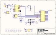
Schematic: Target InterfaceNOTE: RESISTORS ARE IN OHMS +/- 5a AND CAPACITORS ARE IN MICROFARADS UNLESSOTHERWISE NOTED. SEE BOM FOR ACTUAL VOLTAGE AND SPECIFICATION.3V3VADJ<str<strong>on</strong>g>JTAGulator</str<strong>on</strong>g>: Target InterfaceTITLE0.1uFC190.1uFC20P0P1P2P3P4P5P6P7P8P9P10P11P12P13P14P15P16P17P18P19P20P21P22P2312345P2TE 282834-5CH0CH1CH2CH312345P3TE 282834-512345P4TE 282834-512345P5TE 282834-512345P6TE 282834-5CH4CH5CH6CH7CH8CH9CH10CH11CH12CH13CH14CH15CH16CH17CH18CH19CH20CH21CH22CH23I/O11GND2I/O23I/O34VCC5I/O46U8NUP4302MR6VADJI/O11GND2I/O23I/O34VCC5I/O46U7NUP4302MR6VADJI/O11GND2I/O23I/O34VCC5I/O46U11NUP4302MR6VADJI/O11GND2I/O23I/O34VCC5I/O46U10NUP4302MR6VADJI/O11GND2I/O23I/O34VCC5I/O46U14NUP4302MR6VADJI/O11GND2I/O23I/O34VCC5I/O46U13NUP4302MR6VADJ3V3VADJ0.1uFC180.1uFC223V3VADJ0.1uFC170.1uFC2110kR10TXSOEVADJ3V3VADJ3V3VADJ3V3P[23...0]Diode limiters for input protecti<strong>on</strong>Vf must be < 0.5V to prevent damage to level translatorsVCCA
Propeller/Core• Completely custom, ground up design• 8 independent cogs @ 20 MIPS each• Code in Spin, ASM, or C*** INFORMATION: www.parallax.com/propeller/*** DISCUSSION FORUMS: http://forums.parallax.com*** OBJECT EXCHANGE: http://obex.parallax.com
Propeller/Core 2• Clock: DC to 128MHz (80MHz recommended)• Global (hub) memory: 32KB RAM, 32KB ROM• Cog memory: 2KB RAM each• GPIO: 32 @ 40mA sink/source per pin• Program code loaded from external EEPROM <strong>on</strong>power-up
Propeller/Core 3
Propeller/Core 4• Standard development using Propeller Tool &Parallax Serial Terminal (Windows)• Programmable via serial interface (usually inc<strong>on</strong>juncti<strong>on</strong> w/ USB-to-serial IC)
Propeller/Core 5
USB Interface• Allows for Propeller programming & UI• Powers <str<strong>on</strong>g>JTAGulator</str<strong>on</strong>g> from bus (5V)• FT232RL USB-to-Serial UART- Entire USB protocol handled <strong>on</strong>-<strong>chip</strong>- Host will recognize as a virtual serial port (Windows,OS X, Linux)• MIC2025 Power Distributi<strong>on</strong> Switch- Internal current limiting, thermal shutdown- Let the FT232 enumerate first (@ < 100mA), thenenable system load
USB Interface 2
Adjustable Target Voltage• PWM from Propeller- Duty cycle corresp<strong>on</strong>ds to output voltage (VADJ)- Look-up table for values in 0.1V increments• AD8655 Low Noise, Precisi<strong>on</strong> CMOS Amplifier- Single supply, rail-to-rail- 220mA output current (~150mA @ Vo = 1.2V-3.3V)- Voltage follower c<strong>on</strong>figurati<strong>on</strong> to serve as DAC buffer
Level Translati<strong>on</strong>• Allows 3.3V signals from Propeller to bec<strong>on</strong>verted to VADJ (1.2V-3.3V)• Prevents potential damage due to over-voltage<strong>on</strong> target device's unknown c<strong>on</strong>necti<strong>on</strong>s• TXS0108E Bidirecti<strong>on</strong>al Voltage-Level Translator- Designed for both open drain and push-pull interfaces- Internal pull-up resistors (40kΩ when driving low, 4kΩwhen high)- Automatic signal directi<strong>on</strong> detecti<strong>on</strong>- High-Z outputs when OE low -> will not interfere withtarget when not in use
Level Translati<strong>on</strong> 2
Input Protecti<strong>on</strong>• Prevent high voltages/spikes <strong>on</strong> unknown pinsfrom damaging <str<strong>on</strong>g>JTAGulator</str<strong>on</strong>g>• Diode limiter clamps input if needed• Vf must be < 0.5V to protect TXS0108Es
Input Protecti<strong>on</strong> 2• NUP4302MR6 Schottky Diode Array- Vf @ 1mA = 0.2V typ., 0.35V max.- Vf @ 10mA = 0.25V typ., 0.45V max.- Alternate: SD103ASDM
Bill-<str<strong>on</strong>g>of</str<strong>on</strong>g>-Materials<str<strong>on</strong>g>JTAGulator</str<strong>on</strong>g><str<strong>on</strong>g>JTAGulator</str<strong>on</strong>g>Bill-<str<strong>on</strong>g>of</str<strong>on</strong>g>-MaterialsHW B, Document 1.0, April 19, 2013Item Quantity Reference Manufacturer Manuf. Part # Distributor Distrib. Part # Descripti<strong>on</strong>1 2 C1, C2 Kemet C1206C103K5RACTU Digi-Key 399-1234-1-ND Capacitor, 0.01uF ceramic, 10%, 50V, X7R, 12062 14C3, C6, C9, C11, C12, C13, C14, C15,C17, C18, C19, C20, C21, C22 Kemet C1206C104K5RACTU Digi-Key 399-1249-1-ND Capacitor, 0.1uF ceramic, 10%, 50V, X7R, 12063 1 C4 Yageo CC1206KRX7R9BB102 Digi-Key 311-1170-1-ND Capacitor, 1000pF ceramic, 10%, 50V, X7R, 12064 1 C5 Yageo CC1206KRX7R9BB471 Digi-Key 311-1167-1-ND Capacitor, 470pF ceramic, 10%, 50V, X7R, 12065 1 C7 Kemet T491A106M016AS Digi-Key 399-3687-1-ND Capacitor, 10uF tantalum, 20%, 16V, size A6 2 C8, C10 Kemet T491A475K016AT Digi-Key 399-3697-1-ND Capacitor, 4.7uF tantalum, 10%, 16V, size A7 1 D1 Kingbright WP59EGW Digi-Key 754-1232-ND LED, Red/Green Bi-Color, T-1 3/4 (5mm)8 1 L1 TDK MPZ2012S221A Digi-Key 445-1568-1-ND Inductor, Ferrite Bead, 220R@100MHz, 3A, 08059 1 P1 Hirose Electric UX60-MB-5S8 Digi-Key H2960CT-ND C<strong>on</strong>nector, Mini-USB, 5-pin, SMT w/ PCB mount10 5 P2, P3, P4, P5, P6 TE C<strong>on</strong>nectivity 282834-5 Digi-Key A98336-ND C<strong>on</strong>nector, Terminal Block, 5-pin, side entry, 0.1” P11 3 P7, P8, P9 3M 961210-6404-AR Digi-Key 3M9460-ND Header, Dual row, Vertical header, 2x5-pin, 0.1” P12 1 Q1 Fairchild MMBT3904 Digi-Key MMBT3904FSCT-ND Transistor, NPN, 40V, 200mA, SOT23-313 5 R1, R2, R3, R4, R10 Any Any Digi-Key P10KECT-ND Resistor, 10k, 5%, 1/4W, 120614 1 R5 Any Any Digi-Key P470ECT-ND Resistor, 470 ohm, 5%, 1/4W, 120615 1 R6 Any Any Digi-Key P270ECT-ND Resistor, 270 ohm, 5%, 1/4W, 120616 1 R7 Any Any Digi-Key P18.0KFCT-ND Resistor, 18k, 1%, 1/4W, 120617 1 R8 Any Any Digi-Key P8.20KFCT-ND Resistor, 8.2k, 1%, 1/4W, 120618 1 R9 Any Any Digi-Key P100KECT-ND Resistor, 100k, 5%, 1/4W, 120619 3 R11, R12, R13 Bourns 4816P-1-102LF Digi-Key 4816P-1-102LFCT-ND Resistor, Array, 8 isolated, 1k, 2%, 1/6W, SOIC1620 1 SW1 C&K KSC201JLFS Digi-Key 401-1756-1-ND Switch, SPST, Momentary, 120gf, 6.2 x 6.2mm, J-Lead21 1 U1 FTDI FT232RL-REEL Digi-Key 768-1007-1-ND IC, USB-to-UART Bridge, SSOP2822 1 U2 Parallax P8X32A-Q44 Digi-Key P8X32A-Q44-ND IC, Microc<strong>on</strong>troller, Propeller, LQFP4423 1 U3 Micrel MIC2025-2YM Digi-Key 576-1058-ND IC, Power Distributi<strong>on</strong> Switch, Single-channel, SOIC824 1 U4 Micro<strong>chip</strong> 24LC512-I/SN Digi-Key 24LC512-I/SN-ND IC, Memory, Serial EEPROM, 64KB, SOIC825 1 U5 Analog Devices AD8655ARZ Digi-Key AD8655ARZ-ND IC, Op. Amp., CMOS, Rail-to-rail, 220mA Iout, SOIC826 1 U6 ST Microelectr<strong>on</strong>ics LD1117S33CTR Digi-Key 497-1241-1-ND IC, Voltage Regulator, LDO, 3.3V@800mA, SOT22327 6 U7, U8, U10, U11, U13, U14 ON Semic<strong>on</strong>ductor NUP4302MR6T1G Digi-Key NUP4302MR6T1GOSCT-ND IC, Schottky Diode Array, 4 channel, TSOP628 3 U9, U12, U15 Texas Instruments TXS0108EPWR Digi-Key 296-23011-1-ND IC, Level Translator, Bi-directi<strong>on</strong>al, TSSOP2029 1 Y1 ECS ECS-50-18-4XEN Digi-Key XC1738-ND Crystal, 5.0MHz, 18pF, HC49/US30 1 PCB Any JTAG B N/A N/A PCB, Fabricati<strong>on</strong>• All comp<strong>on</strong>ents from Digi-Key• Total cost per unit = $50.73
Firmware
Source Tree
Cogs• Spin Interpreter (Cog 0)• Parallax Serial Terminal (ser)• Real Random (rr)• JDCogSerial (uart)
Propeller Resources
General Commands• Set target system voltage (V) (1.2V-3.3V)• Read all channels (R)• Write all channels (W)• Print available commands (H)
JTAG Commands• Identify JTAG pinout via IDCODE scan (I)• Identify JTAG pinout via BYPASS scan (B)• Get Device IDs (D) (w/ known pinout)• Test BYPASS (T) (w/ known pinout)
IDCODE Scan• 32-bit Device ID (if available) is in the DR <strong>on</strong>TAP reset or IC power-up- Otherwise, TAP will reset to BYPASS (LSB = 0)- Can simply enter Shift-DR state and clock out <strong>on</strong> TDO- TDI not required/used during IDCODE acquisiti<strong>on</strong>LSB
IDCODE Scan 2• Device ID values vary with part/family/vendor- Locate in data sheets, BSDL files, reference code,etc.• Manufacturer ID provided by JEDEC- Each manufacturer assigned a unique identifier- Can use to help validate that proper IDCODE wasretrieved- http://www.jedec.org/standards-documents/results/jep106
IDCODE Scan 3• Ask user for number <str<strong>on</strong>g>of</str<strong>on</strong>g> channels to use• For every possible pin permutati<strong>on</strong> (except TDI)- Set unused channels to output high (in case <str<strong>on</strong>g>of</str<strong>on</strong>g> anyactive low reset pins)- C<strong>on</strong>figure JTAG pins to use <strong>on</strong> the Propeller- Reset the TAP- Try to get the Device ID by reading the DR- If Device ID is 0xFFFFFFFF or if bit 0 != 1, ignore- Otherwise, display potentially valid JTAG pinout
BYPASS Scan• In BYPASS, data shifted into TDI is received <strong>on</strong>TDO delayed by <strong>on</strong>e clock cycle
BYPASS Scan 2• Can determine how many devices (if any)are in the chain via "blind interrogati<strong>on</strong>"- Force device(s) into BYPASS (IR <str<strong>on</strong>g>of</str<strong>on</strong>g> all 1s)- Send 1s to fill DRs- Send a 0 and count until it is output <strong>on</strong> TDO
BYPASS Scan 3• Ask user for number <str<strong>on</strong>g>of</str<strong>on</strong>g> channels to use• For every possible pin permutati<strong>on</strong>- Set unused channels to output high (in case <str<strong>on</strong>g>of</str<strong>on</strong>g> anyactive low reset pins)- C<strong>on</strong>figure JTAG pins to use <strong>on</strong> the Propeller- Reset the TAP- Perform blind interrogati<strong>on</strong>- If number <str<strong>on</strong>g>of</str<strong>on</strong>g> detected devices > 0, display potentiallyvalid JTAG pinout
JTAG: Examples
DEFCON 17 Badge• Freescale MC56F8006 Digital Signal C<strong>on</strong>troller- ID = 0x01C0601D- www.bsdl.info/details.htm?sid=e82c74686c7522e888ca59b002289d77MSBLSB┌───────┬───────────────┬─────────────┬─────────────────┬─────────────────┬───────┐│ Ver. │ Design Center │ Core Number | Chip Derivative | Manufacturer ID │ Fixed │└───────┴───────────────┴─────────────┴─────────────────┴─────────────────┴───────┘31...28 27...22 21...17 16...12 11...1 00000 000111 00000 (DSP56300) 00110 00000001110 (0x0E) 1
Linksys WRT54G v1.1• Broadcom BCM4702 (also c<strong>on</strong>tains BCM4306)- ID = 0x0471017F- https://github.com/notch/tjtag/blob/master/tjtag.cMSBLSB┌───────┬──────────────────────────────────┬────────────────────────┬───────┐│ Ver. │ Part Number | Manufacturer ID │ Fixed │└───────┴──────────────────────────────────┴────────────────────────┴───────┘31...28 27...12 11...1 00000 0100011100010000 (BCM4702 rev. 1) 00010111111 (0xBF) 1*** www.jtagtest.com/pinouts/wrt54
D-Link DWL-900AP+• Samsung S3C4510B01-QER0 CPU (ARM7TDMI)- ID = 0x1F0F0F0F- http://pdf1.alldatasheet.com/datasheet-pdf/view/37744/SAMSUNG/S3C4510B.html (Appendix A)*** www.jtagtest.com/pinouts/arm14
D-Link DWL-900AP+ 2• Lattice ispMACH iM4A3-32 CPLD (TQFP-48)- ID = 0x17437157- www.latticesemi.com/lit/docs/bsdl/mach4a3/m4a032t8l_isc.bsm
Samsung SCH-i910• Marvell PXA312 (Intel XScale/ARM5)- ID = 0x2E649013- http://docs.toradex.com/100197-colibri-arm-sompxa3xx-dm-vol-1.pdf(Table 9)- TCK = 5 (Blue), TMS = 4 (Pink), TDI = 3 (Grey), TDO = 6(Orange), GND = 8 (Black)• JTAG disabled when external power supplied orph<strong>on</strong>e is "<strong>on</strong>" via battery
BlackBerry 7250• Qualcomm MSM6500 <strong>chip</strong>set (ARM926EJ-S)- ID = 0x6003C0E1- VCC = 2.6VMSBLSB┌───────┬──────────────────────────────────┬────────────────────────┬───────┐│ Ver. │ Part Number | Manufacturer ID │ Fixed │└───────┴──────────────────────────────────┴────────────────────────┴───────┘31...28 27...12 11...1 00110 0000000000111100 00001110000 (0x70) 1
BlackBerry 7290• AD6529 "Hermes" DSP (ARM7TDMI)• AD6521 "Pegasus" Analog Baseband- IDs = 0x027831CB and 0x027B51CB- Unknown which ID is for which device- TDO1 = Only <strong>on</strong>e device- TDO2 = Both devices in the chainMSBLSB┌───────┬──────────┬────────────┬────────┬───────────────┬─────────────────┬───────┐│ Ver. │ Core ID │ Capability | Family | Device Number | Manufacturer ID │ Fixed │└───────┴──────────┴────────────┴────────┴───────────────┴─────────────────┴───────┘31...28 27 26...24 23...20 19...12 11...1 00000 0 (ARM) 010 (Reserved) 0111 (ARM7) 10000011 00011100101 (0xE5) 10000 0 (ARM) 010 (Reserved) 0111 (ARM7) 01010001 00011100101 (0xE5) 1*** http://infocenter.arm.com/help/topic/com.arm.doc.dai0099c/DAI0099C_core_type_rev_id.pdf
BlackBerry 7290 2
UART Commands• Identify UART pinout (U)• UART pass through (P) (w/ known pinout)
UART Scan• Ask user for desired output string (up to 16bytes)• Ask user for number <str<strong>on</strong>g>of</str<strong>on</strong>g> channels to use• For every possible pin permutati<strong>on</strong>- C<strong>on</strong>figure UART pins to use <strong>on</strong> the Propeller- Set baud rate- Send user string- Wait to receive data (20ms maximum per byte)- If any bytes received, display potentially valid UARTpinout and data (up to 16 bytes)
UART Scan 2• 8 data bits, no parity, 1 stop bit (8N1)• Baud rates stored in look-up table- 75, 110, 150, 300, 900, 1200, 1800, 2400, 3600,4800, 7200, 9600, 14400, 19200, 28800, 31250,38400, 57600, 76800, 115200, 153600, 230400,250000, 307200
UART Scan 3
UART: Examples
Linksys WRT54G v2 rXH (w/ DD-WRT)• Broadcom BCM4712- ID = 0x1471217F- https://github.com/notch/tjtag/blob/master/tjtag.c- UART: JP1 (TXD = 4, RXD = 6) @ 115200, 8N1*** www.jtagtest.com/pinouts/wrt54
Scan Timing• IDCODE- TDI ignored since we're <strong>on</strong>ly shifting data out <str<strong>on</strong>g>of</str<strong>on</strong>g> DR- ~264 permutati<strong>on</strong>s/sec<strong>on</strong>d• BYPASS- Many bits/permutati<strong>on</strong> needed to account formultiple devices in chain and varying IR lengths- ~13.37 permutati<strong>on</strong>s/sec<strong>on</strong>d# <str<strong>on</strong>g>of</str<strong>on</strong>g> IDCODE IDCODE BYPASS BYPASSChannels Permutati<strong>on</strong>s (mm:ss) Permutati<strong>on</strong>s (mm:ss)4 24 < 00:01 24 00:028 336 00:02 1680 02:0516 3360 00:13 43680 54:2724 12144 00:46 255024 317:54
Scan Timing 2• UART- Only need to locate two pins (TXD/RXD)- 24 baud rates/permutati<strong>on</strong>- ~1 permutati<strong>on</strong>/sec<strong>on</strong>d# <str<strong>on</strong>g>of</str<strong>on</strong>g> UART TimeChannels Permutati<strong>on</strong>s (mm:ss)4 12 00:128 56 00:5716 240 4:0424 552 9:22
Dem<strong>on</strong>strati<strong>on</strong>
Possible Limitati<strong>on</strong>s• Could cause target to behave abnormally due to"fuzzing" unknown pins• OCD interface isn't being properly enabled- N<strong>on</strong>-standard c<strong>on</strong>figurati<strong>on</strong>- Password protected- System expects defined reset sequence or pin setting• OCD interface is physically disc<strong>on</strong>nected- Cut traces, missing jumpers/0 ohm resistors• No OCD interface exists*** Additi<strong>on</strong>al reverse engineering will be necessaryto determine the problem or discover pinout
Future Work• Add support for other interfaces- TI Spy-Bi-Wire, ARM Serial Wire Debug,Micro<strong>chip</strong> ICSP, Atmel AVR ISP
Other Uses• Propeller development board• Logic analyzer• Inter-<strong>chip</strong> communicati<strong>on</strong>/probing ala BusPirate or GoodFET• ???
Get It• www.jtagulator.com*** Schematics, source code, BOM, block diagram,Gerber plots, photos, other engineering documentati<strong>on</strong>• www.parallax.com*** Assembled units, bare boards, accessories
A Poem
The End.