Modeling and Simulation of Non-ideal Buck Converter in DCM
Modeling and Simulation of Non-ideal Buck Converter in DCM
Modeling and Simulation of Non-ideal Buck Converter in DCM

Create successful ePaper yourself
Turn your PDF publications into a flip-book with our unique Google optimized e-Paper software.
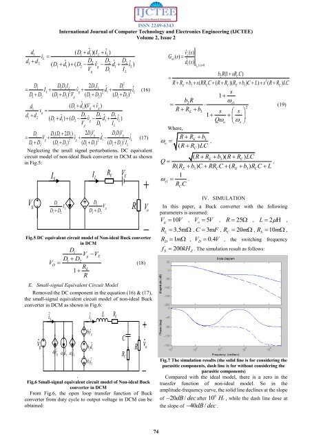
ISSN 2249-6343International Journal <strong>of</strong> Computer Technology <strong>and</strong> Electronics Eng<strong>in</strong>eer<strong>in</strong>g (IJCTEE)Volume 2, Issue 2d ( D dˆ)( I iˆ)i d( D dˆ ) ( D v dˆ iˆ)1 1 1 L LL1dD22D2 D2ˆ112g1LVgD1ILD D D I 2D I ˆ D ˆD D D D V D D D Dd1d d21 1 2 L2 L1I ˆLv2 gd2 1i2 L12(12) g(12) (12)1 2( D ˆ ˆ1d1)( Vgvg)vg( ˆ D D) ( ˆ ˆ DD d D v d iˆ)2 2 21 1 2 g 1 LVgD1ILD D ( D 2 D ) 2D VˆˆD D V V v d iˆD D D D D D D D I1 1 1 22 g1 2 gg 2 g 2 12 L12(12) (12) (12)L(16)(17)Neglect<strong>in</strong>g the small signal perturbations, DC equivalentcircuit model <strong>of</strong> non-<strong>ideal</strong> <strong>Buck</strong> converter <strong>in</strong> <strong>DCM</strong> as shown<strong>in</strong> Fig.5:I I RLE V ESV gD1D D12I LD1D DFig.5 DC equivalent circuit model <strong>of</strong> <strong>Non</strong>-<strong>ideal</strong> <strong>Buck</strong> converter<strong>in</strong> <strong>DCM</strong>VODD1Vg VE1D2RE1RE. Small-signal Equivalent Circuit Model12V gR(18)Removed the DC component <strong>in</strong> the equation (16) & (17),the small-signal equivalent circuit model <strong>of</strong> non-<strong>ideal</strong> <strong>Buck</strong>converter <strong>in</strong> <strong>DCM</strong> as shown <strong>in</strong> Fig.6:vˆgî Savˆga ˆd 21 1a iˆ3 LîLb vˆ1 gb 2 ˆd 1b iˆ3 LFig.6 Small-signal equivalent circuit model <strong>of</strong> <strong>Non</strong>-<strong>ideal</strong> <strong>Buck</strong>converter <strong>in</strong> <strong>DCM</strong>From Fig.6, the open loop transfer function <strong>of</strong> <strong>Buck</strong>converter from duty cycle to output voltage <strong>in</strong> <strong>DCM</strong> can beobta<strong>in</strong>ed:LR ECR CRV ovˆoovˆ () sG () s vd odˆ 1 () svˆ g ( s) 0b2R(1 sRCC)2E 3(C(C)(E 3) ) (C)R R b s RR C R R R b C L s R R LCs1bR2z1 (19)2R REb3s s 1 QooWhere,R REb3( R R ) LCC,( R RE b3)( R RC)LCQ R ( RE b3) C RRC C ( RE b3)RC C ,L1z1 .RCCIV. SIMULATIONIn this paper, a <strong>Buck</strong> converter with the follow<strong>in</strong>gparameters is assumed:V 10V, V 5V, R 25 , L 2 ,goR 3.5m , C 3mF, R 20m , R 10m ,RfLDS1m , V 0.4V 200kHZDC, the switch<strong>in</strong>g frequency. The simulation result as follows:Fig.7 The simulation results (the solid l<strong>in</strong>e is for consider<strong>in</strong>g theparasitic components, dash l<strong>in</strong>e is for without consider<strong>in</strong>g theparasitic components)Compared with the <strong>ideal</strong> model, there is a zero <strong>in</strong> thetransfer function <strong>of</strong> non-<strong>ideal</strong> model. So <strong>in</strong> theamplitude-frequency curve, the solid l<strong>in</strong>e decl<strong>in</strong>es at the slope6<strong>of</strong> 20 dB / dec after 10 H z , while the dash l<strong>in</strong>e dose atthe slope <strong>of</strong> 40 dB / dec .S74