Modeling and Simulation of Non-ideal Buck Converter in DCM
Modeling and Simulation of Non-ideal Buck Converter in DCM
Modeling and Simulation of Non-ideal Buck Converter in DCM

Create successful ePaper yourself
Turn your PDF publications into a flip-book with our unique Google optimized e-Paper software.
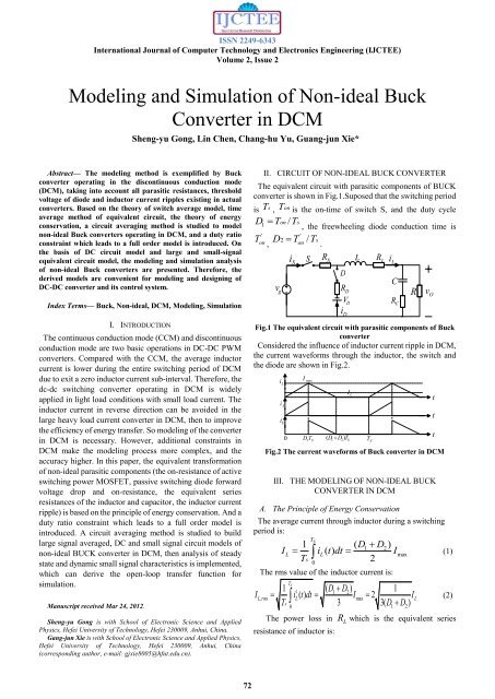
ISSN 2249-6343International Journal <strong>of</strong> Computer Technology <strong>and</strong> Electronics Eng<strong>in</strong>eer<strong>in</strong>g (IJCTEE)Volume 2, Issue 2<strong>Model<strong>in</strong>g</strong> <strong>and</strong> <strong>Simulation</strong> <strong>of</strong> <strong>Non</strong>-<strong>ideal</strong> <strong>Buck</strong><strong>Converter</strong> <strong>in</strong> <strong>DCM</strong>Sheng-yu Gong, L<strong>in</strong> Chen, Chang-hu Yu, Guang-jun Xie*Abstract— The model<strong>in</strong>g method is exemplified by <strong>Buck</strong>converter operat<strong>in</strong>g <strong>in</strong> the discont<strong>in</strong>uous conduction mode(<strong>DCM</strong>), tak<strong>in</strong>g <strong>in</strong>to account all parasitic resistances, thresholdvoltage <strong>of</strong> diode <strong>and</strong> <strong>in</strong>ductor current ripples exist<strong>in</strong>g <strong>in</strong> actualconverters. Based on the theory <strong>of</strong> switch average model, timeaverage method <strong>of</strong> equivalent circuit, the theory <strong>of</strong> energyconservation, a circuit averag<strong>in</strong>g method is studied to modelnon-<strong>ideal</strong> <strong>Buck</strong> converters operat<strong>in</strong>g <strong>in</strong> <strong>DCM</strong>, <strong>and</strong> a duty ratioconstra<strong>in</strong>t which leads to a full order model is <strong>in</strong>troduced. Onthe basis <strong>of</strong> DC circuit model <strong>and</strong> large <strong>and</strong> small-signalequivalent circuit model, the model<strong>in</strong>g <strong>and</strong> simulation analysis<strong>of</strong> non-<strong>ideal</strong> <strong>Buck</strong> converters are presented. Therefore, thederived models are convenient for model<strong>in</strong>g <strong>and</strong> design<strong>in</strong>g <strong>of</strong>DC-DC converter <strong>and</strong> its control system.Index Terms— <strong>Buck</strong>, <strong>Non</strong>-<strong>ideal</strong>, <strong>DCM</strong>, <strong>Model<strong>in</strong>g</strong>, <strong>Simulation</strong>I. INTRODUCTIONThe cont<strong>in</strong>uous conduction mode (CCM) <strong>and</strong> discont<strong>in</strong>uousconduction mode are two basic operations <strong>in</strong> DC-DC PWMconverters. Compared with the CCM, the average <strong>in</strong>ductorcurrent is lower dur<strong>in</strong>g the entire switch<strong>in</strong>g period <strong>of</strong> <strong>DCM</strong>due to exit a zero <strong>in</strong>ductor current sub-<strong>in</strong>terval. Therefore, thedc-dc switch<strong>in</strong>g converter operat<strong>in</strong>g <strong>in</strong> <strong>DCM</strong> is widelyapplied <strong>in</strong> light load conditions with small load current. The<strong>in</strong>ductor current <strong>in</strong> reverse direction can be avoided <strong>in</strong> thelarge heavy load current converter <strong>in</strong> <strong>DCM</strong>, then to improvethe efficiency <strong>of</strong> energy transfer. So model<strong>in</strong>g <strong>of</strong> the converter<strong>in</strong> <strong>DCM</strong> is necessary. However, additional constra<strong>in</strong>ts <strong>in</strong><strong>DCM</strong> make the model<strong>in</strong>g process more complex, <strong>and</strong> theaccuracy higher. In this paper, the equivalent transformation<strong>of</strong> non-<strong>ideal</strong> parasitic components (the on-resistance <strong>of</strong> activeswitch<strong>in</strong>g power MOSFET, passive switch<strong>in</strong>g diode forwardvoltage drop <strong>and</strong> on-resistance, the equivalent seriesresistances <strong>of</strong> the <strong>in</strong>ductor <strong>and</strong> capacitor, the <strong>in</strong>ductor currentripple) is based on the pr<strong>in</strong>ciple <strong>of</strong> energy conservation. And aduty ratio constra<strong>in</strong>t which leads to a full order model is<strong>in</strong>troduced. A circuit averag<strong>in</strong>g method is studied to buildlarge signal averaged, DC <strong>and</strong> small signal circuit models <strong>of</strong>non-<strong>ideal</strong> BUCK converter <strong>in</strong> <strong>DCM</strong>, then analysis <strong>of</strong> steadystate <strong>and</strong> dynamic small signal characteristics is implemented,which can derive the open-loop transfer function forsimulation.Manuscript received Mar 24, 2012.Sheng-yu Gong is with School <strong>of</strong> Electronic Science <strong>and</strong> AppliedPhysics, Hefei University <strong>of</strong> Technology, Hefei 230009, Anhui, Ch<strong>in</strong>a.Gang-jun Xie is with School <strong>of</strong> Electronic Science <strong>and</strong> Applied Physics,Hefei University <strong>of</strong> Technology, Hefei 230009, Anhui, Ch<strong>in</strong>a(correspond<strong>in</strong>g author, e-mail: gjxie8005@hfut.edu.cn).II. CIRCUIT OF NON-IDEAL BUCK CONVERTERThe equivalent circuit with parasitic components <strong>of</strong> BUCKconverter is shown <strong>in</strong> Fig.1.Suposed that the switch<strong>in</strong>g periodis T s , Tonis the on-time <strong>of</strong> switch S, <strong>and</strong> the duty cycleD T T1 on /'Ton ,sD T Tv g'2on/ siS, the freewheel<strong>in</strong>g diode conduction time isS.RSDR DV Di DFig.1 The equivalent circuit with parasitic components <strong>of</strong> <strong>Buck</strong>converterConsidered the <strong>in</strong>fluence <strong>of</strong> <strong>in</strong>ductor current ripple <strong>in</strong> <strong>DCM</strong>,the current waveforms through the <strong>in</strong>ductor, the switch <strong>and</strong>the diode are shown <strong>in</strong> Fig.2.i Li Si DImax0 D 1T S( D 1D2) TSI LLT SRLi LCR CRvOFig.2 The current waveforms <strong>of</strong> <strong>Buck</strong> converter <strong>in</strong> <strong>DCM</strong>III. THE MODELING OF NON-IDEAL BUCKCONVERTER IN <strong>DCM</strong>A. The Pr<strong>in</strong>ciple <strong>of</strong> Energy ConservationThe average current through <strong>in</strong>ductor dur<strong>in</strong>g a switch<strong>in</strong>gperiod is:T1S( D1D2)IL iL()t dt ImaxTs20(1)The rms value <strong>of</strong> the <strong>in</strong>ductor current is:T1S2( D1D2)1L, rmsL( ) max 2LTs3 3( D01D2)(2)I i t dt I IThe power loss <strong>in</strong>resistance <strong>of</strong> <strong>in</strong>ductor is:RLwhich is the equivalent seriesttt72
ISSN 2249-6343International Journal <strong>of</strong> Computer Technology <strong>and</strong> Electronics Eng<strong>in</strong>eer<strong>in</strong>g (IJCTEE)Volume 2, Issue 2d ( D dˆ)( I iˆ)i d( D dˆ ) ( D v dˆ iˆ)1 1 1 L LL1dD22D2 D2ˆ112g1LVgD1ILD D D I 2D I ˆ D ˆD D D D V D D D Dd1d d21 1 2 L2 L1I ˆLv2 gd2 1i2 L12(12) g(12) (12)1 2( D ˆ ˆ1d1)( Vgvg)vg( ˆ D D) ( ˆ ˆ DD d D v d iˆ)2 2 21 1 2 g 1 LVgD1ILD D ( D 2 D ) 2D VˆˆD D V V v d iˆD D D D D D D D I1 1 1 22 g1 2 gg 2 g 2 12 L12(12) (12) (12)L(16)(17)Neglect<strong>in</strong>g the small signal perturbations, DC equivalentcircuit model <strong>of</strong> non-<strong>ideal</strong> <strong>Buck</strong> converter <strong>in</strong> <strong>DCM</strong> as shown<strong>in</strong> Fig.5:I I RLE V ESV gD1D D12I LD1D DFig.5 DC equivalent circuit model <strong>of</strong> <strong>Non</strong>-<strong>ideal</strong> <strong>Buck</strong> converter<strong>in</strong> <strong>DCM</strong>VODD1Vg VE1D2RE1RE. Small-signal Equivalent Circuit Model12V gR(18)Removed the DC component <strong>in</strong> the equation (16) & (17),the small-signal equivalent circuit model <strong>of</strong> non-<strong>ideal</strong> <strong>Buck</strong>converter <strong>in</strong> <strong>DCM</strong> as shown <strong>in</strong> Fig.6:vˆgî Savˆga ˆd 21 1a iˆ3 LîLb vˆ1 gb 2 ˆd 1b iˆ3 LFig.6 Small-signal equivalent circuit model <strong>of</strong> <strong>Non</strong>-<strong>ideal</strong> <strong>Buck</strong>converter <strong>in</strong> <strong>DCM</strong>From Fig.6, the open loop transfer function <strong>of</strong> <strong>Buck</strong>converter from duty cycle to output voltage <strong>in</strong> <strong>DCM</strong> can beobta<strong>in</strong>ed:LR ECR CRV ovˆoovˆ () sG () s vd odˆ 1 () svˆ g ( s) 0b2R(1 sRCC)2E 3(C(C)(E 3) ) (C)R R b s RR C R R R b C L s R R LCs1bR2z1 (19)2R REb3s s 1 QooWhere,R REb3( R R ) LCC,( R RE b3)( R RC)LCQ R ( RE b3) C RRC C ( RE b3)RC C ,L1z1 .RCCIV. SIMULATIONIn this paper, a <strong>Buck</strong> converter with the follow<strong>in</strong>gparameters is assumed:V 10V, V 5V, R 25 , L 2 ,goR 3.5m , C 3mF, R 20m , R 10m ,RfLDS1m , V 0.4V 200kHZDC, the switch<strong>in</strong>g frequency. The simulation result as follows:Fig.7 The simulation results (the solid l<strong>in</strong>e is for consider<strong>in</strong>g theparasitic components, dash l<strong>in</strong>e is for without consider<strong>in</strong>g theparasitic components)Compared with the <strong>ideal</strong> model, there is a zero <strong>in</strong> thetransfer function <strong>of</strong> non-<strong>ideal</strong> model. So <strong>in</strong> theamplitude-frequency curve, the solid l<strong>in</strong>e decl<strong>in</strong>es at the slope6<strong>of</strong> 20 dB / dec after 10 H z , while the dash l<strong>in</strong>e dose atthe slope <strong>of</strong> 40 dB / dec .S74
ISSN 2249-6343International Journal <strong>of</strong> Computer Technology <strong>and</strong> Electronics Eng<strong>in</strong>eer<strong>in</strong>g (IJCTEE)Volume 2, Issue 246In the phase-frequency curve, from 10 H z to10 H z , the0 0phase marg<strong>in</strong> <strong>of</strong> non-<strong>ideal</strong> model rises from -90 to 0 ,0while the <strong>ideal</strong> model rema<strong>in</strong>s -90 . The simulation resultshows that consider<strong>in</strong>g the parasitic components <strong>and</strong> the dutycycle constra<strong>in</strong>t, the high-frequency performance <strong>of</strong> BUCKconverter is more accurate.V. CONCLUSIONIn the paper, the equivalent circuit with parasiticcomponents <strong>of</strong> <strong>Buck</strong> converter agrees with the theoreticalanalysis well, the simulation result confirms the validity <strong>of</strong>this model<strong>in</strong>g method <strong>in</strong> <strong>DCM</strong>; the full order model reflectsthe actual converter characteristics more accurately, <strong>in</strong>particular high-frequency performance. It is very importantfor improv<strong>in</strong>g the accuracy <strong>of</strong> the model.ACKNOWLEDGMENTThis work was supported by the Intercollegiate Key Project<strong>of</strong> Nature Science <strong>of</strong> Anhui Prov<strong>in</strong>ce under Grant No.KJ2011A213.REFERENCES[1] Robert W. Erickson, Dragan Maksimovic. Fundamentals <strong>of</strong> PowerElectronics (Second Edition). Kluwer Academic Publishers, 2001.[2] J Sun, D. M. Mitchell. Averaged <strong>Model<strong>in</strong>g</strong> <strong>of</strong> PWM <strong>Converter</strong>sOperat<strong>in</strong>g <strong>in</strong> Discont<strong>in</strong>uous Conduction Mode, IEEE Trans. PowerElectronics, Vol.16, No.4, 2001, 482-492.[3] D. Maksimovic, A. M. Stankovic. <strong>Model<strong>in</strong>g</strong> <strong>and</strong> <strong>Simulation</strong> <strong>of</strong> PowerElectronic <strong>Converter</strong>s, Proc <strong>of</strong> the IEEE, Vol.89, No.6, 2001, 898-912.[4] Zhang Weip<strong>in</strong>g. <strong>Model<strong>in</strong>g</strong> <strong>and</strong> Controll<strong>in</strong>g <strong>of</strong> Switch<strong>in</strong>g <strong>Converter</strong>.Ch<strong>in</strong>a Power Press, 2006.[5] Hou Zhenyi. Technology <strong>and</strong> Applications <strong>of</strong> DC Switch<strong>in</strong>g PowerSupply. Electronic Industry Press, 2006.[6] Ou Yang Changdi. <strong>Model<strong>in</strong>g</strong> Analysis <strong>and</strong> <strong>Simulation</strong> <strong>of</strong> DC-DCSwitch<strong>in</strong>g <strong>Converter</strong>. Aeronautics <strong>and</strong> Astronautics <strong>of</strong> Nanj<strong>in</strong>gUniversity, PhD thesis, 2004.[7] Cheng X<strong>in</strong>. <strong>Model<strong>in</strong>g</strong> <strong>and</strong> <strong>Simulation</strong> <strong>of</strong> <strong>Non</strong>-<strong>ideal</strong> DC-DC <strong>Converter</strong>s.Hefei University <strong>of</strong> Technology, Master thesis, 2009.[8] Xu Huifang. <strong>Model<strong>in</strong>g</strong> <strong>and</strong> Controll<strong>in</strong>g <strong>of</strong> Current Program Mode<strong>Non</strong>-<strong>ideal</strong> <strong>Buck</strong> <strong>Converter</strong>. Hefei University <strong>of</strong> Technology, Masterthesis, 2011.75