Dispersion Compensation for High Speed Optical ... - MIT Publications
Dispersion Compensation for High Speed Optical ... - MIT Publications
Dispersion Compensation for High Speed Optical ... - MIT Publications

You also want an ePaper? Increase the reach of your titles
YUMPU automatically turns print PDFs into web optimized ePapers that Google loves.
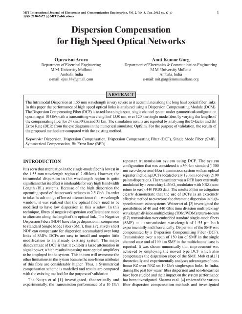
<strong>MIT</strong> International Journal of Electronics and Communication Engineering, Vol. 2, No. 1, Jan. 2012 pp. (1-4) 1ISSN 2230-7672 (c) <strong>MIT</strong> <strong>Publications</strong><strong>Dispersion</strong> <strong>Compensation</strong><strong>for</strong> <strong>High</strong> <strong>Speed</strong> <strong>Optical</strong> NetworksOjuswisni AroraDepartment of Electrical EngineeringM.M. University MullanaAmbala, Indiae-mail: ojus.88@gmail.comAmit Kumar GargDepartment of Electronics & Communication EngineeringM.M. University MullanaAmbala, Indiae-mail: mit.garg@mmumullana.orgABSTRACTThe Intramodal <strong>Dispersion</strong> at 1.55 mm wavelength is very severe as it accumulates along the long haul optical fiber links.In this paper the per<strong>for</strong>mance of high speed optical links is analyzed using a <strong>Dispersion</strong> Compensating Module (DCM).The <strong>Dispersion</strong> Compensating Fiber (DCF) is tested <strong>for</strong> a single span, single channel system under symmetrical configurationoperating at 10 Gb/s with a transmitting wavelength of 1550 nm, over 120 km single mode fibre, by varying the lengths ofthe compensating fiber <strong>for</strong> 24 km,30 km and 35 km. The simulation results are reported by analyzing the Q-factor and BitError Rate (BER) from the eye diagrams in the numerical simulator, OptSim. For the purpose of validation, the results ofthe proposed method are compared with the existing method.Keywords: <strong>Dispersion</strong>, <strong>Dispersion</strong> <strong>Compensation</strong>, <strong>Dispersion</strong> Compensating Fiber (DCF), Single Mode Fiber (SMF),Symmetrical <strong>Compensation</strong>, Bit Error Rate (BER).INTRODUCTIONIt is seen that attenuation in the single-mode fiber is lowest inthe 1.55 mm wavelength region (0.2 dB/km). However, theintramodal dispersion in this wavelength region is quitesignificant that its effect is intolerable <strong>for</strong> very high BandwidthLength (BL) systems. Because of the high dispersion theoperating speed of the network reduces to 2.5 Gb/s. In orderto take the advantage of lowest attenuation at this wavelengthwindow, it was realized that the optical fibers need to bemodified to have low dispersion in this window. In thistechnique, fibres of negative dispersion coefficient are madeto alternate along the length of the optical link. The Negative<strong>Dispersion</strong> Fibers (NDF) have a large dispersion in comparisonto standard Single Mode Fiber (SMF), thus a relatively shortNDF can compensate <strong>for</strong> dispersion accumulated over longlinks of SMFs. DCFs are easy to install and require littlemodification to an already existing system. The majordisadvantage of DCF is that it exhibits a large attenuation insignal power, which results into using more optical amplifiersto be employed in the system. This in turn will overcome theother limitations in the system because the non-linear attributesof this fibre are considerably higher. Thus, a Symmetricalcompensation scheme is modelled and results are comparedwith the existing method <strong>for</strong> the purpose of validation.The Nutys et al.[1] investigated, theoretically andexperimentally, the transmission per<strong>for</strong>mance of a 10 Gb/srepeater transmission system using DCF. The systemconfiguration that was considered is a 360 km standard (1300nm zero-dispersion) fiber transmission system with an opticalrepeater including DCFs located every 120 km (or every 2100ps/nm dispersion). The transmitter was a DFB laser externallymodulated by a zero-chirp LiNbO 3modulator with NRZ (nonreturnto zero), 440 PRBS data. The results of this investigationclearly demonstrate that the use of DCFs is an extremelyeffective method to overcome the chromatic dispersion in highspeedtransmission systems. Weinert et al. [2] investigated thepossibilities of 40 and 440 Gb/s time division multiplexing/wavelength division multiplexing (TDM/WDM) return-to-zero(RZ) transmission over embedded standard single-mode fibers(SMF) at a transmission wavelength of 1.55 µm bothexperimentally and theoretically. <strong>Dispersion</strong> of the SMF wascompensated by a <strong>Dispersion</strong> Compensating Fiber (DCF).Transmission over a span of 150 km of SMF in the singlechannel case and of 100 km SMF in the multichannel case isreported. It was shown numerically that improvement wasachieved by employing the newest type DCF which alsocompensates the dispersion slope of the SMF. Mob et al.[3]theoretically and experimentally analyses advantages of nonlinearRZ over NRZ on 10 Gb/s single-span links. In India,during the past few years’ fiber dispersion and non-linearitieshave been studied and their impact on the system per<strong>for</strong>mancehas been investigated. Sharma et al. [4] reviewed the variousfiber dispersion compensation methods and investigated
<strong>MIT</strong> International Journal of Electronics and Communication Engineering, Vol. 2, No. 1, Jan. 2012 pp. (1-4) 2ISSN 2230-7672 (c) <strong>MIT</strong> <strong>Publications</strong>techniques <strong>for</strong> compensation of dispersion by differential delaymethod including the impact of higher order dispersion termsKaler et al. [5] discussed the limitations due to Group Velocity<strong>Dispersion</strong> (GVD) on transmission distance, bit rate and laserlinewidth including the higher order dispersion effects. Thepower penalty analysis <strong>for</strong> different realistic weight functions<strong>for</strong> combating the pulse broadening effects of group-velocitydispersion in a fiber-optic communication link usingdifferential time delay method with higher-order dispersionterms [6] was discussed. Further, the propagation of signaland noise in the transmission medium to observe the validityof higher order dispersion terms [7] was described.The comparison of pre-compensation, post-compensationand symmetrical-dispersion compensation schemes <strong>for</strong>10 Gb/s NRZ links using standard and dispersion compensatedfibers was also investigated[8].Sukhwinder Kaur et al. [9] hasdiscussed the symmetrical compensation scheme by varyingthe lengths and dispersion values <strong>for</strong> the Standard Single ModeFiber (SSMF).The per<strong>for</strong>mance of the SSMF is tested <strong>for</strong> 20to 60 km fiber length. It is shown that the DCF qualitativelyimproves the per<strong>for</strong>mance of the optical fiber links.Section III discusses the proposed work <strong>for</strong> the Symmetrical<strong>Compensation</strong>. Results <strong>for</strong> the simulation are discussed andvalidated by comparisons among the exsisiting and proposedmethod in Section VI, followed by the concluding remarks<strong>for</strong> various configurations under symmetrical compensationin the Section VII.DISPERSION COMPENSATING FIBERThe <strong>Dispersion</strong> Compensating Fiber (DCF) is the predominanttechnology <strong>for</strong> dispersion compensation. It consists of anoptical fiber that has a special design such as providing a largenegative dispersion coefficient while the dispersion of thetransport fiber is positive. A proper length of DCF allows thecompensation of the chromatic dispersion accumulated over agiven length of the transport fiber, although standard moduleswith predetermined dispersion values (with a typicalgranularity corresponding to the dispersion of 20 km of SSMF)are commercially available. The main advantage of thistechnology is the fact that it provides a broadband operationwith a smooth dispersion property and good opticalcharacteristics.DISPERSION COMPENSATING MODULEThe <strong>Dispersion</strong> Compensating Module (DCM) is proposedby using the Symmetrical optimization <strong>for</strong> the optical fibersusing Pre & Post compensation both. <strong>Dispersion</strong> managementcan be achieved with various combinations of fiber layout.Symmetrical compensation which uses both the techniques inone link as shown in Figure 1.The DCM module comprises of equal number of sectionsof SMF & DCF.Figure 1: <strong>Dispersion</strong> management usingsymmetric compensationSYSTEM MODELLINGTo achieve optimum dispersion compensation, a dispersionmanagement scheme is modelled using a single link <strong>for</strong>symmetrical configuration consisting of SMF = 120 km andthe lengths of DCF sections are varied <strong>for</strong> 24 km,30 km and35 km <strong>for</strong> Pre-compensation and Post compensation both. Nopolarization effects and non-linear effect <strong>for</strong> the fiber areconsidered. The fiber parameters <strong>for</strong> SMF and DCF are listedin Table 1 and the simulation model is shown in Figure 2.In this technique, a partial compensation of second-orderdispersion by employing DCF electrically filtered by usingBessel filter (low pass), bandwidth 8 dB. As a measure ofsystem per<strong>for</strong>mance Q factor and BER are evaluated from eyediagrams obtained from the simulations in the systemconfiguration 10Gb/s.Figure 2: Simulated model <strong>for</strong> the symmetrical dispersion compensation
<strong>MIT</strong> International Journal of Electronics and Communication Engineering, Vol. 2, No. 1, Jan. 2012 pp. (1-4) 3ISSN 2230-7672 (c) <strong>MIT</strong> <strong>Publications</strong>Table 1: Simulation parameters used <strong>for</strong> thesymmetrical compensationSimulation SMF DCF pre- DCF post-Parameters compensation compensationLength (km) 120 24 24<strong>Dispersion</strong> 16 -80 -80[ps/km/nm]Loss (dB/km) 0.2 0.6 0.6Nonlinear 1.26677 1.8 1.8Coefficient(Wkm) -1Transmitter & NRZ — —ReceiverParametrsBit rate [Gb/s] 10 — —Figure 4: Pre-compensation fiber length = 30 km, SMF =120 km, Post-<strong>Compensation</strong> fiber length = 24 km. Q Value(dB) = 20.53, BER = 1.8e-0.26RESULTS AND DISCUSSIONBy taking into account the dispersion management schemewhich is employed using a single link consisting of equalnumbers of 120 km SMF and DCF sections of 24 km, 30 kmand 35 km <strong>for</strong> pre-compensation and post-compensation. Theobservations made are summarized in Table 2.Table 2: Simulation results <strong>for</strong> the symmetricalcompensation <strong>for</strong> various lengths of pre & post compensationPre Post Q Value BERcompensating compensating (dB)Fiber length Fiber length(Km)(Km)24 24 30.76 1e-04030 24 20.53 1.8e-0.2630 30 15.814 3.47e-01035 35 7.168 0.01117Figure 5: Pre-compensation fiber length = 30 km, SMF =120 km, Post-<strong>Compensation</strong> fiber length = 30 km,Q Value(dB) = 15.814, BER = 3.47e-01Figure 6: Pre-compensation fiber length = 35 km, SMF =120 km, Post-<strong>Compensation</strong> fiber length = 35 km,Q Value(dB) = 7.1682, BER = .01117Figure 3: Pre-compensation fiber length = 24 km, SMF =120 km, Post-<strong>Compensation</strong> fiber length = 24 km,Q Value(dB) = 30.76, BER = 1e-0404For the proposed method, a comparison made betweenthe various configurations taken, shows that if the DCF length<strong>for</strong> the Pre-compensation and Post-compensation fiber =24 km, SMF = 120 km; the estimated values of the Q Factor =30.7602 dB, BER = 1e-040 and Jitter = 0.024919ns Figure 3.
<strong>MIT</strong> International Journal of Electronics and Communication Engineering, Vol. 2, No. 1, Jan. 2012 pp. (1-4) 4ISSN 2230-7672 (c) <strong>MIT</strong> <strong>Publications</strong>This is the optimum compensation scheme which has beenobtained.The results are validated by comparing them with theexsisting methodology. Sukhwinder Kaur et al. [9] isconsidered <strong>for</strong> the comparison. The symmetrical compensationtechnique is tested <strong>for</strong> SSMF length = 10,20,30,40,50,60 kmand by varying the dispersion values by 8,10,12,15 ps/nm/km. It is shown that with the SSMF length = 20 km, Q factor= 19.6 dB and <strong>for</strong> SSMF length = 60 km, Q factor = 16.4 dB.The validation of results is done by plotting a graph <strong>for</strong>comparisons of the results, as shown in Figure 7.Figure 7: Comparison between the proposedmethod [9] and existing methodThe comparisons show that the proposed method gives abetter Q Factor = 30.76 when tested <strong>for</strong> 120 km SSMF.However, with the exsisting method Q Factor = 16.4 whenSSMF length = 60 km. Also it is shown that the systemper<strong>for</strong>mance is gradually increasing as the fiber lengthincreases.This work has emphasized that the system per<strong>for</strong>mancegradually improves when the symmetrical compensationscheme is employed. The optimum compensation scheme isobtained <strong>for</strong> Pre compensating Fiber length = 24 km and Postcompensating Fiber length = 24 km, SSMF = 120 km ascompared with the other configurations. Furthermore, analysisof the Q-factor also revealed that system per<strong>for</strong>mance hasexceeded by an amount of approximately 10 dB. Also thecomparisons among the exsisting and proposed method showthat with the proposed method the per<strong>for</strong>mance has graduallyimproved.CONCLUSIONThis work emphasized on the dispersion compensationtechniques at 10Gb/s. A simulation model is presented <strong>for</strong> thedispersion compensation in optical fibers <strong>for</strong> a single channelsingle span fiber. It is observed that the length of <strong>Dispersion</strong>Compensating Fiber (DCF) effects the dispersioncompensation <strong>for</strong> the schemes Pre-compensation and Postcompensation.The optimum compensation scheme is obtainedwhen a DCF of 24 km <strong>for</strong> pre & post compensation is used. Ithas been found that there is a considerable improvement interms of Q factor by an amount of 10dB and BER.REFERENCES[1] Roeland J. Nuyts, Yong Kwan Park and Philippe Gallion,“<strong>Dispersion</strong> Equalization of a 10 Gb/s RepeateredTransmission System Using <strong>Dispersion</strong> CompensatingFibers”, Journal of Lightwave Technology, Vol. 15, Issue 1,pp. 31-42, Jan. 1997.[2] C.M. Weinert, R. Ludwig, W. Pieper, H.G. Weber, D. Breuer,K. Petermann and F. Kuppers, “40 and 440 Gb/s Time TDM/WDM Standard Transmission Fiber”, Journal of LightwaveTechnology, Vol. 17, No.11, Nov. 1999.[3] G. Mohs, C. F¨urst, H. Geiger, and G. Fischer, “Advantagesof Nonlinear RZ and NRZ On 10 Gb/s Single-Span Links”,<strong>Optical</strong> Fiber Communication Conference (OFC), 4(FC2),pp. 35–37, March 2000.[4] Ajay K. Sharma, R.K. Sinha, R.A. Grawal, “ImprovedAnalysis of <strong>Dispersion</strong> <strong>Compensation</strong> using Differential TimeDelay <strong>for</strong> <strong>High</strong> <strong>Speed</strong> Long Span <strong>Optical</strong> Links”, Fiber andIntegrated Optics (USA), Vol. 16, No. 4, pp. 415-426,Oct. 97.[5] Ajay K. Sharma, R.K. Sinha, R.A. Agrawal, “<strong>High</strong>erOrder <strong>Dispersion</strong> <strong>Compensation</strong> by Differential TimeDelay”, <strong>Optical</strong> Fiber Technology, USA, Vol. 4, pp. 135-143,Jan 98.[6] Ajay K. Sharma, R.K. Sinha, R.A. Agrawal, “WavelengthDivision Multiplexing Systems and Networks”, Journal ofIETE (Tech Review), Vol. 15, pp. 235-250, July 98.[7] R.S. Kaler, T.S. Kamal and Ajay K. Sharma, Sandeep K. Arya,R.A. Aggarwala, “Large Signal Analysis of FM-AMConversion in Dispersive <strong>Optical</strong> Fibers <strong>for</strong> PCM SystemsIncluding Second Order <strong>Dispersion</strong>”, Fiber and IntegratedOptics Incorporating International Journal onOptoelectronics, Vol. 21, No.3, pp. 193-203, May 2002.[8] R.S. Kaler, Ajay K. Sharma and T.S. Kamal, “Power PenaltyAnalysis <strong>for</strong> Realistic Weight Functions using DifferentialTime Delay with <strong>High</strong>er Order <strong>Dispersion</strong>”, InternationalJournal on <strong>Optical</strong> Fiber Technology, Vol. 8, No.3, pp. 197-207, July 2002.[9] Sukhwinder Kaur, “Investigations on Efficient <strong>Optical</strong> FiberCommunication System with <strong>Dispersion</strong> and Self PhaseModulation”, M.E. Thesis, Thapar University, July 2009.