

ERGONOMIC LIFTING GUIDE ROLL HANDLING - Alum-A-Pack
ERGONOMIC LIFTING GUIDE ROLL HANDLING - Alum-A-Pack
ERGONOMIC LIFTING GUIDE ROLL HANDLING - Alum-A-Pack

You also want an ePaper? Increase the reach of your titles
YUMPU automatically turns print PDFs into web optimized ePapers that Google loves.
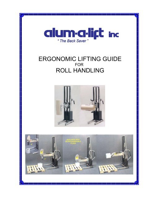
<strong>ERGONOMIC</strong> <strong>LIFTING</strong> <strong>GUIDE</strong><br />
FOR<br />
<strong>ROLL</strong> <strong>HANDLING</strong>
Since 1990, <strong>Alum</strong>-A-Lift has conceived, designed, developed and<br />
manufactured ergonomic lifting devices: Devices to lift, lower, move, position<br />
and hold objects too heavy for the unaided human.<br />
Responding to customer requests, primarily from major corporations, there<br />
have evolved groups of products that today comprise specialties, placed into<br />
niche market sectors. Sometimes what appears to be a unique application,<br />
thought never to be seen again, resurfaces; then, again and again. From the<br />
body of accumulated knowledge, elements can be modified, adapted and<br />
reused. Examples include lifts for use in class 100 cleanrooms, lifts for<br />
handling test fixtures, lifts for handling tool components used in the<br />
semiconductor industry and those used in the pharmaceutical and related<br />
industries.<br />
There are two parts to an <strong>Alum</strong>-A-Lift: The lift itself and the end effecter. The<br />
lift is selected from categories of constructions spanning a range of lifting<br />
capacities from 100 lbs to (now) 2000 lbs. Modular construction allows each<br />
construction to be modified as required to fit the specific application. End<br />
effecters allow the lift to perform its intended, sometimes unique, task. There<br />
is a very wide range of end effecters, emulating functions performed by the<br />
human body. Reach, grab, rotate and articulate are such typical functions.<br />
Common to all lifts is the strict adherence to all known applicable standards in<br />
the U.S. and in the EU Community, in which the CE Mark is a requirement. In<br />
contrast to other designs, our products are fail-safe.<br />
<strong>Alum</strong>-A-Lift is represented in almost all industrial nations and is thus able to<br />
provide local support in most situations. A policy is to have available spare<br />
parts, priced reasonably, that are shipped the same or next day upon receipt<br />
of order.<br />
Available is an Application Guide, showing step-by-step, the translation of<br />
basic information into a lift configured to solve the perceived lifting problem.<br />
Please feel free to request this informative booklet. Thank you.<br />
Stan Bressner
<strong>ROLL</strong> <strong>HANDLING</strong><br />
Roll handling is a daily task performed in essentially every industry. Two sets of opposing<br />
considerations are generally faced: Economics and ergonomics. The use of larger rolls<br />
results in fewer handlings, less scrap and lower downtime. Ergonomic guidelines, along<br />
with machine constraints, tend to limit the roll sizes that are actually used. The general<br />
objective is to optimize the handling system. The use of an ergonomic lifting device<br />
eliminates the risk of back injury thus allowing larger roll sizes and weights. It has been<br />
demonstrated that an investment in alum-a-lift will result in a relatively short pay-back<br />
period and thus represent a favorable return on assets employed.<br />
The handling strategy to be employed depends on the interaction of three sets of variables:<br />
The Roll: Dimensions, weight and constraints imposed by the material<br />
The Source: Location, conditions, constraints and roll orientation<br />
The Target: The take-up or pay-off device, location, height, roll orientation and constraints.<br />
Solutions to the handling problems are shown in groups of annotated images.<br />
TROUGHS<br />
When light to medium rolls are stored horizontally, are readily<br />
accessible, to have a through shaft inserted into the core and<br />
placed horizontally onto an accessible pay-off stand, a simple,<br />
static trough will serve as the end effecter. The trough may<br />
have a trapezoidal, triangular or curved shape to center rolls of<br />
varying diameters. The shaft is assembled to the core at the<br />
best ergonomic height. An extra shaft, inserted into the next<br />
roll to be used while on the lift, will serve to reduce the<br />
changeover and machine waiting time.
A trough may also<br />
be used to handle<br />
heavy rolls. Side<br />
guides and machine<br />
interlocks assure<br />
alignment and<br />
prevent the lift from<br />
moving when the<br />
roll is transferred<br />
from the lift to the<br />
pay-off stand.<br />
The machine pay-off may be a set of<br />
rollers onto which the roll is to be<br />
placed. At times, the location of the<br />
pay-off is at some distance from the<br />
accessible end of the using machine; or,<br />
there may be obstacles between the<br />
end of the machine and the pay-off<br />
rollers. An extended end effecter is<br />
used to span the distance to the rollers.<br />
A front stop, actuated by the user,<br />
releases the roll when the target is<br />
reached. As with all configurations,<br />
stability is a major consideration.<br />
Calculations are made to ascertain if<br />
and how much counter-mass is required<br />
to satisfy the stability criterion. After<br />
construction, the lift is subject to<br />
physical tests to assure stability.<br />
When the core is to be left open and the material is not<br />
fragile, the horizontal roll may be captured by a set of prongs or<br />
forks, with fixed or variable widths. This arrangement is used<br />
when the target is a cantilevered mandrel.
When the roll is horizontal at the source and a loose<br />
shaft is used to mount the roll onto a pay-off stand, a<br />
set of notched forks, spaced to straddle the roll, may<br />
be used. The shaft is first inserted into the roll’s core,<br />
and the shaft is used as the lifting point. If the roll is<br />
found on a pallet, the forks must be long enough to<br />
reach the core center from the edge of the pallet.<br />
Implied in this arrangement is clear access to the payoff<br />
stand on the using machine. If the rolls are to be<br />
found, supported by shafts, on a storage rack, the fork<br />
set is dimensioned to straddle the roll, while fitting<br />
between the roll ends and supporting brackets. With<br />
varying width rolls, the fork set may have adjustable<br />
widths.<br />
MANDRELS<br />
When the rolls are<br />
stored horizontally,<br />
and are to be placed<br />
onto an accessible,<br />
cantilevered mandrel,<br />
a boom is used to<br />
“spear” the roll, lift as<br />
required, and align<br />
with the machine<br />
mandrel. If the roll is<br />
fairly light, and easily<br />
transferred a smooth<br />
boom is used. If the<br />
roll is too heavy to be<br />
transferred manually,<br />
inset rollers ease the<br />
pushing task. Accessories include a spring loaded front stop that traps the roll on the lift’s<br />
mandrel until physical contact is made with the machine’s mandrel, and a docking<br />
arrangement with a male fitting attached to the machine’s mandrel and a female fitting<br />
attached to the lift’s mandrel. With the latter accessory, the roll is aligned slightly higher<br />
than the machine’s mandrel and then lowered until the two fittings are engaged. When the<br />
two fittings are engaged, there is effectively formed a continuous shaft abetting the<br />
transfer of the roll from the lift to the machine. Docking fittings are also available in sets<br />
and may be accordingly ordered.
When very heavy rolls are horizontal at the source and must be assembled to a<br />
machine mandrel, especially at higher elevations, a powered pusher is used.<br />
Along with a set of docking fittings, a continuous shaft is effectively formed for<br />
ease of transfer. With such heavy weights, the lift’s mandrel will deflect under<br />
load. Accordingly, docking fittings should be used to minimize misalignment<br />
between the mandrels. In some roll handling operations, such as laminating<br />
and printing, the roll is introduced at the pay-off end of the machine and the<br />
processed roll is to be removed from the take-up. In such instances, the pusher<br />
is used in reverse to become a puller. The roll is then transferred from the takeup<br />
back to the lift for subsequent handling.<br />
Various carts may be designed<br />
to temporarily store rolls. These<br />
carts are configured to interface<br />
with processing machinery and<br />
with alum-a-lift to form a<br />
handling system. The one<br />
shown here is equipped with a<br />
docking fitting to align its prongs<br />
with that on the lift. The prongs<br />
fold up, out of the way, for<br />
compact storage when the carts<br />
are not loaded. Carts have<br />
ergonomic handles, as do the<br />
alum-a-lift.
EXPANDING MANDRELS AND CLAMPING DEVICES<br />
More often than not, rolls are stored vertically (“eye-to-the-sky”) on pallets. Depending<br />
upon the rolls’ configuration, they may be stacked, one over the other in tiers. The pallets<br />
may be located in a warehouse or in an area in the vicinity of the processing machinery.<br />
The usual challenge is to capture a roll at some level on a pallet, lift it off, then rotate it<br />
90 o in order that the core become horizontal for assembly to a machine mandrel at some<br />
elevation. Often the pallets are located, for example, tightly spaced, sometimes along a<br />
wall or on the floor under a pallet rack. In such instances neither the alum-a-lift nor the<br />
human has access without having first moved the pallet to another location where access<br />
is provided to at least two sides or two corners of the pallet. Even with such access, the<br />
lift’s end effecter must have a reach length adequate to access all the rolls. Depending<br />
upon the rolls’ diameters, their array, and the pallet’s dimensions, the worst case is to<br />
reach the geometric center of the pallet. Attention must always be given to the loaded<br />
lift’s stability. In some situations, without room for forward projecting legs, a<br />
counterbalanced configuration may be required. This configuration inevitably leads to the<br />
addition of counterweights, adding to the load to be pushed and maneuvered. Applied<br />
creative thinking and willingness to improve handling conditions will often lead to a lighter,<br />
less costly lift and accompanying user-friendliness. One of two lifting strategies is<br />
employed: The expanding mandrel to capture the core; or a clamp to capture the roll by<br />
its outside.<br />
EXPANDING MANDREL, 3”, 6” OR BOTH, POWERED OR MANUAL<br />
When the inserted mandrel is expanded, a safe light comes on, signaling that it is safe to<br />
lift the roll. By utilizing a lead-in on the mandrel tip, the end effecter self aligns with the<br />
roll core during engagement. When proper depth of engagement is reached, the lifting<br />
function automatically shuts off, preventing damage to the equipment or the roll. Both<br />
the expanding and the articulating functions are powered on the unit illustrated. The<br />
operator does not have to leave his position to perform these functions. Also available<br />
at a lower cost is an end effecter that is manually operated. The roll weight and<br />
frequency of use determine the more economical method.
CLAMPS<br />
Clamps are used when the roll’s core must be left open and when the material will<br />
tolerate clamping action, especially on the outer layers. Clamp jaws are lined with a nonmarring,<br />
resilient (high friction) material. Powered and manual functions are available.<br />
Powered clamps have regulated clamping force. When vertically on pallets, rolls must be<br />
spaced to allow entry of the clamps jaws.<br />
Examples show manually operated clamps and manual rotation. Rolls should be clamped<br />
relatively close to their centers to minimize the tendency to pendulum. Clamps operated<br />
with hand wheels on both left and right hand sides.<br />
Manual clamp & manual rotation; with pivoting<br />
clamp jaws to rotate core from vertical to horizontal<br />
Powered clamp, manual<br />
rotation & pivoting clamp
ADVANCED CLAMPING DEVICES<br />
Powered clamp and powered rotation, with<br />
pivoting clamp jaws to re-orient core from<br />
vertical to horizontal. Heavy roll and overall<br />
weight of loaded lift make use of shuttling<br />
end effecter to align roll to the machine’s<br />
mandrel without having to relocate lift. With<br />
the heavily loaded lift, a powered drive is<br />
used, operated with a joystick.<br />
Powered clamp without rotation for<br />
capturing rolls with a wide range of<br />
diameters with the same end effecter.<br />
Clamp arms move left and right (equal &<br />
opposite) on linear rails. Without provision<br />
for forward projecting legs, a<br />
counterbalanced configuration is used.<br />
MOBILE <strong>ROLL</strong><br />
RACKS<br />
Designed to interface with<br />
alum-a-lift, these racks<br />
may be located close to<br />
the using machines.<br />
Often, conventional fork<br />
trucks are not welcome in<br />
such areas. Their use<br />
will save time awaiting<br />
fork trucks and their<br />
licensed drivers.
SOME SPECIAL CONDITIONS<br />
NARROW SPACING BETWEEN <strong>ROLL</strong>S<br />
Rolls with end inserts (spacers) are<br />
sometimes shipped horizontally on pallets,<br />
stacked one over the other. Rolls of photo<br />
resist material are shipped in this manner.<br />
The narrow, vertical space between rolls<br />
prevents the use of conventionally shaped<br />
clamp jaws. In such instances, one jaw is<br />
nearly flat so that it can enter the limited<br />
space, while the opposite jaw has a vee or<br />
trapezoidal shape to trap the roll.<br />
The powered clamp has a regulated<br />
clamping force to prevent damage to, or<br />
distortion of the roll.<br />
The same approach is used when vertically<br />
oriented rolls, on pallets, have limited space<br />
between tiers.<br />
SLIPPERY<br />
MATERIALS<br />
The tendency to<br />
telescope while lifting is<br />
prevented by introducing<br />
crescent shaped blades<br />
at the bottoms of the<br />
clamps. When on the<br />
machine mandrel, the<br />
blades move outward<br />
and leave the roll free to<br />
go all the way onto the<br />
machine mandrel.
EXAMPLE PROBLEMS & SOLUTIONS<br />
PROBLEM:<br />
LIMITED &<br />
DIFFICULT<br />
ACCESS.<br />
AWAIT FORK<br />
LIFT.<br />
SOLUTION:<br />
USE ALUM-A-<br />
LIFT. ANYONE<br />
CAN USE IT.<br />
PROBLEM:<br />
LONG <strong>ROLL</strong>S TO<br />
CUTTING TABLE.<br />
SOLUTION: LIFT<br />
WITH LONG<br />
BOOM ACTS AS<br />
PAY OFF SHAFT.<br />
PROBLEM: HOLD <strong>ROLL</strong> WHILE SHAFT<br />
IS INSERTED, THEN PLACE ONTO<br />
PAY-OFF STAND. SOLUTION, SHORT<br />
VEE TROUGH.
7909 Bankhead Hwy<br />
Winston, GA 30187<br />
Tel 770 489 0328<br />
Fax 770 489 7247<br />
www.alum-a-lift.com<br />
stanb@alum-a-lift.com
PLACE THE PALLET ON THE DOLLY<br />
INSTEAD OF ON THE FLOOR.<br />
DOING SO WILL:<br />
PROVIDE CRAWL SPACE FOR LIFT’S<br />
FORWARD PROJECTING LEGS<br />
REDUCE REACH DISTANCE FOR END<br />
EFFECTER<br />
ELIMINATE OR MINIMIZE COUNTER<br />
WEIGHTS<br />
ALLOW FOR A LIGHTER, MORE<br />
USER FRIENDLY LIFT<br />
LOCATE PALLET WHERE MOST<br />
CONVENIENT<br />
SAVE FLOOR SPACE<br />
ELIMINATE WAITING TIME FOR FORK<br />
LIFT & LICENSED DRIVER
<strong>ROLL</strong> CART<br />
SOME ADDITIONAL EXAMPLES FROM<br />
“THE BACKSAVER”