Specification Sheet - VTC Pro Audio
Specification Sheet - VTC Pro Audio
Specification Sheet - VTC Pro Audio
- No tags were found...

You also want an ePaper? Increase the reach of your titles
YUMPU automatically turns print PDFs into web optimized ePapers that Google loves.
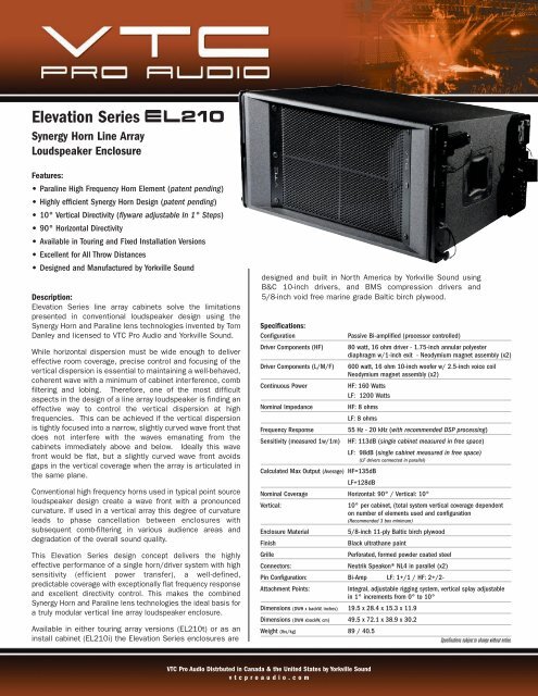
Elevation SeriesSynergy Horn Line ArrayLoudspeaker EnclosureFeatures:• Paraline High Frequency Horn Element (patent pending)• Highly efficient Synergy Horn Design (patent pending)• 10° Vertical Directivity (flyware adjustable In 1° Steps)• 90° Horizontal Directivity• Available in Touring and Fixed Installation Versions• Excellent for All Throw Distances• Designed and Manufactured by Yorkville SoundDescription:Elevation Series line array cabinets solve the limitationspresented in conventional loudspeaker design using theSynergy Horn and Paraline lens technologies invented by TomDanley and licensed to <strong>VTC</strong> <strong>Pro</strong> <strong>Audio</strong> and Yorkville Sound.While horizontal dispersion must be wide enough to delivereffective room coverage, precise control and focusing of thevertical dispersion is essential to maintaining a well-behaved,coherent wave with a minimum of cabinet interference, combfiltering and lobing. Therefore, one of the most difficultaspects in the design of a line array loudspeaker is finding aneffective way to control the vertical dispersion at highfrequencies. This can be achieved if the vertical dispersionis tightly focused into a narrow, slightly curved wave front thatdoes not interfere with the waves emanating from thecabinets immediately above and below. Ideally this wavefront would be flat, but a slightly curved wave front avoidsgaps in the vertical coverage when the array is articulated inthe same plane.Conventional high frequency horns used in typical point sourceloudspeaker design create a wave front with a pronouncedcurvature. If used in a vertical array this degree of curvatureleads to phase cancellation between enclosures withsubsequent comb-filtering in various audience areas anddegradation of the overall sound quality.This Elevation Series design concept delivers the highlyeffective performance of a single horn/driver system with highsensitivity (efficient power transfer), a well-defined,predictable coverage with exceptionally flat frequency responseand excellent directivity control. This makes the combinedSynergy Horn and Paraline lens technologies the ideal basis fora truly modular vertical line array loudspeaker enclosure.Available in either touring array versions (EL210t) or as aninstall cabinet (EL210i) the Elevation Series enclosures aredesigned and built in North America by Yorkville Sound usingB&C 10-inch drivers, and BMS compression drivers and5/8-inch void free marine grade Baltic birch plywood.<strong>Specification</strong>s:ConfigurationDriver Components (HF)Driver Components (L/M/F)Continuous PowerPassive Bi-amplified (processor controlled)80 watt, 16 ohm driver - 1.75-inch annular polyesterdiaphragm w/1-inch exit - Neodymium magnet assembly (x2)600 watt, 16 ohm 10-inch woofer w/ 2.5-inch voice coilNeodymium magnet assembly (x2)HF: 160 WattsLF: 1200 WattsNominal Impedance HF: 8 ohmsLF: 8 ohmsFrequency Response 55 Hz - 20 kHz (with recommended DSP processing)Sensitivity (measured 1w/1m) HF: 113dB (single cabinet measured in free space)LF: 98dB (single cabinet measured in free space)(LF drivers connected in parallel)Calculated Max Output (Average) HF=135dBLF=128dBNominal Coverage Horizontal: 90° / Vertical: 10°Vertical:10° per cabinet, (total system vertical coverage dependenton number of elements used and configuration(Recommended 3 box minimum)Enclosure Material5/8-inch 11-ply Baltic birch plywoodFinishBlack ultrathane paintGrillePerforated, formed powder coated steelConnectors:Neutrik Speakon® NL4 in parallel (x2)Pin Configuration: Bi-Amp LF: 1+/1 / HF: 2+/2-Attachment Points:Integral, adjustable rigging system, vertical splay adjustablein 1° increments from 0° to 10°Dimensions (DWH x backW, inches) 19.5 x 28.4 x 15.3 x 11.9Dimensions (DWH xbackW, cm) 49.5 x 72.1 x 38.9 x 30.2Weight (lbs/kg) 89 / 40.5<strong>Specification</strong>s subject to change without notice.<strong>VTC</strong> <strong>Pro</strong> <strong>Audio</strong> Distrbuted in Canada & the United States by Yorkville Soundvtcproaudio.com
Elevation Series EL210Technology OverviewParaline ElementThe Paraline element is a horn configuration that provides an effectiveimpedance transformation while at the same time providing a way toadjust the path length in a continuously variable way, such that the highfrequency dispersion pattern produced has the same characteristicsas that of a much deeper conventional horn.In order to have dispersion from two separate sources combinewithout interference, it is necessary to have each source produce avery specific radiation pattern. This is particularity true in a line arraywhere the vertical dispersion angle of the high frequencies must beMUCH narrower and where a conventional horn design would bephysically far too deep to be practical.Synergy HornThe Synergy Horn successfully couples the radiation from multipledrivers into a single horn configuration.In the EL210, two 10-inch low /mid frequency drivers are mounted tothe Synergy Horn along with two compression drivers mounted on aParaline horn element. This coaxial horn arrangement uses the entirefront area of the enclosure as the horn mouth for both mid and highfrequencies. This maximizes the horn size, improving directionalcontrol at lower frequencies (longer wavelengths) while maintainingreasonable overall enclosure size.The Paraline element eliminates the impractical depth needed to makean array of conventional horns that would sum into a non-interferingsource. In the case of the EL210, a vertical dispersion pattern of 10°is achieved with a Paraline element less than one inch deep, where aconventional horn would be several metres in length.To control and maintain a well-defined horizontal dispersion pattern,the Paraline element is mounted on a conical horn.<strong>VTC</strong> <strong>Pro</strong> <strong>Audio</strong> Distrbuted in Canada & the United States by Yorkville Soundvtcproaudio.com
Elevation Series EL210Flying Details - Touring Version (EL210t)Rigging, Flyware & BumpersThe custom designed Elevation Series’ rigging hardware provides a rugged,extremely secure suspension system for large-scale flown arrays. Individualcabinets are attached together and angled using quick-attach pins, includedwith the frame.Two optional Elevation Series flying bumpers are available for Elevation Seriesline array cabinets. The ELB16 bumper can handle up to 18 EL210t boxes ina flown in a vertical array, and is the ideal large format bumper for full scaletouring systems and J-Arrays from trussing or roof rigging. Elevation SeriesELS212t subwoofers can be flown in the same vertical array with the EL210tfull range enclosures for convenient fully flown touring systems with the ELB16.The ELB8 bumper can handle up to 12 EL210t boxes in a flown straightvertical array, or any combination of ELS212t subwoofers and EL210tcabinets not exceeding 1500lbs (681kg). Compact and more cost effectivethan the full sized ELB16, the ELB8 is the ideal platform for flying ElevationSeries cabinets from portable or telescoping tower lifts where full scale trussrigging is not available.Either the ELB8 or ELB16 can be used as a secure level platform for verticalground stacking of Elevation Series cabinets in venues where a flown array isnot the most cost effective practical system solution.Flying Details – Installation Version (EL210i)<strong>VTC</strong> Elevation Series install hardware integrated into the EL210i is the mostcost-effective, safe and secure system available for building compact arrays forfixed permanent installation. Custom designed and manufactured using 10guage (.135-inch) steel , EL210i Installation hardware allows a maximum of 4EL210i cabinets to be quickly and easily configured and arrayed in splays from0 to 10° per cabinet in 1° increments using 3/8th-inch hex bolts (included).Integrated pickup points in the EL210i hardware allow the array to be easilyflown using a two or four point hang.Additional Information on Flying SystemsUse only <strong>VTC</strong> flyware and bumper for any large-scale flown arrays and do notexceed the maximum cabinet configurations listed. Correctly knowing how touse all of the suspension hardware and components is imperative in soundsystem rigging and deployment.Research local codes and regulations to fully understand therequirements for suspended loads in the venue in which theequipment is to be suspended. Always calculate suspendedloads before lifting array to ensure suspension componentsand hardware being used are well within their respectiveload limits.Consult a professional mechanical or structural engineerlicensed in the jurisdiction where the sound system will beused to review, verify and approve all attachments to thebuilding or structure.Never assume owner or third-party supplied suspension orattachment points are adequate for the loads to be suspended.Be absolutely certain of the integrity of any structuralmember intended to support suspended loads. Hiddenstructural members can have hidden structural weakness,modifications or other defects.Always employ the services of a professional rigger for hoisting,positioning, and attaching the equipment to any supportingstructure, building or mobile trussing.Refer to local building codes and regulations regarding flownhardware or fixtures and strictly adhere to them.EL16B bumper should only be attached to a flying rig withCrosby 5/8th-inch shackles or approved equivalent (Crosby1/2-inch shackle or equivalent on the ELB8). In either case,use only shackle holes in bumper for suspension of array.Always inspect all components (enclosures, suspensionbrackets, pins, frames, bolts, nuts, slings, shackles, etc.) forcracks, wear, deformation, corrosion, missing, loose, ordamaged parts that could reduce the strength of theassembly before lifting. Discard any worn, defective, orsuspect part and replace them with the appropriateload-rated replacement partPlease Note: Elevation Series Cabinets can ONLY be fixedto ELB16 with custom Jergens stainless steel pins (Yorkvillepart #8980) included with the bumper. Cabinets used onELB8 must be attached with custom Jergens stainless steelpins (Yorkville part #8971) included with the ELB8. Jergenspins connecting cabinets to bumpers in either case must besecured with supplied cotter pins.<strong>VTC</strong> <strong>Pro</strong> <strong>Audio</strong> Distrbuted in Canada & the United States by Yorkville Soundvtcproaudio.com
Suggested Flying Configurations with ELB16 Bumper:Maximum Cabinets:18 x EL210t straight vertical hang14 x EL210t J-Array (top 7 cabinets Vertical (straight)and remaining 7 fully splayed at 10° each)8 x EL210t Cabinets only if fully splayed at 10° eachGround Stack Configurations with ELB16 BumperMaximum Cabinets:8 x EL210t splayed maximum 5° each2 x ELS212t Subwoofers / 6 x EL210t splayed maximum 5° eachSuggested Flying Configurations with ELB8 Bumper:Maximum Cabinets:12 x EL210t7 x ELS212tAny combination of EL210T and ELS212T cabinets not exceedinga maximum combined weight of 1500lbs.Ground Stack Configurations with ELB8 BumperMaximum Cabinets:4 x EL210t splayed maximum 10° eachTour Hardware Quick PinGround Stack Configurations with No BumperMaximum Cabinets:2 x ELS212t Subwoofers and4 x EL210t splayed maximum 10° eachDo not ground stack EL210t cabinets without ELB8, ELB16or ELS212t subwoofers as foundation.EL210i Installation hardware<strong>VTC</strong> <strong>Pro</strong> <strong>Audio</strong> Distrbuted in Canada & the United States by Yorkville Soundvtcproaudio.com
H.F Response Unprocessed1w (2.8V) 1m Free SpaceH.F ImpedanceMagnitudeH.F Horizontal ResponseUnprocessed Free SpaceBlue=0°, Red=15°, Purple=30°, Green=45°H.F Vertical ResponseUnprocessed Free SpaceBlack=0°, Red=5°, Purple=10°<strong>VTC</strong> <strong>Pro</strong> <strong>Audio</strong> Distrbuted in Canada & the United States by Yorkville Soundvtcproaudio.com
L.F Response Unprocessed1w (2.8V) 1m Free Space (Black) & Ground Plane (Red)L.F ImpedanceMagnitude<strong>Pro</strong>cessed Frequency Response1 Cabinet Free SpaceDLMS4080 ResponseRed Curve "EL210 Low, Two-way with Sub"Blue Curve "EL210 Low, Two-way full range"<strong>VTC</strong> Elevation 05/02/08 10:44:05Bu10 20 50 100 200 500 1k 2k 5k 10k 20k 30kHz<strong>VTC</strong> <strong>Pro</strong> <strong>Audio</strong> Distrbuted in Canada & the United States by Yorkville Soundvtcproaudio.com
28.39”28.3919.52”28.39”28.3919.52”19.5215.29”11.8912.05”<strong>VTC</strong> <strong>Pro</strong> <strong>Audio</strong> Distrbuted in Canada & the United States by Yorkville Soundvtcproaudio.com