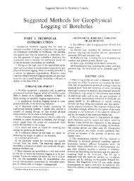
28 <strong>ISRM</strong> (India) JournalInitially, 50 m x 60 m pillars were divided into three halvesby driving 4.8 m x 3 m level split galleries. <strong>The</strong> size <strong>of</strong>stooks after splitting was 15.2 m x 50 m. <strong>The</strong> splitting<strong>of</strong> pillars was restricted to 2 pillars ahead <strong>of</strong> <strong>the</strong> line <strong>of</strong>extraction. A diagonal line <strong>of</strong> face was maintained atabout 60 0 .3.1 Safety Factor <strong>of</strong> <strong>the</strong> PillarsUnder normal pillar extraction condition, <strong>the</strong> localmine stiffness remains more or less constant while <strong>the</strong>reduction in pillar strength with <strong>the</strong> reduction in pillar sizegenerates a situation conducive to violent failure. Here,increasing <strong>the</strong> extraction ratio by splitting/stoking <strong>of</strong> pillarsahead <strong>of</strong> <strong>the</strong> face may be dangerous to <strong>the</strong> working area.Laboratory scale specimens become elasto-plastic whenwidth/height ratios approach 8 (Das 1986). In accordancewith <strong>the</strong> field data available for <strong>the</strong> actual failure <strong>of</strong> apillars (Sheorey 1993), <strong>the</strong> post failure modulus <strong>of</strong> a pillarwith width/height ratio about 4 becomes positive and itsbehaviour changes from strain-s<strong>of</strong>tening to elasto-plastic.Fortunately, <strong>the</strong> BG does not involve <strong>the</strong> process <strong>of</strong>splitting/stoking ahead <strong>of</strong> <strong>the</strong> face, except for splitting andslicing <strong>the</strong> pillars being extracted. Under <strong>the</strong>se conditions,<strong>the</strong> chance <strong>of</strong> <strong>the</strong> violent failure <strong>of</strong> a pillar becomes lowand is limited to <strong>the</strong> pillar being extracted. <strong>The</strong> safetyfactor <strong>of</strong> <strong>the</strong> pillars <strong>of</strong> panel-3B remains nearly 2.33 fornormal height (3 m) pillar extraction, while <strong>the</strong> same forfull-height working <strong>of</strong> <strong>the</strong> seam by <strong>the</strong> BG method (11 m)with double splitting goes below one.Table 1: Pillar size variation as per regulation 99 <strong>of</strong>Indian Coal Mining Regulations, 1957 (CMR 1957).3.2 Strata MonitoringField instrumentation was carried out in panel-3B tostudy stress distribution in <strong>the</strong> panel, load on hydraulicprops in galleries, convergence in galleries, ro<strong>of</strong> layersmovement and stress change in <strong>the</strong> panel. Details <strong>of</strong> fieldinstrumentation programme are given here (Fig. 7):• Stress measurements in BG workings. Five vibratingwire stress cells, S 1at 66BLN/39D, S 2at 67LS/39D, S 3at 67ALS/39D, S 4at 68ALS/39D and S 5at 68BLS/39D,were installed in <strong>the</strong> BG panel.• Load over O.C. props in galleries. Vibrating wire loadcells were installed on <strong>the</strong> O.C. hydraulic props, till10 m ahead <strong>of</strong> working face in galleries. Recordingsfrom load cells were obtained at every 10 m interval.Load cells were shifted to new stations after every 10m <strong>of</strong> face retreat in <strong>the</strong> galleries.• Convergence in gate roads. Ro<strong>of</strong> to floor convergencewas monitored at every 10 m interval in galleries usingtelescopic convergence indicators.• Immediate ro<strong>of</strong> layers movement. Three Tell-taleextensometers, T1 at 66L, T2 at 67L and T3 at 68L,were installed in <strong>the</strong> junctions <strong>of</strong> <strong>the</strong> BG panel.Depth cover(m)Pillar size (center to center) for differentgallery widths (m)3.0 m 3.6 m 4.2 m 4.8 m360 39.0 42.0 45.0 48.0Pillars formed (Table 1) in accordance with <strong>the</strong> CoalMining Regulations possess adequate safety factorsand a high w/h ratio which sustain <strong>the</strong> various miningconditions resulting from pillar extraction at normalheights. However, <strong>the</strong>re is an indirect increase in <strong>the</strong>height <strong>of</strong> pillars due to <strong>the</strong> winning <strong>of</strong> <strong>the</strong> ro<strong>of</strong> coal by <strong>the</strong>BG method (Singh et al., 2007). <strong>The</strong> process <strong>of</strong> ro<strong>of</strong> coalwinning affects <strong>the</strong> stability <strong>of</strong> pillars designed for normalheight workings developed in accordance with <strong>the</strong> CoalMining Regulations.Fig. 7 : Location <strong>of</strong> different monitoring instruments.4. Results and discussion4.1 Stress Variation Over <strong>the</strong> Pillars<strong>The</strong> measurements obtained from vibrating wire stresscells at 66BLN/39D (S 1), 67LS/39D (S 2), 67ALS/39D(S 3), 68ALS/39D (S 4) and 68BLS/39D (S 5) are presentedVolume 2 No. 1 <strong>January</strong> <strong>2013</strong>
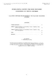
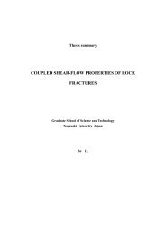
Strata Monitoring Studies in Blasting Gallery Panel During Depillaring Based on Field Instrumentationwith respective to area <strong>of</strong> extraction <strong>of</strong> Panel-3B is presented in Fig. 10. <strong>The</strong>re29was anincrease in load <strong>of</strong> 22 t over O.C. props for <strong>the</strong> initial area <strong>of</strong> extraction <strong>of</strong> about 4000 min Fig. 8 and 9. Variation <strong>of</strong> stress was found in all cells and observed on O.C. props indicated <strong>the</strong> occurrence <strong>of</strong> ro<strong>of</strong>2its magnitude increased as <strong>the</strong> area <strong>of</strong> extraction increases and 32 fall t for in fur<strong>the</strong>r <strong>the</strong> area goaf, <strong>of</strong> extraction due to <strong>of</strong> induced about 5300 blasting m 2 <strong>the</strong> panel. practices. Afterand <strong>the</strong> face retreated closer to <strong>the</strong> station. It can be seen Subsequently, that, increase noticeable in load decrease was in load observed <strong>of</strong> 25 t over with O.C. respective props was observed to forthat <strong>the</strong> stress cell (S 1) recorded higher stress compared fur<strong>the</strong>r area <strong>of</strong> <strong>of</strong> extraction about <strong>of</strong> 6200 27 mt 2 for . Thus, 7000 <strong>the</strong> sudden m 2 , 28 decrease t for 8000 in load mobserved 2 , onto o<strong>the</strong>r stress cells installed in <strong>the</strong> panel-3B. <strong>The</strong> reasons O.C. props32 tindicatedfor 8600<strong>the</strong>m 2 occurrenceand 39 t<strong>of</strong>forro<strong>of</strong>10060fall inm<strong>the</strong> 2 . <strong>The</strong>segoaf, duerecordingsto induced blastingcould be <strong>the</strong> large overhangs in goaf towards 66AL North, showed regular increase in load, indicating periodic buildup<strong>of</strong> load on galleries, and increase in load may be duepractices. After that, increase in load was observed with respective to area <strong>of</strong> extraction <strong>of</strong>66BL North and 67L North and nearer to <strong>the</strong> goaf edge27 t fordistance compare to <strong>the</strong> o<strong>the</strong>r stress cells in <strong>the</strong> panel. to 7000 non-caving m 2 , 28 t for <strong>of</strong> 8000 goaf. mO.C.2 , 32 t for 8600 m 2 and 39 t for 10060 m 2 . <strong>The</strong>serecordings showed regular increase in load, indicating periodic build-up <strong>of</strong> load on galleries,Fur<strong>the</strong>r O.C props experienced higher loads in 66AL5and increase North, in load 66BL may be North, due to non-caving 67L and <strong>of</strong> goaf. 67AL O.C. South, and load66BLN/39Dvaries Fur<strong>the</strong>r from O.C 30 props t - 39 experienced t. <strong>The</strong> panel higher loads experienced in 66AL North, supports 66BL North, 67L67LS/39D4and 67AL displacements South, and load in varies galleries from 30 <strong>of</strong> t 66AL - 39 t. North, <strong>The</strong> panel 66BL experienced North, supports67ALS/39Ddisplacements 67L and in galleries 67AL <strong>of</strong> South. 66AL North, 66BL North, 67L and 67AL South.Increase in stress (MPa)Increase in stress (MPa)32103500 5500 7500 9500 115005excavation area (m 2 )66BLN/39D68ALS/39D68BLS/39DFig. 8 : Stress recordings with respective to area <strong>of</strong>exxtraction in Panel-3B.4.2 Load Variation in <strong>the</strong> Galleries<strong>The</strong> load over O.C. props was recorded during panelextraction. Initial load in all <strong>the</strong> load cells was maintained 5 t.<strong>The</strong> change in load was calculated based on final load recordedbefore <strong>the</strong> removal <strong>of</strong> O.C. prop as face approached it.<strong>The</strong> change in load <strong>of</strong> O.C. props with respective to area <strong>of</strong>extraction <strong>of</strong> Panel-3B is presented in Fig. 10. <strong>The</strong>re was anincrease in load <strong>of</strong> 22 t over O.C. props for <strong>the</strong> initial area<strong>of</strong> extraction <strong>of</strong> about 4000 m 2 and 32 t for fur<strong>the</strong>r area <strong>of</strong>extraction <strong>of</strong> about 5300 m 2 in <strong>the</strong> panel.Subsequently, noticeable decrease in load <strong>of</strong> 25 t overO.C. props was observed for fur<strong>the</strong>r area <strong>of</strong> extractionabout 6200 m 2 . Thus, <strong>the</strong> sudden decrease in loadMax. change in load (t)4030201000 2000 4000 6000 8000 10000 12000area <strong>of</strong> extraction (m 2 )Fig.467LS/39DFig.10 :10Loadloadrecordingsrecordings iningalleriesgalleriesininPanel-3B.Panel-3B.67ALS/39D4.3 Convergence in Galleries368ALS/39D4.3 Convergence in galleriesRo<strong>of</strong> to floor convergence was monitored at 10 m intervals68BLS/39DRo<strong>of</strong> to (i.e. floor station convergence C1, was C2, monitored C3, C4, at 10 C5, m intervals C6, (i.e. C7, station C8, C1, C9 C2, and C3, C4, C5,2C10) from goaf edge in each level <strong>of</strong> Panel-3B duringC6, C7, C8, C9 and C10) from goaf edge in each level <strong>of</strong> Panel-3B during depillaring.depillaring.1<strong>The</strong> convergence in galleries with respective to area <strong>of</strong> extraction analysed during<strong>The</strong> convergence in galleries with respective to area <strong>of</strong>depillaring in Panel-3B are shown in Fig. 11. Convergence is increasing with area <strong>of</strong>extraction analysed during depillaring in Panel-3B are0extraction increased. Results revealed that all <strong>the</strong> stations that recorded cumulative100 80 60 40 200shown in Fig. 11. Convergence is increasing with area <strong>of</strong>extraction increased. Results revealed that all <strong>the</strong> stationsGoaf edge distance (m)that recorded cumulative convergence higher than 100mm were experiencing large overhangs in goaf evenFig. 9 : Stress recordings with respective to goaf edgethough induced blasting practices in goaf.distance in Panel-3B.Page 11 <strong>of</strong> 15Convergence (mm)200160120804000 2000 4000 6000 8000 10000 12000excavated area (m 2 )Fig. 11 : Convergence recordings in galleries withrespective area <strong>of</strong> extraction in panel – 3B.Volume 2 No. 1 <strong>January</strong> <strong>2013</strong>