ISSN - ISRM
ISSN - ISRM
ISSN - ISRM

You also want an ePaper? Increase the reach of your titles
YUMPU automatically turns print PDFs into web optimized ePapers that Google loves.
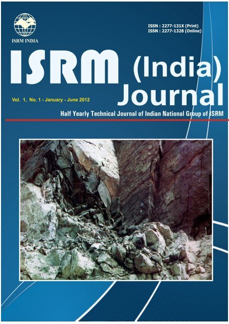
<strong>ISSN</strong> : 2277-131X (Print)<strong>ISSN</strong> : 2277-1328 (Online)<strong>ISRM</strong> (India)JournalVol. 1, No. 1 - January - June 2012Half Yearly Technical Journal of Indian National Group of <strong>ISRM</strong>
AIMS AND SCOPE<strong>ISRM</strong> (India) Journal is a half yearly journal of the Indian National Group of International Society forRock Mechanics (<strong>ISRM</strong>), which is involved in dissemination of information on rock mechanics, and itsrelated activities in the field of foundation and abutments of dams, tunnel engineering, mining, undergroundworks, rock slope stability, road works, etc.The aim of the journal is to encourage exchange of ideas and information between rock mechanicspractitioners worldwide. The journal provides an information service to all concerned with Rock Mechanicsabout the development of techniques, new trends, experience gained by others to enable updating ofknowledge. The original manuscripts that enhance the level of research and contribute new developmentsto the Rock Mechanics are encouraged. The journal is expected to exchange ideas and informationbetween Rock Mechanics practitioners, help researchers, technologist and policy makers in the keysector of Water Resources, Infrastructure Development (including underground works), Hydro Power,Mining and Petroleum Engineering, etc. to enhance their understanding of it. The Journal has both printand online versions. Being peer-reviewed, the journal publishes original research reports, review papersand communications screened by the Editorial Board, consisting of renowned experts.The manuscripts must be unpublished and should not have been submitted for publication elsewhere.There are no Publication Charges.EDITORIAL BOARD• Dr. David Beck, Beck Engineering, AUSTRALIA• Dr. A.K. Dhawan, Chief Consultant, Fugro Geotech Ltd. and Former Director, Central Soil andMaterials Research Station, INDIA• Prof. Xia-Ting Feng, Institute of Rock and Soil Mechanics, The Chinese Academy of Sciences,CHINA• Dr. Abdolhadi Ghazvinian, Department of Mining Engineering, Faculty of Engineering, Tarbiat-Modares University, IRAN• Dr. R.K. Goel, Chief Scientist, Central Institute of Mining and Fuel Research, Regional Centre,Roorkee, INDIA• Dr. Luis Lamas, Secretary General, <strong>ISRM</strong> and Head of the Foundations and Underground WorksDivision, Portuguese National Laboratory of Civil Engineering, PORTUGAL• Dr. A. Nanda, Deputy General Manager, Engineers India Limited, Sub Surface Projects Division,INDIA• Dr. H.R. Sharma, Director – Design and Engineering, GVK Technical & Consultancy Services Pvt.Ltd., INDIA• Dr. K.G. Sharma, Professor, Department of Civil Engineering, Indian Institute of Technology Delhi,INDIA• Dr. Antonio Samaniego, Principal Lecturer (Rock Mechanics), Catholic University of Peru, PERU• Dr. Yingxin Zhou, Defence Science & Technology Agency, SINGAPORE
INDIAN NATIONAL GROUP OF <strong>ISRM</strong><strong>ISRM</strong> (INDIA) JOURNALVolume 1, No. 1 January 2012CONTENTSPage No.MESSAGE FROM PRESIDENT 3FROM EDITOR’S DESK 4• Dynamic Properties of Sandstone Rock Subjected to Cyclic Loading - M.N. Bagde and V. Petros 5• Tunnels in Weak Ground : Discrete Element Simulations – S.D. Anitha Kumari and T.G. Sitharam 17• Determination of Stress Orientation and Magnitude in a Directional Well bore, Case Study :Mansouri-54 Wellbore of Southwest Iranian Oilfield – O. Saeidi and M. Ahmadi 25Governing Council Indian National Group for the Term 2011-2014 31Brief Profile of the Office Bearers of Indian National Group of <strong>ISRM</strong> 32Recent Activities of Indian National Group• Seminar on “Grouting and Deep Mixing” - 25-26 August 2011, New Delhi 33• Seminar on “Slope Stabilization Challenges in Infrastructure Projects” - 20-21 October 2011,New Delhi 34<strong>ISRM</strong> News 36Publications – Manual on Rock Mechanics 38<strong>ISRM</strong> Sponsored Forthcoming Events 38Guidelines for Authors 39All communications to be addressed to :The Member SecretaryIndian National Group of <strong>ISRM</strong>CBIP Building, Malcha MargChanakyapuri, New Delhi – 110 021Volume 1 v No. 1 v January 2012
MESSAGEI feel greatly honoured to be elected as President of the InternationalSociety for Rock Mechanics (India) – <strong>ISRM</strong> (India) for the term till 2014.I thank all the Members of the Society for unanimously electing me as thePresident.I thank my predecessor, Dr. K.G. Sharma, who guided the Society for almost6 years, and was pioneer in bringing the Indian Chapter as one of the mostactive Chapter of the <strong>ISRM</strong>.One of my first priorities, as President, is to increase its Membership, which Iconsider is necessary for overall growth of the Society.On the Membership front, we stand 4th amongst all National Groups but there is need to furtherincrease the Membership by bringing all concerned in its fold, and this would be possible only with thesupport of all concerned.There is no reason why India cannot be amongst the best of the National Groups of the Society. I feelwe need to bolster the Technical Activities of the Society such as Conferences; Workshops and TrainingProgrammes ensuring high standards, besides providing all the necessary information to the participants.This would be possible by the cooperation and active support of all the Members.I also take this opportunity to share with you that Dr. Manoj Verman has been elected as 3rd <strong>ISRM</strong> VicePresident at Large for the term 2011-14. Dr. German has also been designated as President of <strong>ISRM</strong>Commission on “Hard Rock Excavation”. This is a moment of great pride for the Rock MechanicsCommunity of India.The Inaugural Issue of <strong>ISRM</strong> (India) Journal is a step towards exchange of ideas and informationbetween Rock Mechanics practitioners worldwide. I request all the readers to offer their valuablecomments to enable us to improve its quality and utility.I wish you all a Very Happy and Prosperous New Year – 2012. May the New Year bring you ExcellentHealth, Happiness and Best Success in your profession.President, <strong>ISRM</strong> (India)&Director (Design & Engg.), GVK Group
6 <strong>ISRM</strong> (India) Journalamong the mining coalfields where, due to the givennatural conditions, rock burst occurs. Hard coal seamshave been mined in this area by underground miningmethods for more than 200 years. The first rock burstwas recorded in 1912.Geological structure is quite variable. The depositcomprises of typical multi-seams and vertical distancebetween seams varies from a few meters up to severaltens of meters. Rock burst started to be more and morefrequent during the nineteen-seventies in part of theKarvina coalfield. The Karvina part is featured by a meanworked thickness of about 2.5 m (contrary to the presentwind-up Ostrava section of the coalfield where it is about1.1 m). The rock massif in the Karvina section, especiallyin saddle strata, consists mostly of solid siltstones,sandstones and conglomerates with uniaxial compressivestrength of sandstone between 70 and 90 MPa.Compressive strength of coal is usually between 20 and25 MPa, rarely even 35 MPa. Mining depth presently isabout 800 m below the surface. During the last decadeof the 20th century, drastic reduction in coal productionoccurred in OKC. Reduction of the annual coal productionfrom about 24 million tonnes to about 14 million tonnesis manifested by the abandoning of mines in the Ostravapart. Within 25 years, i.e., between 1977 and 2002, noevidence is found of dependence between the volume ofcoal output (both total output and output of rock burstprone seams) and the frequency of rock burst. Thus, rockburst is obviously connected with geological andgeomechanical conditions under which mining activity iscarried out, and equally, with the intensity and successof continuously performed rock burst control measures.According to Konecny et al., (2003) rock burst in OKC isexclusively in-seam rock burst, directly linked with mineworkings advanced in the same coal seam. A criticalstress field is developed in the vicinity of the mineworkings. A brittle failure of coal seam occurs at this eventand the failure of roof strata and floor strata is minimal.When coal mining has passed into greater stratigraphicdepths where above the coal seam N 530 0 , a more than100-160 m thick zone of rigid rocks without anycontinuously developed workable seams existed, the rockburst with its focus area outside the coal seam started tobe manifested. The occurrence of critical stress field insuch cases leads to brittle failure, not only of coal, butalso with part of the rock massif. Such rock bursts arethen, as a rule, a result of long-term and combined formingof unfavourable stress conditions in the given geologicalstructure. Thus, rock bursts in OKC are considered ascomplex geomechanical events, in which the relationshipbetween natural and technological factors and resultantmanifestations is very complicated.According to Petroš and Holub, (2003), the strongest rockburst that occurred during the last ten years in the OKChad P- and S- wave frequencies of about 5 Hz. Resultsof their detailed analysis and study (for more detail, seePetroš and Holub, 2003, Petroš et. al., 2004) arepresented in Fig. 1 as a dependence of released seismicenergy of rock burst versus prevailing frequency of P-and S-wave maximums. It is reported that frequencies ofground velocities of P- and S- waves are observedgenerally within the intervals of about 3-22 Hz and 2-16Hz, respectively. However, according to them mostoccurred prevailing frequencies of P- and S- waves areobserved mostly within the range of about 3-12 Hz and2-9 Hz, respectively.(a) P-waves(b) S-wavesFig. 1 : Dependence of released seismic energy of rock burst vs. prevailing frequency of P- and S-wavesfor hypo-centric distance of 500-6000 m (after Petroš et al., 2004)Volume 1 v No. 1 v January 2012
Dynamic Properties of Sandstone Rock Subjected to Cyclic Loading73.0 TESTED ROCKThe rock tested was mostly carboniferous sandstoneobtained from the rock burst prone Darkov coal mine.The rock cores represent borehole Darkov 265-01. Thesamples were obtained from borehole cores in the saddlelayer sandstone, at an approximate depth ranging from930 to 980 m below surface in the case of Darkov.Samples were obtained from Darkov mine and sampleNo. 95-113 is referred to as Darkov 265-01-1 (thenreferred to as D1), from sample No. 114-118 as Darkov265-01-2 (D2) etc., and hereafter, they are referred to asD1, D2, D3, D4, D5, D6, D7, D8 and D9, respectively.Details about various nomenclatures used to identifyrock samples and their respective depth is provided inTable 1. The term “sample” refers to the block or cores ofrock obtained from a site, while the term “rock specimen”refers to the specific piece of rock prepared and tested.Fig. 2 shows the prepared rock specimens from differentsamples obtained from borehole Darkov 265-01.The tested rock specimens were of L/D ratio of 1 with anaverage diameter of 47.7 mm. Rock samples obtainedfrom vertical borehole in the form of cores and rockspecimens were prepared from the obtained cores andthus, loading direction in uniaxial compression testing inthe laboratory was parallel to borehole axis. Rockspecimens were prepared and tested according to <strong>ISRM</strong>testing procedure and guidelines (Fairhurst and Hudson,1999).Table 1 : Nomenclature used to identify rock samples with their respective depth andnumbers of tested rock specimensSample Identification Symbol Depth below surface (m) SpecimensBorehole: Darkov 265-01, Mine: Darkov95-113 Darkov 265-01-1 D1 929-947 2114-118 Darkov 265-01-2 D2 948-952 2119-122 Darkov 265-01-3 D3 953-956 4123-126 Darkov 265-01-4 D4 957-960 4127-129 Darkov 265-01-5 D5 961-963 5130-134 Darkov 265-01-6 D6 964-968 5135-138 Darkov 265-01-7 D7 969-972 5139-147 Darkov 265-01-8 D8 973-981 5148-149 Darkov 265-01-9 D9 982-983 5Fig. 2 : Prepared rock specimens showing sample disturbance from borehole Darkov 265-01Volume 1 v No. 1 v January 2012
8 <strong>ISRM</strong> (India) Journal4.0 PETROGRAPHIC CHARACTERIZATION OF THETESTED ROCKThe rock types are identified by the names of theirrespective locations. The colour, texture andmineralogical description are used to emphasise itspredominant characteristics using macroscopic andmicroscopic petro-graphic analysis of the rock selectedfor testing. Detailed information is provided in thefollowing sections.4.1 Macroscopic CharacterizationThe macroscopic petro-graphic characterization ofseveral randomly chosen rock specimens was carriedout for all types of rock samples tested and is presentedin Tables 2 to 4. After consulting these tables, it is foundthat these rock specimens were affected by coal intrusion,discontinuities and other geological disturbances. It isobserved from the failed specimens in fatigue loadingthat traces and intrusion of coal fragments vary fromspecimen to specimen (Fig. 3). From Table 2, it is seenthat tested rock specimens are comprised of a widevariety of minerals and textures, ranging from fine grainedto coarse grained rocks, light gray to gray and whitishgray compact sandstone, as well as fine-gravel tomedium-gravel grey conglomerate with matrix formed bysandstone etc. As it was found out, the tested rockspecimens also had disturbance in terms of coalfragments, unoriented clast of coal, and other organicmaterials. In some cases, matrix was formed byconglomerate. This means that the tested rock specimensshowed mineral content variation from specimen tospecimen. This was also proved by X-Ray diffractionanalysis, a result of which is provided in the followingsection.Fig. 3 : Sample disturbance in terms of coal intrusion in one of the tested rock specimenTable 2 : Macroscopic petrographic characterization of rock samples and specimens from borehole Darkov 265-01Sample/Specimen No. Macroscopic petrographic characterizationD1/233 Medium-grained to coarse-grained, grey sandstone containing unoriented clasts of coal (up to 3cm).D1/310 Medium-grained, light grey sandstone with streaks (accumulated organic mass). The streaks aresporadically convergent, oriented diagonally (round 25°) to the axis of the core.D2/15 Medium-grained, light grey, compact sandstone, with rare content of fragments (2 mm.Volume 1 v No. 1 v January 2012
Dynamic Properties of Sandstone Rock Subjected to Cyclic Loading9D5/36 Fine-grained, light grey, compact sandstone with irregular small clasts of coal.D6/26 Fine-grained, grey to dark grey, compact sandstone.D6/80 Fine-grained, grey sandstone with smaller clasts of coal.D7/9 Coarse-grained, light grey compact sandstone, it rarely contains pebbles >2 mm.D7/15 Coarse-grained, light grey, compact sandstone.D7/44 Fine-gravel, grey conglomerate with medium-rough pebbles. The pebbles are not well sorted outand the rounding is slight. The conglomerate is compact; matrix is formed by coarse-grainedsandstone.D7/52 Fine-gravel to medium-gravel grey conglomerate, pebbles were medium-rough, they were not sortedout. The conglomerate was polymict and matrix was formed by coarse-grained, sandstone. Compact.D8/1 Fine-gravel, grey, polymict, compact conglomerate with predominance of quartz and quartzite.Matrix was formed by sandstone with abundance of feldspars.D8/22 Fine-gravel conglomerate, matrix was formed by coarse-grained sandstone with abundance offeldspars, wrongly sorted out.D8/28 Conglomerate with predominance of pebbles, matrix was probably formed by coarse-grainedsandstone. The specimen contains clasts of coal, irregular in thickness from 1 mm to severalmillimetres. The conglomerate was polymict, with dominance of quartz pebbles.D9/9 Coarse-grained, grey to light grey, compact sandstone, with expressive white feldspars. Somefragments > 3 mm.D9/15 Medium-grained to coarse grained, wrongly sorted, compact sandstone with bold white feldspars.Sandstone contains schliers of organic substance.D9/20 Contact of medium grained, light grey sandstone with coarse-grained. Grey, polymict sandstoneand latter to conglomerate with matrix formed by coarse-grained sandstone.D9/24 Coarse-grained light grey, compact, polymict sandstone, few fragments > 2 mm.D9/43 Coarse-grained light grey sandstone with abundant of dark fragments and light grey feldspar.4.2 Microscopic CharacterizationMicroscopic petrographic analysis using X-Ray diffractionanalysis was carried out on several rock specimensrepresenting various rock samples (Table 3). X-Raydiffraction analysis failed to identify coal content and itwas identified as dickite bailey, a clay content material,and varied from 0.64 to 1.1%. The main mineralconstituents in the case of Darkov sandstone rocksamples were: ankerite from 0.26 to 2.3%, chlorite from3.69 to 15.8%, muscovite from 22.1 to 40.8%, orthoclasefrom 6.85 to 18.42%, plagioclase from 2.96 to 5.24%,quartz from 19.59 to 60% and siderite from 1.44 to 8.27%.In the case of conglomerate rocks or sandstone withconglomerate matrix and vice versa, mineral contentvariation was found as: ankerite from 0.32 to 1.08%,chlorite from 4.14 to 8.35%, muscovite from 20.48 to28.2%, orthoclase from 6.6 to 20%, plagioclase from 1.79to 5%, quartz from 46.2 to 61.68% and siderite only 0.57%in one of the tested specimens. In the case of all types ofsandstone rock samples, including conglomerate andsandstone with matrix formed by conglomerate, it isobserved that the main constituent quartz, is varied fromas low as 19.59% to as high as 61.68%. Based on theresults presented above, it is possible to state that variousrock samples and also rock specimens from the samesample had variation in mineral constituents. A detaileddiscussion about mineral content and its influence onrock properties is made while discussing the results.Table 3 : Microscopic petrographic analysis using X-Ray diffraction analysis(parentheses show standard error in percentage)Sample/Specimen No. Mineral content in %Ankerite Chlorite Dickite Muscovite Orthoclase Plagioclase Quartz SideriteFeO.54 llb2 Bailey 1M AlbiteD1/180 (Sandstone) 0.40 (0.42) 7.39 (2.25) – 40.80 (5.70) 11.46 (1.80) 3.68(1.29) 34.80 (3.30) 1.44 (0.54)D2/8 (Sandstone) – 15.80 (4.50) – 33.20 (7.20) 19.30 (3.60) 3.79(1.53) 19.59 (2.61) 8.27 (1.68)D3/13 (Sandstone) 0.60 (0.66) 11.20 (3.60) – 27.10 (5.70) 15.71 (2.88) 4.71(1.41) 36.00 (3.30) 4.65 (1.05)D4/45 (Sandstone) 0.26 (0.51) 3.69 (1.14) – 23.90 (4.80) 6.85 (1.17) 5.24(0.93) 60.10 (3.90) –D5/26 (Sandstone) – 4.06 (1.71) – 22.10 (4.50) 19.10 (3.00) 5.21(1.20) 49.50 (3.00) –Volume 1 v No. 1 v January 2012
10 <strong>ISRM</strong> (India) JournalD6/24 (Sandstone with – 7.43 (1.89) 1.03 (1.92) 27.70 (4.80) 18.42 (2.76) 4.66(1.14) 40.72 (2.91) –coal intrusion)D6/81(Sandstone) – 11.70 (3.60) – 28.30 (4.50) 18.30 (3.00) 4.43(1.44) 31.88 (2.82) 5.34 (0.84)D7/11(Sandstone with 2.30 (0.75) 5.57 (1.56) 1.01 (1.26) 27.50 (4.20) 15.97 (2.49) 3.59(1.08) 44.08 (2.79) –coal intrusion)D7/41(Conglomerate) – 5.46 (1.71) – 20.48 (2.40) 6.60 (1.05) 5.00(1.98) 61.68 (2.70) 0.57 (0.60)D8/51(Sandstone- 0.32 (0.33) 8.35 (2.82) – 28.20 (4.50) 16.56 (2.67) 3.68(1.17) 42.90 (3.00) –Conglomerate)D8/123 (Conglomerate 1.08 (0.63) 5.66 (1.77) 0.64 (0.63) 20.40 (4.20) 19.47 (2.67) 3.48(1.20) 49.30 (3.30) –with coal intrusion)D9/22 (Sandstone) – 5.75 (1.26) – 27.70 (3.90) 20.26 (2.73) 2.96(1.47) 41.24 (2.91) 2.13 (0.72)D9/45 (Sandstone- 0.48 (0.33) 4.14 (1.53) – 27.40 (4.80) 20.00 (3.30) 1.79(1.08) 46.20 (3.30) –Conglomerate)5.0 PHYSICAL PROPERTIESPhysical rock properties determined included dry density,saturated density, specific gravity, mass moisturecontent, porosity and water absorption according to themethod suggested by <strong>ISRM</strong> (1981). The average physicalproperties of different rock samples are provided in Table4. Density and specific gravity is the intrinsic physicalproperty that denotes the heaviness of the mineral contentof the rock in its unit volume. This is influenced by thetype of mineral, discontinuities and type of fluid saturation.Also, water absorption depends on the mineralogicalqualities and porosity of the rock in question. Rock iscomposed of one or more minerals in granular form. Allthese grains are in intact position due to grain interlockingand cementing materials consisting of other minerals,cohesive granular aggregates, and moisture presenttherein. The structure of a grain network, unlike that ofthe crystal lattice in a single grain, is rarely homogeneousand periodic. The strength of rock depends on thestrength of the constituting minerals, as well as thecementing materials. At the microscopic level, thestrength of rock depends on the presence of cracks, voidsand inter-granular features.From Table 4, it is observed that various physicalproperties and standard deviations mentioned varyconsiderably. Porosity is found to vary from 5.9 to 10.1%.The observed variation in values of various physicalproperties is due to variation in mineralogical composition,porosity and intra-structure among the different rocksamples and even in different specimens of the samerock samples. From this, it can be concluded that rockspecimens from the same sample type also had variationin mineral constituents and cementing material, sampledisturbance in terms of microcracks, voids, pores andinter-granular features, coal intrusion and other organicmaterials. It is well known that mechanical properties ofrock samples measured under laboratory conditionsdepends on the strength of the constituting minerals, aswell as cementing materials and sample disturbance. Thepossible effect of all these on fatigue rock properties ispresented while discussing results.6.0 GEOPHYSICAL PROPERTIES FROM LABORA-TORY SEISMIC VELOCITY MEASUREMENTGeophysical measurement, particularly with the use ofseismic pulse techniques, is more and more universallyused to determine elastic properties of rock and rockmasses under laboratory conditions as well as in situ.Seismic methods depend primarily upon theTable 4. Average physical properties of the rocks (parentheses show standard deviation)Sample ρ d(Dry density) ρ s(Saturated density) G (Specific gravity) w (Mass moisture η (Porosity) S (WaterNo. (kg/m 3 ) (kg/m 3 ) (kg/m 3 ) content) (%) (%) absorption)(%)D1 2492 (39) 2582 (21) 2746 (55) 0.29 (0.02) 9.2 (1.6) 2.1 (0.16)D2 2534 (47) 2591 (16) 2748 (24) 0.49 (0.12) 7.7 (2.9) 2.0 (0.20)D3 2568 (49) 2571 (52) 2762 (22) 0.45 (0.12) 5.9 (1.2) 1.7 (0.14)D4 2470 (27) 2510 (25) 2730 (46) 0.22 (0.03) 10.1 (2.5) 2.3 (0.16)D5 2459 (26) 2526 (21) 2700 (10) 0.25 (0.05) 9.0 (1.0) 2.3 (0.26)D6 2511 (20) 2553 (24) 2760 (23) 0.70 (0.09) 9.3 (1.2) 2.0 (0.10)D7 2500 (24) 2537 (20) 2750 (21) 0.46 (0.05) 9.4 (2.5) 1.8 (0.24)D8 2484 (31) 2522 (29) 2710 (29) 0.51 (0.07) 8.6 (2.9) 1.8 (0.25)D9 2525 (33) 2553 (29) 2736 (20) 0.65 (0.05) 8.5 (2.5) 1.8 (0.38)Volume 1 v No. 1 v January 2012
Dynamic Properties of Sandstone Rock Subjected to Cyclic Loading11measurement of the velocity of propagation of ultra-soundwaves through rocks and associated materials. For mostapplications the following types of body waves are ofparticular interest (McDowell, 1993).(i) Compressional or longitudinal waves (P-waves).These have a particle motion in the direction ofwave propagation and travel faster than all otherwaveforms.(ii) Shear or transverse waves (S-waves). Groundmotion is transverse to the direction of wavemotion, i.e., polarized in one plane. In practice,the S-wave motion is normally polarized intocomponents which are parallel and perpendicularto the surface of the ground, i.e. S H- and S V-waves.The velocity of seismic waves depends upon a largenumber of factors, the most important being the elasticmoduli. For homogeneous isotropic elastic media, P- andS-wave velocities are related to dynamic elastic moduliand bulk density, using the following formulae:22.ρ .(1 + μd). Vs...(1)...(2)Ed= , ...(3)where,V pand V sare P- and S-wave velocities (m/s),E dis Young’s dynamic modulus of elasticity (N/m 2 ),ρ is bulk density (kg/m 3 ), andμ dPoisson’s dynamic ratio.Although most soil and rock masses are nothomogeneous and isotropic, they are usually consideredto behave elastically where stress levels are low, andwavelength is significantly greater than the dimensionsof pore spaces, voids and fractures. Therefore, whenderiving dynamic elastic parameters from seismic velocityvalues, it is very important to consider the relationshipbetween wavelength and the size, spacing, infill, etc., offractures. Although these formulae suggest that velocitywill decrease with increasing density, the opposite isnormally the case, because an increase in density isusually related to an increase in compaction and orcementation, resulting in an even more significantincrease in elastic moduli (McDowell, 1993).The average elastic dynamic properties of the rock testedin the laboratory, using seismic velocity measurements,are provided in Table 5. Altogether 37 rock specimenswere tested, representing all kinds of samples fromborehole Darkov 265-01. The wide variation in values ofelastic dynamic properties is due to variations inmineralogical composition, porosity and intra-structureamong different rock specimens and even in differentsamples coming from the same borehole. From Table 6it can be seen that changes in values from dry to saturatedcondition differ greatly, the percentage being as muchas 20% in the case of P-wave velocity and 29% in thecase of dynamic elastic modulus. According to Martinand Stimpson (1994), P-wave velocity is sensitive tocrack density, and hence, is a good indicator of sampledisturbance. The higher the sonic velocity is, the stifferthe rock. The difference in the values of sonic wavevelocity for dry and saturated conditions shows thepresence of micro-fissuring in the tested rock specimens.From this, it can be further concluded that the rockspecimens tested showed disturbances in terms ofmineralogy, coal intrusion, joints, cracks, etc.Table 5 : Dynamic properties obtained by seismic velocity measurement (parentheses show standard deviation)Sample Dry rocks Saturated rocks(Specimentested) V pd(m/s) V sd(m/s) μ ddρ dd(GPa) V ps(m/s) V ss(m/s) m dsE ds(GPa)D1 (2) 3256 (109) 2268 (38) 0.03 (0.03) 27 (2) 3875 (135) 2222 (40) 0.17 (0.01) 33 (1)D2 (2) 3438 (34) 2368 (30) 0.05 (0.01) 30 (1) 4138(50) 2316 (59) 0.22 (0.01) 39 (1)D3 (4) 4056 (233) 2638 (111) 0.13 (0.03) 40 (3) 4384 (322) 2564 (161) 0.19 (0.01) 45 (5)D4 (4) 3638 (145) 2396 (87) 0.11 (0.04) 32 (3) 4235(73) 2450 (33) 0.20 (0.01) 41 (2)D5 (5) 3679 (173) 2465 (92) 0.10 (0.03) 33 (3) 4285 (173) 2473 (94) 0.20 (0.01) 42 (4)D6 (5) 3666 (53) 2422 (60) 0.11 (0.03) 33 (1) 4187 (113) 2430 (94) 0.20 (0.04) 40 (2)D7 (5) 4439 (180) 2864 (167) 0.14 (0.06) 47 (4) 4775 (207) 2752 (109) 0.20 (0.01) 52 (4)D8 (5) 3740 (654) 2673 (120) 0.15 (0.03) 41 (5) 4304 (609) 2666 (156) 0.21 (0.01) 49 (6)D9 (5) 3965 (269) 2588 (98) 0.13 (0.04) 38 (4) 4396 (263) 2527 (126) 0.20 (0.02) 44 (6)Volume 1 v No. 1 v January 2012
12 <strong>ISRM</strong> (India) JournalTable 6 : Percentage change for properties given in Table 5Sample Change in values from dry to saturation (%)V pV sμ dE dD1 19 -3 262 17D2 20 -2 360 29D3 8 -3 49 12D4 17 0.03 83 25D5 17 -0.34 107 25D6 14 0.31 80 23D7 8 -4 125 11D8 16 -0.3 45 21D9 11 -3 28 76.1 Relationship between P-and S-Wave VelocitiesFirstly, the data related to P- and S-wave velocities thatwere obtained from measurements on 37 rockspecimens, representing all kinds of rock samples fromborehole Darkov 265-01, in dry and saturated conditions,are analysed. Relationship between V pand V sis shownin Figs. 4 and 5. From these figures, the linear relationshipbetween P- and S-wave velocities is clearly visible.Because of a high regression coefficient between theseparameters, it is easily possible to estimate one velocitywhen knowing the other.6.2 Relationship between Geophysical and PhysicalPropertiesThe relationship between different P- and S-wavevelocities and with that of physical properties is tried.The relationship between dry density and dry P-wavevelocity is shown in Fig. 6. An increase in P-wave velocitywith increasing density is observed. This is obvious sincewave velocities generally increase with increasingspecimen density. Fig. 7 shows the relationship betweenwater absorption and dry P-wave velocity. It shows anincrease in dry P-wave velocity with decrease in waterabsorption. Water absorption depends on mineralogy andporosity of rock. The ultra-sound velocity depends onthe same factors. Therefore, it would be possible to finda relationship between water absorption and velocity. Thescatter in the data and poor correlation could beassociated with sample extraction, disturbance, samplepreparation and measurements.Fig. 6 : Relationship between dry density and dry P-wave velocityFig. 4 : Relationship between dry P-and S-wave velocitiesFig. 7 : Relationship between water absorptionand dry P-wave velocityFig. 5 : Relationship between saturated P-and S-wavevelocities7.0 RELATIONSHIP BETWEEN FATIGUE ANDPHYSICAL AND GEOPHYSICAL PROPERTIESTo find out possible relations with geophysical andphysical properties and with fatigue properties of the rock,all these specimens (37 in total) were tested under thesame dynamic cyclic loading conditions. Simulatedloading frequency was 1 Hz, and amplitude was 0.1 mm,using ramp waveform. For more detail about the testingequipment and loading condition kindly see author’sVolume 1 v No. 1 v January 2012
Dynamic Properties of Sandstone Rock Subjected to Cyclic Loading13paper (Bagde and Petros, 2009, 2005a,b,c). During thesetests, the laboratory was equipped with a roomtemperature control system and thus maintained atemperature of 20 o C. Rock specimens were in watersaturation to conduct seismic velocity measurements onsaturated rock specimens. Uniaxial compression testswere carried out on these specimens in dry conditions.The results of these tests are provided in Table 7. Beforeconducting the tests, specimens were first oven dried for24 hrs at a temperature of 60 o C and then cooled indesiccators to obtain constant weight before testing.Findings from these laboratory investigations are alsopresented in the following.Table 5 : Fatigue properties from uni-axial compression testsin cyclic loading (parentheses show standard deviation)Sample σ fp(MPa) E avd(GPa)(Specimen tested)D1 (2) 124.98(8.08) 9.61(0.64)D2 (2) 135.85 (8.41) 10.87(0.44)D3 (4) 130.45 (5.47) 11.61(0.58)D4 (4) 115.56 (17.57) 9.67(1.22)D5 (5) 118.08 (19.51) 10.34(0.86)D6 (5) 127 (4.57) 10.83(0.36)D7 (5) 106.26 (7.43) 11.34(0.53)D8 (5) 117.85 (23.5) 11.24(1.67)D9 (5) 117.92 (20.86) 10.84(1.32)7.1 Relationship between Fatigue and PhysicalProperties of RockThe relationship between peak fatigue strength ( fp) anddry density shows an increasing trend (Fig. 8). It meansthat the denser the rock is, the higher the strength. Densityof a rock is an intrinsic physical property that denotesthe heaviness of the mineral content of the rock in itsunit volume. This is influenced by the type of minerals,discontinuities and the type of fluid saturation. Therelationship between peak fatigue strength and waterabsorption (Fig. 9) shows a decreasing trend, whichmeans that the more water absorption is more porousand less denser is the rock, thus the lower the strength.Fig. 9 : Relationship between peak fatigue strength andwater absorptionAverage Young’s modulus shows an increasing trend withdry density (Fig. 10), while it shows a decreasing trendwith water absorption (Fig. 11). Water absorption is agood indicator of mineralogical qualities and porosity. Themodulus is a good indicator of rock type and depends onthe mineralogical qualities or constituents of the material.From this it can be concluded that tested rock specimensfrom various samples showed wide variation inmineralogical qualities and sample disturbance, and thusfailed to produce an adequate relation coefficient. Forthis reason, it can be concluded that fatigue propertiesof the rock under dynamic cyclic loading conditions arevery sensitive to mineralogical qualities and texture ofthe rock type. In literature, it is often described thatengineering behaviour of rocks is found to depend ontheir intrinsic properties, such as mineralogicalcomposition, cementing material, grain size and shape,texture and porosity. Pore structure of rock alsosignificantly influences its behaviour in terms of itsstrength and durability, permeability and mechanicalproperties of porous materials are closely related to theirpore structure (Bagde, 2000).Fig. 8 : Relationship between peak fatiguestrength and dry densityFig. 10 : Relationship between Average Young’s modulusand dry densityVolume 1 v No. 1 v January 2012
14 <strong>ISRM</strong> (India) JournalFig. 11 : Relationship between Average Young’s modulusand water absorption7.2 Relationship between Fatigue andGeophysical Properties of RockThe relationship between peak fatigue strength and thatwith dry P- and S-wave velocity is shown in Figs. 12 and13, respectively. It is seen that hardly any relation existsbetween these parameters, since the obtained relationcoefficient is very low. The relationship between averageYoung’s modulus and that with dry P- and S-wave velocityis shown in Figs. 14 and 15, respectively. It shows anincrease in average Young’s modulus with an increasein P- or S-wave velocity. Also, the obtained relationcoefficient is at 0.40 and 0.30 in the case of P- and S-wave, respectively, with average Young’s modulus. Fig.16 shows the relationship between average Young’smodulus from dynamic cyclic uniaxial compressionloading under laboratory conditions, and dynamicmodulus obtained from seismic velocity measurement.The plot shows an increasing trend where obtainedrelation coefficient is 0.40. The obtained relationcoefficient in all the above cases is not good statistically,but it shows some trend with different properties. One ofthe reasons of data dispersion in this case is the effect ofrock type or mineralogy variation. As mentioned earlier,the tested rock specimens varied greatly in terms ofmineralogy, texture, structure and sample disturbance,and thus it is hypothesized that dynamic cyclic loadingconditions are very susceptible to rock type in terms ofmineralogy, texture and structure.Fig. 13 : Relationship between peak fatigue strength anddry S-wave velocityFig. 14 : Relationship between average Young’s modulusand dry P-wave velocityFig. 15 : Relationship between average Young’s modulusand dry S-wave velocityFig. 12 : Relationship between peak fatigue strength anddry P-wave velocityFig. 16 : Relationship between average Young’s modulusand dynamic modulus from seismic velocity measurementVolume 1 v No. 1 v January 2012
Dynamic Properties of Sandstone Rock Subjected to Cyclic Loading15Rock mass can have a high degree of variability in rocktypes, properties and can contain extensive geologicalfeatures, such as dykes and faults, or sets ofdiscontinuities, such as bedding planes, joints, etc.Dimensions of rock mass structure are very largecompared to the maximum possible specimendimensions used under laboratory conditions. Therefore,due to inherent material variability in rock mass,laboratory results obtained from one specimen to anotherare likely to vary widely, even though the specimens mighthave been collected on nearby locations in a structure.Giving the example of the pegmatite and granodioriterock samples, Eberhardt (1998) pointed out that thoughthe pegmatite was found to have the lowest density ofthe three rock types tested; it had similar velocities tothose of the granodiorite specimens. The fact that theywere larger than expected velocities could be attributedto the much larger crystals found in the pegmatite andlarger crystals mean fewer grain boundaries, which actto reduce the velocity of the acoustic pulse. ThusEberhardt noted that in such extreme cases, physicalproperties of the individual minerals might control, orpartly control, the overall behaviour of the sample.The process of drilling and recovering core for laboratorytesting often results in sample disturbance through stressinducedmicro-fracturing, altering the physical propertiesof the rock. This disturbance may be the result ofmechanical abrasion and vibration due to the drillingprocess itself, and/or through stress relief cracking incases where the samples are retrieved from high in situstress regimes. In general, the extent of this disturbanceis often a function of drilling depth and, to a lesser degree,borehole orientation. For example, in situ stressesregimes generally increase with depth resulting in highercrack densities in the retrieved samples. Martin andStimpson (1994) noted that it then becomes possible forsamples of the same rock type, but obtained from differentin situ regimes, to have drastically different mechanicalproperties.8. CONCLUSIONThe Ostrava-Karvina coalfield (OKC) is classified as rockburst prone and having complex geo-mechanicalstructure. The sandstone rock samples studied were fromDarkov coal mine from the OKC, and they represent therock massif of a rock burst prone coal mine in the CzechRepublic. From the petro-graphic characterization,physical and geophysical properties, samples and rockspecimens are considered to embody a high degree ofsampling disturbance in terms of mineralogy, texture andstructure. This is also confirmed by various presentedrelationships between physical, geophysical and fatiguerock properties obtained through laboratory testing.Finally, it can be concluded that dynamic cyclic loadingconditions are very susceptible to rock type in terms ofmineralogy, texture and structure.ACKNOWLEDGMENTSThis work has been performed with financial grant No.105/01/0042 from Grant Agency of the Czech Republic.The study presented here is part of the Ph. D. thesissubmitted to Faculty of Mining and Geology, VSB-Technical University, Ostrava, Czech Republic, by thefirst author in the year 2004.The first author would like to take this opportunity to thankthe Czech Government for providing a scholarship topursue his doctoral study in the Czech Republic. Specialappreciation is also extended to Doc. Ing. L. Hofrichterovafrom the Department of Geophysics for her help incarrying out sonic tests, Dr. A. Kozusnikova from theInstitute of Geonics, for her help in carrying outmacroscopic petrographic analysis, and Dr. Ing. DalibarMatysek for his help in carrying out X-Ray diffractionanalysis. Thanks are due to Doc. Ing. P. Koneèný fromthe Institute of Geonics, ASCR, Ostrava for his valuablecriticism and suggestions. Thanks also belong to thelibrary staff who were of great help. Thanks also to myfriend Ing. Miloš Daniel for his programming help and toIng. P. Michalèík and Ing. O. Špinka for their help incarrying out experiments and Mrs. Hanka Kolarova forher editing help. I also wish to thank my wife Shaila andson Anurag for living without me and taking pain in theirstride and for their encouragement throughout this study.REFERENCES1. Bagde M.N. An investigation into strength and porousproperties of metamorphic rocks in the Himalayas: Acase study. Geotechnical and Geological Engineering2000;18:209-219.2. Bagde M.N. and Petros V. The effect of microstructureon fatigue behaviour of intact sandstone..Int. J. of Geosciences 2011; 2(3):240-247.3. Bagde MN, Petros V. Fatigue properties of intactsandstone samples subjected to dynamic uniaxialcyclical loading. Int. J. Rock Mech. Min Sci 2005;42:237-250.4. Bagde M.N. and Petros V. Waveform effect onfatigue properties of intact sandstone in uniaxialcyclic loading. Rock Mech Rock Eng 2005;38(3):169-196.5. Bagde M.N. and Petros V. The effect of machinebehaviour and mechanical properties of intactsandstone under static and dynamic uniaxial cyclicloading. Rock Mech Rock Eng 2005;38(1): 59-67.6. Brauner G. Rockbursts in coal mines and theirprevention. Balkema, Rotterdam, 1994:144pp.Volume 1 v No. 1 v January 2012
16 <strong>ISRM</strong> (India) Journal7. Chong C.H. and Johnson D.H. Dynamic and staticmoduli. Geophysical Research Letters1981; 8(1): 39-42.8. Eberhardt E. Brittle rock fracture and progressivedamage in uniaxial compression. Ph. D. Thesis.College of Studies and Research, Department ofGeological Sciences, University of Saskatchewan,Saskatoon, 1998:334pp.9. Eissa E.A. and Kazi A. Relation between static anddynamic Young´s moduli of rocks. Int. J. Rock Mech.Min. Sci. & Geomech. Abstr1988; 25(6): 479-482.10. Fairhurst C.E. and Hudson J.A. Draft suggestedmethod for the complete stress-strain curve for intactrock in uniaxial compression. In: International Societyfor Rock Mechanics Commission on Testing Methods,Fairhurst, C. E. and Hudson, J. A. (Co-ordinators),Int. J. Rock Mech. Min. Sci. 1999;36: 279-289.11. <strong>ISRM</strong> :Suggested methods of rock characterization,testing, and monitoring. <strong>ISRM</strong> Commisson on TestingMethods, E. T. Brown (Editor),1981; Pergamon Press,211pp.12. Konecny P, Velicka V, Snuparek R, Takla G andPtacek J. Rockbursts in the period of mining activityreduction in Ostrava-Karvina coalfield. In: 10thCongress of the <strong>ISRM</strong>–Technology Roadmap forRock Mechanics, 2003;Vol. 2, 8-12.13. Martin C.D. and Chandler N.A. The ProgressiveFracture of Lac du Bonnet granite. Int. J. Rock Mech.Min. Sci. & Geomech. Abstr. 1994;31(6): 643-659.14. McDowell P.W. Seismic Investigation for RockEngineering. In: Comprehensive Rock Engineering-Principles, Practice & Projects, Vol. 3-Rock Testingand Site Characterization, Hudson (Editor),1993;Pergamon Press, 619-634.15. Martin C.D. and Stimpson B. The effect of sampledisturbance on laboratory properties of Lac du Bonnetgranite. Can. Geotech. 1994;31: 692-702.16. Petros V, Bagde M.N., Holub K. and Michalcik P.Comparison of changes in the strength and thedeformation behaviour of rocks under static anddynamic loading. In:10 th Congress of the <strong>ISRM</strong> –Technology Roadmap for Rock Mechanics, Vol. 2,8-12 September, Sandton Convention Centre,Johannesburg, South Africa, Handley, M. and Stacey,D. (Technical Co-ordinators), The South AfricanInstitute of Mining and Metallurgy, 2003:899-902.17. Petros V. and Bagde M.N. Výzkumnapìt´opøetvárneho chování hornin pøi dynamickémnamáhání (Investigation into stress-deformationbehaviour of rock under dynamic loading). Projectreport, VSB-Technical University of Ostrava, Facultyof Mining and Geology, Institute of Mining Engineeringand Safety, Ostrava, Czech Republic, 2004, 58pp.(In czech).18. Petroš V. and Holub K. Investigation of groundvelocities during the rock bursts. ACTA MONTANAIRSM AS CR , Series A, 2003;No. 22 (129), 15-20.19. Soroush H. and Fahimifar A. Evaluation of somephysical and mechanical properties of rocks usingultrasonic pulse technique and presenting equationsbetween dynamic and static elastic constants. In: 10thCongress of the <strong>ISRM</strong> – Technology Roadmap forRock Mechanics, 2003;Vol. 2, 8-12 September,Sandton Convention Centre, Johannesburg, SouthAfrica, M. Handley and Dick Stacey (Technical Coordinators),The South African Institute of Mining andMetallurgy,1113-1118.20. Starzec P. Dynamic elastic properties of crystallinerocks from south-west Sweden. Int. J. Rock Mech.Min. Sci 1999; 36: 265-272.21. Stavrogin A.N. and Tarasov B.G. Experimentalphysics and rock mechanics. Balkema (Rotterdam),2001:356pp.22. Steblay BJ, Knejzlik J. and Koneèný P. Rock massbehaviour control during exploitation of rockburstprone coal seams-American and Czech approach andexperiences. In: Geomechanics 96, Rakowski(Editor), Balkem/Rotterdam, 1996:73-80.23. Walsh J.B. The Influence of Microstructure on RockDeformation. In: Compressive Rock Engineering -Principles, Practice & Projects, Vol .1 - Fundamentals,Hudson (Editor), 1993; Pergamon Press, 243-254.Volume 1 v No. 1 v January 2012
17TUNNELS IN WEAK GROUND :DISCRETE ELEMENT SIMULATIONSS. D. Anitha Kumari and T.G. SitharamDepartment of Civil Engineering, Indian Institute of Science, Bangalore, IndiaABSTRACT : Tunnels are an absolute necessity in the modern world where the underground spaceutilization is significant for the development of a nation. The construction of tunnels in an already congestedarea is very risky and requires special skills. If tunnels are built near existing structures or on shallow softground, there is possibility of very large deformations of the ground. This may affect the safety of theexisting structures as well as the tunnels. Also the stresses developed during the construction of thetunnels also play a significant role in the tunnel stability. This stresses the fact that proper supports andreinforcements are necessary to ensure the safety of the tunnel as well as the adjoining structures.Numerical modeling is found to be an effective tool in understanding the behaviour of the ground undervarious conditions. Since the ground surface is inherently discontinuous, discrete element method (DEM)is adopted in this study to understand the mechanical behaviour of the ground. In this method, eachparticle is modeled independently and this grain scale modeling is used to understand the mechanicalbehaviour of the soil/rock masses. Here, a three dimensional ground surface is modeled in a weakground and a tunnel of circular profile is excavated inside the modeled ground surface. Studies are doneon cases like tunnels without lining and tunnels with lining. Studies are also done on a twin tunnel in thesame model to estimate how the response of the ground changes under the same situations. The variationof the stresses and strains indicate that the lining has considerably improved the stability and reducedthe deformations around the tunnels.1.0 INTRODUCTIONTunnels play a significant role in the modern world dueto lack of space. The stability of tunnel is one of the mostimportant subjects in the tunnel constructions. Thestability of a tunnel basically depends on the surroundingground as well as the presence of the adjoining structures.With new technologies like using Tunnel boring machinesand ground improvement techniques, tunnels can beconstructed in weak ground, soft/hard rocks dependingon the requirement. Once a tunnel has been excavatedthe surrounding ground becomes loosened reducing itsstability. In such cases, linings and reinforcement play avery significant role in providing additional support to thealready loosened ground mass. In this particular studysimulations are performed in which an unlined tunnel andtunnel with lining are excavated in soft ground. Similarlysimulations are done on a twin tunnel which is unlinedas well as lined.The discrete element method is adopted in this study tounderstand the various aspects of the stress distributionduring tunneling. In this method the system is modeledas a conglomeration of particles which are discrete innature and interact only through the contacts. One of themajor advantages of this modeling is that thediscontinuous nature of the medium or the presence ofjoints/ fissures can be easily accounted for. In order toaccount for the strength of the cementing material whichbinds together the particles in the case of weak ground,contact bonds are employed. This idea is based on thebonded particle model suggested by Potyondy & Cundall[1] wherein the rock mass is represented as a densepacking of circular or spherical particles which are bondedtogether at their contact points. These contact bonds arebreakable in nature and the macro behaviour of theground as a whole depends on the strength of thesebonds. Since in this study weak ground is simulated thecontact bond strength used is less. The stability of anunderground structure like tunnel is very important sinceany ground movement associated with tunnel will resultin unexpected catastrophes. A number of experimentaland numerical studies have been by conducted by Wu &Lee [2], Choi et al [3], Rowe & Kack [4], Lee & Rowe [5]to understand the ground settlement above tunnels.Funatsu et al [6] have conducted 2-D DEM studies tounderstand the effect of lining and reinforcement on thestability of tunnels. Tannant & Wang [7] used bondedassemblies to simulate direct tension and block punchingtests on tunnel liner materials to understand the effect ofliner using 2D-DEM. They showed that the liner hadminimal impact on fracture propagation and was able toretain the fractured rock in place. The study also reportedthat the presence of liner helped to control/reduce thedisplacements around the tunnel. In order to model tunnelexcavation in soft ground, Kasper & Meschke [8]developed a 3D finite element model which wasVolume 1 v No. 1 v January 2012
18 <strong>ISRM</strong> (India) Journalsuccessful in reproducing the stresses and strains in thesoil. Limited number of studies has been done using 3-DDEM to understand the effect of lining and reinforcementson the horizontal and vertical stress distributions andstrain distribution around underground structures likesingle tunnels or twin tunnels. This paper presents adiscrete element approach towards the stress and straindistributions around a single circular tunnel as well as atwin tunnel.2.0 OVERVIEW OF DISCRETE ELEMENT METHODCundall [9] pioneered the discrete element method (DEM)to analyze the rock mechanics problems considering thediscrete nature of particles. The discrete nature resultsin the transferring of forces through the contacts betweenthe particles. This violates the continuum assumptionsand hence the constitutive behaviour and the deformationmodes cannot be properly analyzed by continuummethods. DEM is an explicit finite difference methodwherein the interaction of the particles is monitoredcontact by contact and the motion of the particles modeledparticle by particle. DEM is following the alternateapplication of a force–displacement law at the contactsand Newton’s second law to the particles. Using Newton’ssecond law, the translational and rotational motion of eachparticle is calculated whereas the force–displacement lawis used to update the contact forces arising from therelative motion at each contact. In this paper, the discretenature of the granular materials is modeled using thethree dimensional particle flow code [10] which is basedon DEM.3.0 PARAMETRIC STUDYOne of the most important requirements for numericalsimulations is the proper selection of the materialproperties. The accurate modeling of the sample lies notonly in the geometry of the model but also in the selectionof the appropriate microparameters required for themodel. In this study, to arrive at the material propertiesof a weak ground having minimum cementation, a seriesof axisymmetric triaxial tests are conducted on acylindrical assembly whose height to diameter ratio is2:1. The tests were conducted at a confining pressure of1MPa. The assembly (Figure 1a) consists of 2700spherical particles which are bonded together by contactbond (Figure 1b). The size of the particles used for thesimulation varied from 0.075 m to 0.1 m. Figure 2indicates the variation of uniaxial compressive strengthof the sample with contact bond strengths at variousconfining pressures. The strength of the contact bond issignificant as the overall strength of the material dependsupon it. Higher the contact bond strength, higher will bethe compressive strength. But in all the cases there is alinear variation in uniaxial compressive strength withcontact bond strength. In this study contact bond strengthof 20 kN is taken such that the sample is having a uniaxialcompressive strength of nearly 2 MN. The variation ofYoung’s modulus with different values of contact bondstrength is presented in Figure 3(a). The contact bondstrengths were varied from 10kN to 50 kN. At lower valuesof normal stiffness, the variation in the Young’s moduluswith the contact bond strength is almost insignificant. Butat higher stiffness of 400 MN/m and 800 MN/m, it can beseen that there is a steep increase in the modulus valueat lower contact bond strengths. Figure 3(b) presents thevariation of Young’s modulus value with different valuesof spring stiffness. The stiffness was varied from 10MN/m to 800 MN/m. The contact bond strengths for all thesimulations have been varied from 0.01 MN to 0.05 MN.At higher contact bond strengths, however the modulusvalue remains more or less the same. Hence in order torepresent a sample of uniaxial compressive strength of2 MN, contact bond strength of 20 kN and particle stiffnessof 100 MN/m is adopted in this study. In order to(a) Cylindrical assembly (b) Contact bond representation (Itasca PFC3D Manual)Fig. 1 : Sample used for axisymmetric testsVolume 1 v No. 1 v January 2012
Tunnels in Weak Ground : Discrete Element Simulations19understand the variation in angle of internal friction withrespect to contact bond strength, the proceduresuggested by <strong>ISRM</strong> [11] viz. “individual test criteria” isused. The peak axial stress values at various confiningpressures are obtained and plotted against thecorresponding confining pressures. This peak strengthenvelope can be represented according to the equation, where ó is the axial stress, m is the slopeof the envelope, p is the confining pressure and b is theordinate. Knowing these values, the angle of internalfriction ϕ is calculated as ϕ = sin -1 [(m-1) / (m+1)]. Figure3(c) shows the variation of angle of internal friction withcontact bond strength. This indicates that the angle ofinternal friction at various contact bond strengths is almostthe same with very little fluctuations. Hencecorresponding to a contact bond strength of 20 kN, avalue of 0.45 is taken as inter particle friction.4.0 NUMERICAL MODELLING OF THE ASSEMBLYA volume with dimensions 25m x 10m x 25m wasmodeled as shown in Fig. 4(a). This assembly wasmodeled using a total of 51000 particles. Table 1 showsthe properties of the particles used for the simulation forboth single and twin tunnels. The particles are allowedto settle down under gravity. After applying thegravitational force, the system is subjected to a confiningstress of 0.8 MPa corresponding to the overburdenpressure. This helps to develop an isotropic loadingcondition within the modeled assembly. The assembly isshown is Fig. 4 and a small rectangular portion in thecentre is marked for showing the contact force anddisplacement distributions. The enlarged view of thecontact force and displacement distribution of thisisotropically consolidated assembly is shown in Figs. 4(b)and 4(c) respectively. These figures indicate that thecontact forces and the displacement distributions areuniform for the small element considered. In order toexcavate the tunnel, first a collection of particles whichlie in the required location of the tunnel is identified. Oncethe particles are identified, these particles are removed/deleted from the model. Traction/contact force due toremoval of the particles will initiate deformation aroundthe opening. The tunnel is excavated stage by stagefollowing which the lining is installed immediately in thecase of lined tunnels. Fig. 5(a) represents the modelassembly with single tunnel and 5(b) represents themodel assembly with twin tunnels. The shape of theFig 2 : Uniaxial compressive strength vs contact bondFig 3(a) : Young’s modulus vs contact bond strengthFig 3(b) : Young’s modulus vs spring stiffnessFig 3(c) : Angle of internal friction vs contact bond strengthVolume 1 v No. 1 v January 2012
20 <strong>ISRM</strong> (India) Journaltunnel cross section is termed as profile. The selectionof a particular profile depends on several parameters likecost, easiness in construction, maintenance, risk etc. Themost popular circular profile is used in this study for boththe system of tunnels. The single tunnel is having a radiusof 3 m and is excavated in the soil mass at a depth of18 m from the ground surface. For twin tunnels, the radiusof each tunnel was taken as 1.5 m and at the same depthas that of the single tunnel. Contact bonds with very lowstrength are installed within the sample to represent theweak ground. The effect of the excavation of the tunnelis studied with respect to the contact force, displacementdistribution, circumferential stress and horizontal stress.The variation is studied for different cases viz. (a) thetunnel is left unlined/without any support and (b) tunnelis lined. The external load is distributed through thecontacts and the distribution of contact force for singletunnel and twin tunnel is shown in Fig 6. The close upview in Fig. 6(a) indicates that the unlined tunnel hascompletely collapsed. It can be clearly observed that thereis a significant reduction in the contact force (Figures 6b,6d) once the tunnel is excavated leading to the ultimatefailure of the tunnel in the case of single tunnel as wellas twin tunnel. The displacement distribution shown inFigs. 6(c) and 6(e) shows the ground movement due tothe excavation of the tunnel. It can be seen that the entireground surrounding the tunnel has been collapsed. Butif the tunnel is lined as in Fig. 7, it can be seen that thesystem is much stable when compared to that of anunlined tunnel. Moreover, the twin tunnel is more stablecompared to the single tunnel and also the deformationsare much less when compared to that of a single tunnel.This underlines the fact that twin tunnel will provide abetter configuration and stability when compared to thatof the single tunnel under the same loading and materialproperties.Table 1 : Properties of the particles usedPropertyValueNormal stiffness of particles100 MN/mShear stiffness of particles100 MN/mWall stiffness1000 MN/mDensity of particles 2600 kg/m 3Normal Contact bond strength20 kNShear Contact bond strength20 kNPorosity 0.4No of particles before excavating tunnel 51000Inter particle friction 0.45(a) Sample (25m x 10m x 25m) (b) Contact force distribution (c) Displacement distribution afterisotropic compression (b & c Enlargedview of the central portion marked)Fig. 4 : Initial stress state before the excavation of the tunnelVolume 1 v No. 1 v January 2012
Tunnels in Weak Ground : Discrete Element Simulations21(a) Single tunnelFig. 5 : Excavated tunnels(b) Twin tunnel(a) Unlined tunnel (b) Contact force distribution (c) Displacement distribution(i) Single tunnel(d) Contact force distribution(e) Displacement distribution(ii) Twin tunnelFig. 6 : Stability of Unlined tunnel (Enlarged view near the tunnel)Volume 1 v No. 1 v January 2012
22 <strong>ISRM</strong> (India) Journal(a) Lined Tunnel (b) Contact force distribution (c) Displacement distribution(i) Single tunnel(d) Contact force distribution(e) Displacement distribution(ii) Twin tunnelFig. 7 : Stability of Lined tunnel (Enlarged view near the tunnel)5.0 DISTRIBUTION OF STRESSES AND STRAINSAROUND THE TUNNELThe stresses and strains developed in the assembly dueto the excavation of the tunnels were measured bydefining the measurement spheres. Measurementspheres (Fig. 8) help to measure various parametersnamely porosity, stress, strain rate, coordination numberetc. in an assembly over a specified spherical volumesuch that it represents a large number of particles. Asthe tunnel has a circular cross-section it represents anaxisymmetric problem. The stress tensor obtained fromthe measurement spheres were in the Cartesiancoordinate system. This is transformed to the localcoordinate system corresponding to the direction in whichthe stresses are required and the circumferential stressesaround the tunnel were calculated at different inclinations.Figure 9 indicates the circumferential stress distributionfor the tunnels and it can be seen that the values arehigher for the structure with lining. Moreover it can beseen that the stresses are almost uniformly distributedaround the tunnel. The presence of lining provides astrong support and hence restricts the movements ofparticles. This results in a stable configuration of thesystem when compared to unlined systems. The stressdistribution of an unlined tunnel indicates that the stressesare very low near the tunnel. However the progress offailure in the case of unlined tunnel is almost same in allthe direction. This can be seen from Fig. 6 where thetunnel collapses from all sides, more being from the top.The variation of stresses on tunnel with lining showcomparatively higher values and are almost uniform alongall the directions indicating that the ground is stable. Fig10 represents the distribution of vertical strains for thesingle tunnel and twin tunnel along the height of theground mass considered. It can be seen that the verticalstrains are very much higher for unlined tunnelscompared to that of lined tunnels. It can be seen that themaximum vertical strains in the case of unlined singletunnel was about 9% whereas for the unlined twin tunnelVolume 1 v No. 1 v January 2012
Tunnels in Weak Ground : Discrete Element Simulations23it is about 6%. The vertical strains were extracted alongthe centre line of the model and is plotted with respect tothe depth from the ground surface. It should also be notedthat the strains depend on the spacing between thetunnels also. Similarly in the case of lined tunnels alsothe amount of strain experienced is less for twin tunnels.This underlines the fact that the twin tunnels will reducethe overall disturbance of the surrounding ground. Thedistribution of vertical stresses is shown in Fig. 11. Thevariation of vertical stresses show that the lined twintunnels are having maximum vertical stresses just abovethe crown compared to other sections. In Fig. 12, thevariation of tangential stresses is plotted. It can be seenthat the tangential stresses increases slightly above thecrown of the tunnel. This may be due to the fact that justabove the crown of the tunnel, the soil mass is highlydisplaced leading to a loose packing and beyond thatthe packing is dense.Fig. 8 : Measurement spheres to measure porosity, stress,strain rate etc in a spherical volumeFig. 9 : Distribution of stresses around the tunnelsFig. 10 : Distribution of vertical strains along the centerlineof the model vs depthFig. 11 : Distribution of vertical stressesFig. 12 : Distribution of tangential stressesVolume 1 v No. 1 v January 2012
24 <strong>ISRM</strong> (India) Journal6. CONCLUSIONSThe evaluation of the response of the tunnels usingdiscrete element method indicates that the presence oflining decreases relaxation around the tunnel. Theincrease in the contact force around the tunnel due tothe presence of lining results in arching which leads to amore stable tunnel assembly. The displacementdistribution clearly shows how the unlined tunnelcollapses and the same can be seen from the contactforce and variation of vertical strains. When lining ispresent it increases the confinement of the surroundingsoil and forces it to act as a single mass. Thedisplacement and contact force distributions for a linedtunnel clearly implies a stable configuration for linedtunnels. Also the assembly of twin tunnels is more stablewith less displacement or strains compared to singletunnels and this emphasizes the significance of twintunnels over a single tunnel.REFERENCES1. Potyondy D.O., and Cundall P. A. 2004, A bondedparticlemodel for rock, International Journal of RockMechanics and Mining Sciences 41: 1329-1364.2. Wu B.R., and Lee C.J. 2003, Ground movements andcollapse mechanism induced by tunneling in clayeysoil, IJPMG-Int. J. Physical Model.Geotech. 4: 15-29.3. Choi Y.K., Park, J.H., Kwon O.Y. and Woo S.B. 2005,Longitudinal arching characteristics around face of asoil tunnel with crown and face-reinforcement –laboratory investigation, Proceedings of the 31st ITA-AITES World Tunnel Congress. 917-923.4. Rowe R.K. and Kack G.J. 1983, A theoreticalexamination of the settlements induced by tunnelingfour case histories, Canadian Geotechnical Journal20:299-314.5. Lee K.M. and Rowe R.K. 1991, An analysis of threedimensionalground movements: the Thunder Baytunnel, Canadian Geotechnical Journal 28: 25-41.6. Funatsu T. Hosino T., Sawae H., and Shimizu N.2008, Numerical analysis to better understand themechanism of the effects of ground supports andreinforcements on the stability of tunnels using thedistinct element method Tunneling and UndergroundSpace Technology 23: 561-573.7. Tannant D.D. and Wang C. 2004, Thin tunnel linersmodelled with particle flow code EngineeringComputation: Int. J. for Computer-Aided Engineering21(2-4): 318 – 342.8. Kasper T. and Meschke G. 2004, A 3D finite elementsimulation model for TBM tunnelling in soft groundInternational Journal for Numerical and AnalyticalMethods in Geomechanics 28: 1441–1460.9. Cundall P. A. 1971, A Computer Model for SimulatingProgressive Large-Scale Movements in Blocky RockMechanics, Proc.Symp.Intl. Soc. Rock Mecha. Nancy,France,2: 129-136.10. Itasca Consulting Group Inc. PFC 3D (Particle Flowcode in 3 Dimensions), Version 4.0 Minneapolis, 200811. <strong>ISRM</strong>, 1983, Suggested methods for determining thestrength of rock materials in triaxial compression:revised version. International Journal of RockMechanics & Mining Sciences Geomech Abstr.20:291-295.FORTHCOMING ACTIVITIES OF INDIAN NATIONALGROUP OF <strong>ISRM</strong>Seminar on "Geotechnical Challenges in Water Resources Projects", 19-20 January 2012, DehradunExecution of multipurpose water resources projects located in complicated geological settings is a challenge to engineers.Despite tremendous all round advancement in technologies, there is still scope to learn and know more about thegeotechnical challenges faced during excavations and its implications on design as well as execution. Both design andconstruction engineers would always be keen to know what advancements are taking place in their respective fields toface such challenges and utilize the knowledge for most economical and safe design for construction of a project.These projects require application of modern principles of rock mechanics, which warrants deliberations and collaborationto facilitate flow of appropriate technology to enable successful implementation of such projects under a time-boundprogramme in a cost-effective manner, conforming to environmental requirements.Safety during tunnel and underground construction is of paramount importance not only to the stability of structures butalso to ensure safety of the work force. Safety in tunnels and cavities may be endangered due to sudden rock falls,geological failures, collapse of underground opening or a part of opening, etc.The objective of the proposed Seminar, being organized by the Indian National Group of International Society for Rock Mechanicsand the Central Board of Irrigation & Power and, is to provide a forum for the design and construction engineers to discuss thesolutions to various geological and geotechnical surprises encountered during the execution of various River Valley Projectsand use the knowledge for safe and economical design and construction of such projects.Volume 1 v No. 1 v January 2012
25DETERMINATION OF STRESS ORIENTATION ANDMAGNITUDE IN A DIRECTIONAL WELL BORE, CASESTUDY: MANSOURI-54 WELLBORE OF SOUTHWESTIRANIAN OILFIELDO. Saeidi and M. AhmadiRock Mechanics Department, Tarbiat Modares University, IranAbstract : Knowledge of insitu stress tensor is critical in developing petroleum fields, mineral resourcesand other underground excavations. Since this research is focusing on stress determination in a directionalwellbore, based on available data, the well-54 from the Mansouri field was selected as a case study. Thewellbore is located in the Zagros basin in south-western of the Iran. With ultrasonic borehole image log(UBI), the orientation of the minimum horizontal stress (S h) was determined using borehole breakoutmethod. Then, the magnitude of vertical stress (S v) was calculated by integrating density formation fromsurface to the given depth. In fact, magnitude of S hwas determined by generalizing Breckels and vanEekelen’s expressions (Fjaer, et al. 2008). At any given depth the maximum horizontal stress (S H)constrained by Anderson’s faulting theory and Coulomb faulting theory for an assumed coefficient offriction. In the present study, the stress gradients have indicated that the stress regime corresponds tothe strike slip faulting condition (S x≡S H>S z≡S v>S y≡S h). It was observed that S hdirection corresponds tothe Zagros thrust belt and optimum orientation of drilling the wellbores to minimize wall collapse in thisarea is located on NE-SW direction.Keywords: Insitu stress, Mansouri-54 wellbore, Anderson’s faulting theory, Image log, Zagros thrustbelt.1.0 INTRODUCTIONA practical engineering solution to optimal mud weightdetermination, stable trajectories and casing set pointsproblems requires the accurate knowledge of stress stateat depth (Willson 1999). To determine insitu stresses,Zoback et al. (1993) and Brudy et al (1997) for the firsttime performed a comprehensive project using anintegrated stress measurement strategy (ISMS). In thesame fashion, Reynolds et al. (2006) tried to constrainthe insitu stresses at Cooper- Eromanga basin inAustralia. They concluded that the insitu stress is thedirect outcome of complex interactions between tectonicstresses and convergent plates. In this research, theorientation and magnitude of insitu stress in the Mansouri-54 wellbore is constrained using Anderson’s frictionalfaulting. In the drilling process, usually two types ofcommon wellbore instability occur: wellbore breakout anddrilling induced tensile fractures (DITF). In fact, theborehole breakouts are stress-induced enlargements ofthe wellbore cross-section (Bell 1990).When a wellbore is drilled, materials removed from thesubsurface no longer support the surrounding rock hence,stresses become concentrated in the surrounding rock(i.e., the wellbore wall). In other words, the boreholebreakout occurs once the stresses around the boreholeexceed compressive strength of the rock around theborehole wall (Zoback et al. 1985). The wellbore breakoutis caused by the development of intersecting conjugateshear zones which tend to spalling of the wellbore walls(Figure 1). Around a vertical borehole, the stressconcentration (ratio of rock compressive strength tomaximum principal stress) is greatest and positive in thedirection of S hwhile it has minimum and minus magnitudein S Hdirection. Hence, the long axis of borehole breakoutsare oriented approximately perpendicular to the S Hdirection (Plumb and Hickman 1985).Figure 1 shows creation of borehole breakout along theS hthat indicated as σ hmin. The borehole breakouts areinterpreted typically from acoustic image log data usingthe borehole radius (or travel time) image in combinationwith images of the reflected amplitude. In fact, the drillinginducedfractures can only be observed on image logs.Both natural and drilling-induced fractures are poorreflectors of acoustic energy (Tingay et al. 2008). Usingborehole breakout and Anderson’s theory, Wiprut andZoback (2000) constrained the insitu stresses in Visundfield. They determined the stress region according to thevariation of the rock compressive strength in fivewellbores. In most of the wellbores, there were no tensilefractures. Sometimes transverse drilling induced fracturesVolume 1 v No. 1 v January 2012
26 <strong>ISRM</strong> (India) Journaloccur when the axial stress falls below the rock tensilestrength.Nelson et al (2005), utilizing Anderson’s frictional faultingtheory and transverse drilling induced fractures,constrained insitu stresses in West Tuna area ofGippsland basin in Australia. With respect to the casestudy of this research the reservoir cap-rock in theMansouri-54 wellbore is located in 2335m (True VerticalDepth) and the final depth is about 3485m (TVD). Here,the wellbore breakout data was obtained from ultrasonicborehole imager (UBI). It can be realized that the azimuthof S his N135 ± 10S, which corresponds to the Zagrosthrust belt direction, approximately.basin. Mansouri oilfield is located in the northern Dezfulsubsidence at 60 Km south of Ahvaz. It is surrounded bythe Ahvaz field from the northwest, Abteimoor field fromthe west and Shadegan field from the northeast. At oilwatercontact surface, the Mansouri field is 39 Km longand 3.5 km wide.Fig. 1 : Breakout occurs along the minimum horizontalstress (S h) on the other hand it forms perpendicular todirection of the maximum horizontal stress (S H)(Tingay et al. 2008).2.0 GEOLOGY OF MANSOURI-54 WELLBOREThe Zagros fold-thrust belt stretches around 2000 kmfrom south-eastern Turkey through northern Syria andIraq to western and southern Iran (Alavi, 2004).Structurally, the Zagros basin is placed in the north ofthe Arabian plate. The case study is located at Dezfulembayment of the Zagros basin in Southwest of Iran(Figure 2). Sequential formations of the case study havebeen showed in Figure 2. As shown, studied formationsof the well include: Pabdeh, Gurpi, Ilam and Sarvak. TheZagros basin is part of the Tethys Ocean and is one ofthe most important petroleum reservoirs in the world(Alavi, 1994). The geological history of this basin includesa long time subsidence and deposition which isinterrupted by a short-term uplift. Its folding processbegan during Miocene and Pliocene anticlines andcontinued until now hence, forming a long anticline (Mottie1995). These anticlines constitute most of oil traps in thisFig. 2 : Mesozoic–Cenozoic stratigraphy correlation chart ofthe Zagros basin (Khoshbakht 2009).3.0 INSITU STRESS ORIENTATION IN MANSOURI-54WELLBORESo far as the depth of oil and gas exploration is concerned,insitu stress orientations manifest by a number ofphenomena. These include fault activity, boreholebreakout, core discing, center line fracturing in cores,drilling-induced fractures and natural and inducedearthquakes (Bell, 1996). Breakouts and drilling-inducedfractures are the most commonly encounteredphenomena (Bell, 2003). Here the wellbore breakoutsare illustrated using Ultrasonic Televiewer Imager (UBI)log which have been obtained from 3650 m to 3695 mdepth of the wellbore. Figure 3 highlights differentinstability phenomena in the wellbore. As shown, thewellbore breakouts appear as dark bands of lowreflectance on opposite sides of the wellbore at the depthinterval of XX1-XX3 and XX28-XX31 in Figure 3(a) andFigure 3(b), respectively. According to observedbreakouts at the Mansouri-54 wellbore, it can be inferredthat azimuth of S his about (N135 10S), with orientationof NE-SW direction. Since failure and collapse would leadto the high circumferential stress (σ θθ), the best directionVolume 1 v No. 1 v January 2012
Determination of Stress Orientation and Magnitude in a Directional Well bore, Case Study27slip, compressional, and tensional types) and stressdirections. Due to proximity to the surface, theirobservation was based on the strike-slip tectonic regime.They determined that S Hwas directed to NE-SW (Figure4(a)) and S hwas oriented to NW-SE (Figure 4(b)).4.0 VERTICAL STRESS, PORE PRESSURE AND MUDPRESSUREIn flat terrain the vertical stress at a proposed depth canbe assumed integrating the material densities fromsurface to depth i.e.:...(1)ρ bFig. 3 : Appearance of breakouts on UBI in Mansouri-54wellbore shows minimum horizontal stress direction(a-Depth: 3660-3678; b-Depth: 3679-3690)Fig. 4 : Horizontal stress orientation in Zagros beltaccording to Navabpour et al. (2007). (a) The maximumhorizontal stress orientation, (b) The minimum horizontalstress orientation.of drilling in order to minimize circumferential stress isS Hdirection (NE-SW). Acknowledging our results,Navabpour et al. (2007) carried out a systematic analysisof the stress orientation in the Zagros belt. They analyzedthe acquired brittle tectonic data from more than ninetysites which revealed a variety of stress regimes (strike–Where, (z) and ρware the rock and water densities,respectively. In offshore areas, to calculate the verticalstress, the water depth (z w) needs to be considered. Inthe current research, the pore pressure is based onhydrostatic pore pressure (Zoback et al. 2003). Since noinformation on Equivalent Circulating Densities (ECD)exists for the wellbore, static mud weights have beenused to calculate S H. It is observed that due to thecirculation of the drilling mud, the equivalent circulatingdensities are larger than static mud weights. However,the static mud weights may over-estimate the magnitudeof the horizontal stresses. In this wellbore, the static mudweight was determined to be equal to 69 pcf (1105 kg/m 3 ) for the Pabdeh, Gurpi and Ilam formations and 76pcf (1216 kg/m 3 ) for the Sarvak formation. Based on itsdensity logs, the average rock density of this particularwellbore is about 2.55 gr/cm 3 . Table1 indicates thecalculation of the hydrostatic pore pressure (P fn) and thevertical stress at formations.Table 1 : The vertical stress and hydrostaticpore pressure of formationsFormation Pabdeh Gurpi Ilam SarvakH(m) 3012 3209 3377 3485σ v(MPa) 75.72 81 84.5 87.4P fn(MPa) 29.52 31.4 33.1 87.45.0 MINIMUM HORIZONTAL STRESSThe S hmagnitude in petroleum basins is commonlydetermined using hydraulic fracture (HF) and leak-offtests (LoTs). Due to lack of HF test in the proposed casestudy, experimental expressions of Breckels and VanEkelen are used to determine S h. They used hydraulicfracturing data from whole regions in US Gulf Coast, andderived relationships between horizontal stress anddepth. For the US Gulf Coast, Breckels and Van Eekelenpresented the following relations (Fjaer et al. 2008,p.106):Volume 1 v No. 1 v January 2012
28 <strong>ISRM</strong> (India) JournalS h= 0.0053 H1.145 + 0.46(P f– P fn) if H3500 ...(3)Where S his the minimum horizontal stress in MPa, H isthe depth of interest in meters, P fnis the hydrostatic porepressure in MPa and P fis the formation pore pressurefrom the Repeat Formation Test (RFT) in MPa. RepeatFormation Tester is a well test tool has been introducedin 1975 to repeatedly measure formation pore pressurein the well (Ireland et al. 1992). In this research, the aboveEquations have also been generalized to other regionsinvolved in the Mansouri-54 wellbore. In fact, the relationsfound to be useful for several case studies. Regressionswere carried out between HF real data of S hin Table 2and Equations (2) and (3). For the current case study,merely two HF tests were done and implied in theregressions. The pore pressure formation was obtainedthrough the RFT in the Mansouri-54 wellbore which isP f=32.6 MPa in the Pabdeh, Gurpi and Ilam and P f=41.5MPa in the Sarvak formations. Figure 5 and Figure 6highlight the regressions results at the depth of less than3500m and H>3500 where correlation coefficient, R 2 are0.9 and 0.97 respectively. However, it is possible tocorrect exponential coefficient of the Equation (2). Usingthis logic the coefficient was corrected and changed to1.17. Eventually for the formations, S hcan be calculatedusing Equation (3) which is presented in Table 3.Table 2 : The minimum horizontal stress from hydrofracturing test in different regions .Wellbore location Depth S hfrom HF(m) test (MPa)Dullingari-8(Reynolds, 2006) 2800 56Bulyeroo-1(Reynolds, 2006) 2794 57Graveberg-1(Lund &Zoback, 2300 451999)West tuna area(Lund & Zoback, 2500 51.251999)Visund field (Wiprut & Zoback, 2830 53.22000)Cajon pass (Zoback & Healy, 1850 371992)Wellbore in China (Cui, 2009) 1269 25.3Wellbore-6 (Wiprut &Zoback, 3720 71.52000)Wellbore-8 (Wiprut &Zoback, 3560 67.52000)KTB (Haimson & Chang, 2002) 3650 62.5KTB (Haimson & Chang, 2002) 3700 63.25KTB(Haimson & Chang, 2002) 3750 64.37KTB(Haimson & Chang, 2002) 3800 65.5KTB(Haimson & Chang, 2002) 3900 67.7KTB(Haimson & Chang, 2002) 4050 71.12KTB(Haimson & Chang, 2002) 4200 74.5Mansouri- 54 wellbore 1595 19.56Mansouri- 54 wellbore 2481 26.52Table 3 : Magnitude of Sh in different formations ofMansouri-54 well.Formation Pabdeh Gurpi Ilam SarvakS h(MPa) 63.7 68.6 72.9 77.35Fig. 5 : Correlation between S hfrom hydro-fracturing (S h-test) and experimental relation (S h-theory) (H3500) in theMansouri-54 well.6.0 MAXIMUM HORIZONTAL STRESSThe S Hcan be estimated based on the methodologypresented by Barton et al. (1988). They used breakoutwidth and rock strength to calculate S H. As such, byintegrating this methodology to the stress polygon S Hcanbe obtained. In the petroleum industry, mechanicalparameters of rock around the wellbore are sometimescalculated indirectly using Dipole shear Sonic ImagerVolume 1 v No. 1 v January 2012
Determination of Stress Orientation and Magnitude in a Directional Well bore, Case Study29(DSI). Figure 7 is a DSI log of this well which illustratesrock mass properties includes: uniaxial compressivestrength (UCS), Young’s modulus (E) and Poisson’sration (PR). In the first zone i.e., the Pabdeh formationUCS varies between 68 to 70 MPa. In the Gurpi formation,due to interbedded shale varies between 35 to 55 MPa.Since, Stonely wave which propagates from DSI toolattenuates and dissipates in permeable formations, anincrease in its velocity decreases the Young’s modulus(E) and UCS hence, it can be concluded that theenlargement of the wellbore seriously affects the rockproperties. In the Sarvak zone, the UCS value variesbetween 100 and 120 MPa. The stress polygon is basedon the Anderson’s faulting theory and Coulomb frictionaltheory. Whereas observed fractures on UBI are breakoutor compressional fractures, then the S His constrained instress polygon by applying UCS values in theseformations. Figure 8 and Figure 9 show constraining ofS Hin stress polygon at the Pabdeh and Sarvakformations. As S hwas obtained in previous section, thestress polygon can be obtained here by drawing thevertical dashed line from S haxis and constraining the S Husing horizontal dashed line. The above procedure canbe repeated for other formations as well. The Mansouri-54 wellbore is the directional wellbore with azimuth of25 ° to the north and 39 ° dip, horizontally. It is supposedto obtain stress around the wellbore in its direction. Thetransferred insitu stresses (S x, S yand S z) along thewellbore can be determined by substituting α =25 ° andi=39 ° and insitu stresses into transforming expressions(Fjaer et al. 2008, p.146)Fig. 7 : Dynamic rock mass propertiesin the Mansouri-54 wellbore.Fig. 8 : Stress polygon which describes magnitude of S Hinthe Pabdeh formation at 3012 m.Fig. 9 : Stress polygon which describes magnitude of S Hinthe Sarvak formation at 3485 m.Stress gradient in formations of the wellbore has beenshowed in Figure 10. However, the difference betweenthe mud pressure (P w) and the pore pressure show thatthe wellbore was drilled overbalance. The overpressurebalance (mud pressure minus pore pressure) was equalto 5MPa. According to Figure 10, stress gradientscorresponded to the strike slip faulting condition stressesi.e. S xa”S H>S za”S v>S ya” S h. It should be noticed that byincreasing the depth of the wellbore, the stress regimecan be changed from SS to NF and vice-versa.7. CONCLUSIONIn this study, orientation and magnitude of insitu stresseswere calculated in Mansouri-54 wellbore and hence, anoptimum trajectory for drilling could be obtained. Here,the vertical stress for interval depth (3012 to 3485 m)was obtained by integrating rock density from surface tothe depth. The minimum and the maximum horizontalstresses were calculated using practical relations andAnderson’s frictional theory, respectively. At the sametime, the DSI log was used to acquire the rock propertiesVolume 1 v No. 1 v January 2012
30 <strong>ISRM</strong> (India) JournalFig. 10 : Insitu Stresses, mud pressure and pore pressuregradients around the Mansouri-54 wellborehence; it was assumed that the rock behaviour isisotropic, elastic and homogenous. By obtaining thestress regime in the wellbore direction (=25 ° and i=39 ° ) itwas demonstrated that the stress regime corresponds tothe Strike Slip faulting (S xa”S H>S za”S v>S ya”S h). Theoptimum trajectory for stability during drilling is azimuthat which circumferential stress is minimized. Stableazimuth in the wellbore is S Hi.e. NE-SW. To minimizethe circumferential stress, the overpressure balance wasequal to 5 MPa.REFERENCESAlavi, M. 1994. Tectonics of the Zagros orogenic belt of Iran:new data and interpretations. Tectonophysics., 229, 211–238.Alavi, M. 2004. Regional stratigraphy of the Zagross fold-thrustbelt of Iran and its proforeland evolution. Am. J. Sci., 304, 1–20.Barton, C.A., Zoback, M.D. and Burns, K.L. 1988. Insitu stressorientation and magnitude at the Fenton geothermal site, NewMexico, determined from wellbore breakouts. Geophy. ResLett., 15 (5), 467–70.Bell, J.S. 1990. Investigating stress regimes in sedimentarybasins using information from oil industry wire line logs anddrilling records. Geol. Soc. Lond. Spec. Publ., 48, 305-325.Bell, J.S. 1996. Insitu stresses in sedimentary rocks (Part 1)Measurement techniques. Geoscience Canada., 23 (2), 85–100.Bell, J.S. 2003. Practical methods for estimating insitu stressesfor borehole stability applications in sedimentary basins. J.Pet. Sci. Eng., 38, 111-119.Brudy, M. et al. 1997. Estimation of the complete stress tensorto 8 km depth in the KTB scientific drill holes; implications forcrustal strength. JGR; 102-8:18,453±75.Fjaer, E. et al. 2008. Petroleum related rock mechanics. 2nded. Elsevier.Ireland, et al. 1992. The MDT Tool: A Wire line testingbreakthrough. Oilfield review.Khoshbakht, F., et al. 2009. Comparison of Asmari, Pabdehand Gurpi formation’s fractures, derived from image log.Journal of Petroleum Science and Engineering, 67, 65–74.Mottie, H. 1995. Geology of Iran; petroleum geology of Zagros.Geological Society of Iran publication, 37,(2), 1009 P.Navabpour, P., Angelier, J., and Barrier, E. 2007. Cenozoicpost-collisional brittle tectonic history and stress reorientationin the High Zagros Belt (Iran, Fars Province). Tectonophysics,432, 101–131.Nelson, et al. 2005. Transverse drilling-induced tensilefractures in the West Tuna area, Gippsland Basin, Australia:implications for the insitu stress regime. Int. J. Rock Mech.Min. Sci., 42, 361-371.Plumb R.A., and Hickman, S.H. 1985. Stress-induced boreholeenlargement: a comparison between the four-arm dip meterand the borehole televiewer in the Auburn geothermal wellbore.J. Geophys. Res., 90, 5513-5521.Reynolds, et al. 2006. Constraining stress magnitudes usingpetroleum exploration data in the Cooper–Eromanga Basins,Australia. Tectonophysics, 415, 123-140.Tingay, M., Reinecker, J., and Muller, B. 2008. Boreholebreakout and drilling-induced fracture analysis from imagelogs. World Stress Map Project.Willson, S.M., et al. 1999. Drilling in South America: a wellborestability approach for complex geologic conditions. SPE 53940.In: Sixth LACPEC conference. Caracas, Venezuela.Wiprut, D., and Zoback, M.D. 2000. Constraining the stresstensor in the Visund field, Norwegian North Sea: Applicationto wellbore stability and sand production. Int. J. Rock Mech.Min. Sci., 37, 317-336.Zoback, M. D., et al. 1985. Wellbore bore breakouts and insitustress. J. Geophys. Res., 90, 5523-5530.Zoback, M.D., et al. 1993. Upper crustal strength inferred fromstress measurements to 6 km depth in the KTB borehole.Nature, 365, 633±5.Zoback, M.D., et al. 2003. Determination of stress orientationand magnitude in deep wellbores. International Journal of RockMechanics & Mining Sciences, 40, 1049–1076.Volume 1 v No. 1 v January 2012
31INDIAN NATIONAL GROUP OF <strong>ISRM</strong>GOVERNING COUNCIL FOR THE TERM 2011-2014President• Dr. H.R. Sharma, Director – Design and Engineering, GVK Technical & Consultancy Services Pvt. Ltd.Vice President• Dr. R.K. Goel, Chief Scientist, Central Institute of Mining and Fuel Research, Regional Centre, RoorkeeImmediate Past President• Dr. K.G. Sharma, Professor, Department of Civil Engineering, IIT DelhiMembers• Dr. A.K. Dhawan, Chief Consultant, Fugro Geotech Pvt. Ltd.• Mr. R. Jeyaseelan, Former Chairman, Central Water Commission• Mr. Pawan Kumar Kohli, General Manager (Civil Design), H.P. Power Corporation Limited• Mr. D.M. Kudtarkar, Chief Technology Officer, Hindustan Construction Company Ltd.• Mr. P.K. Mahajan, VSM, Chief Engineer, Directorate General Border Roads, Project Rohtang Tunnel• Mr. Ganesh Manekar, Chief (Mines), MOIL Limited• Mr. R.N. Misra, Director (Civil), SJVN Limited• Dr. A. Nanda, Deputy General Manager, Engineers India Limited, Sub Surface Projects Division• Dr. Rajbal Singh, Joint Director (Rock Mechanics), Central Soil and Materials Research Station• Dr. T. Ramamurthy, Visiting Professor, Department of Civil Engineering, Indian Institute of TechnologyDelhi• Dr. S. Sengupta, Scientist – V & HOD (Geotechnical Engineering Department) and Scientist-in-Charge -Bangalore Unit, National Institute of Rock Mechanics• Mr. D.K. Sharma, Head Project Development Hydropower, L&T Power Development Limited• Mr. M.S. Soin, Regional Executive Director (Hydro), NTPC Limited• Dr. Manoj Verman, Director (Tunnelling and Geotechnical), Halcrow Consulting India Pvt. Ltd.• Mr. R.K. Vishnoi, Assistant General Manager (DE&S –Civil), THDC India Ltd.Member Secretary• Mr. V.K. Kanjlia, Secretary, Central Board of Irrigation & PowerTreasurer• Mr. A.C. Gupta, Director (WR), Central Board of Irrigation & PowerVolume 1 v No. 1 v January 2012
32 <strong>ISRM</strong> (India) JournalBrief Profile of the Office Bearers of Indian National Group of <strong>ISRM</strong>DR. HARI R. SHARMA - PRESIDENTDr. Hari R Sharma, born on April 03, 1934, graduated in Civil Engineering in 1956. Obtained‘Doctor of Engineering’ (Dr. – Ing.) degree from Germany in 1964 and that of ‘Doctor of TechnicalSciences’ (Dr. Techn.) from Norway in 1974.Dr. Hari R Sharma has more than 54 years experience in Hydro Power. He has been associatedwith practically all major water resources / hydro power projects of India and neighbouringcountries.Dr. Sharma has evolved unique designs and has carried out several innovations in the field ofWater Resources and Hydro Power Engineering. He has occupied very high positions ingovernment of India including Member (Hydro), Central Electricity Authority & Ex-Officio Addl.Secretary to Govt. of India; Chairman, Nathpa Jhakri Power Corporation. He has been Advisoron Water & Power to Government of Mauritius for more than 12 years. He has served Australian Consultancy FirmsSnowy Mountain Engineering Corporation and Hydro Tasmania Consulting as General Manager (Hydro & Tunnels)and Chief Technical Principal respectively.Presently, he is Director (Design & Engineering), GVK Technical & Consultancy Services Pvt. Ltd.• He has contributed more than 100 technical papers in national & International Journals / Conferences.• He is widely travelled both in India and abroad including US, Russia, Japan, China and practically all Europeancountries a number of times.• He is Fellow of Indian National Academy of Engineering• He has several Awards to his credit.• He was nominated International Engineer of the Year – 2008 by the International Biographical Centre ofCambridge, England.DR. R.K. GOEL - VICE PRESIDENTDr. R.K. Goel postgraduated in Applied Geology from the University of Roorkee (now IITRoorkee) in 1982. He obtained Ph.D. in Mining Engineering from VRCE (now VNIT), Napgurin 1995. Dr. Goel is working in Central Institute of Mining and Fuel Research (Erstwhile CMRI)since 1982 and presently holding the post of Scientist-G. His work areas are engineeringgeology and rock mechanics applications to tunnelling and underground space technology.During his 27 years of experience, he has worked on many tunnelling projects of Himalayanregion and other parts of India. These include R&D and consultancy projects of Ministry ofDefence, BARC, Ministry of Water Resources, DST and various other hydroelectric, railwayand road tunnel projects. In addition to various research awards of IGS, CMRI, UOR (nowIITR), he has received the highly recognized Ministry of Mines, Govt of India’s National MineralAward 2004 for his outstanding contributions in Engineering Geology. He has co-authored three books and publishedover 95 research papers in National and International Journal and Conferences. He is Editorial Board Member ofTunnelling and Underground Space Technology, a Journal of Elsevier Science Ltd. and Editor, Journal of RockMechanics and Tunnelling Technology. He is President, Indian Society for Rock Mechanics and TunnellingTechnology (<strong>ISRM</strong>TT), Roorkee Local Chapter and Vice President <strong>ISRM</strong>(India).Volume 1 v No. 1 v January 2012
Recent Activities of Indian National GroupSEMINAR ON “GROUTING AND DEEP MIXING”25-26 August 2011, New Delhi33A view of the dignitaries on dais during the Inaugural Session (L to R)Mr. V.K. Kanjlia, Secretary, CBIP, Dr. V.R. Raju and Mr. S.P. KakranMr. S.P. Kakran lighting the lamp to mark the auspicious begining ofthe SeminarMany methods for ground modification and improvement are available, including dewatering, compaction, preloadingwith and without vertical drains, admixture stabilization, grouting of several types, deep mixing, deep densification,and soil reinforcement. However, there have been rapid advances in the areas of deep densification (vibro-compaction,deep dynamic compaction piles, and explosive densification), jet and compaction grouting, deep mixing, and stonecolumn systems in recent years. These methods have become practical and economical alternatives for manyground improvement applications. Many of these methods have been applied to increase the liquefaction resistanceof loose, saturated, cohesion-less soils.Keeping in view the importance of the aforesaid methods for ground modification and advances taking in the field,Indian National Group of International Society for Rock Mechanics with the support of the Central Board of Irrigationand Power (CBIP), Indian National Committee of International Tunnelling and Underground Space Association(TAI) and Indian National Committee on Large Dams (INCOLD) organised a Seminar on “Grouting and Deep Mixing”at CBIP Conference Hall, Malcha Marg, Chanakyapuri, New Delhi on 25 and 26 August 2011. The objective of theSeminar was to provide a forum for discussion and interaction amongst the participants to discuss potentiallyapplicable ground improvement methods for civil works structures.The Seminar was attended by 55 participants from 27 organisation/institutes from across the country and Bhutan.The Seminar was inaugurated by Mr. S.P. Kakran, Member (D&R), Central Water Commission, on 25 th August2011 and the Inaugural Session was presided over by Dr. V.R. Raju, Managing Director, Keller Far East, Singapore.Mr. S.P. Kakran in his inaugural address mentioned that complex ground situations are being encountered at manyproject sites requiring use of innovate ground improvement techniques. However, these techniques have their ownmerits and demerits and have to be selected carefully in view of their limitations. Jet grouting below coffer dams isnow used quite often to arrest seepage in the water resources projects. He also mentioned that to keep pace withthe rapid infrastructure development, we have to look out for advanced techniques which can provide technicallysuperior, cost effective solutions.Dr. V.R. Raju in his presidential address presented an overview of “Deep Mixing”, and its utility to improve shearstrength or bearing capacity and to reduce permeabilityDuring the five Technical Sessions, following papers/case studies were presented and discussed:• Deep Soil Mixing: Technique & Applications – Dr. V.R. Raju, Keller Far East, Singapore• Restoration and Rehabilitation of Old Pagara Masonry Dam by Grouting Technique (A Case Study) –Mr. Mahavir Bidasaria, Ferro Concrete Const. (India) Pvt. Ltd• Treatment of Unconfirmity Zone and Curtain Grouting in Foundation of Almatti Dam on Krishna River(A Case Study) – Mr. Mahavir Bidasaria, Ferro Concrete Const. (India) Pvt. Ltd• Innovative Chris-Cross Grouting Around Vertical Penstocks of Koteshwar HE Project – Mr. Rajeev Vishnoi,THDC India Ltd.Volume 1 v No. 1 v January 2012
34 <strong>ISRM</strong> (India) JournalMr. S.P. Kakran delivering his Inaugural AddressA view of the delegates and invitees during the Seminar• Jet Grouting Techniques for Foundation Improvement – A Case Study of Teesta Stage-V Project, Sikkim –Mr. N.K. Mathur, NHPC Ltd.• Influence of Pre-Grouting during Underground Excavation - Some Case Studies – Mr. M.M. Madan, GVK Group• Importance of Grouting in Hydro Electric Projects with Special Reference to NJHPS (1500 MW) and RHEP (412MW) – Mr. R.S. Chauhan, SJVN Ltd.• Grouting under Compelling Site Scenario – Dr. Sunil S. Basarkar, ITD Cementation India Limited• Grouting and Permeability in Tunnels – Dr. Rajbal Singh, Central Soil and Materials Research Station• Strengthening of Earthen Dam Foundation – Case Studies – Mr. Y.P. Singh, WAPCOS Ltd.SEMINAR ON SLOPE STABILIZATION CHALLENGES ININFRASTRUCTURE PROJECTS20-21 October 2011, New DelhiThe dignitaries on the dais during the Inaugural Session (LtoR)Mr. V.K. Kanjlia, Secretary, CBIP; Mr. R. Jeyaseelan, FormerChairman, CWC; Dr. V.K. Yadav, Addl. Director General, DGBR; Dr.S. Gangopadhyay, Director, CRRI; Dr. H.R. Sharma, Director (D&E),GVK Group and Dr. A.K. Dhawan, Former Director, CSMRSDr. H.R. Sharma and other dignitaries lighting the lamp to mark theauspicious beginning of the SeminarAs part of its activities, the Indian National Group of International Society for Rock Mechanics with the support of theCentral Board of Irrigation & Power and Indian Chapter of International Geosynthetics Society, organised a Seminaron “Slope Stabilization Challenges in Infrastructure Projects” at CBIP Conference Hall, Malcha Marg, Chanakyapuri,New Delhi on 20 and 21 October 2011.The Seminar was co-sponsored by TenCate Geosynthetics Asia Sdn. Bhd.The objective of the proposed Seminar was to provide a forum for design and construction engineers for analyzingthe stability of slopes of earth and rock-fill dams, slopes of other types of embankments, excavated slopes, andVolume 1 v No. 1 v January 2012
Recent Activities of Indian National Group35Dr. V.K. Yadav delivering the Presidential AddressA view of the delegates and invitees during the Seminarnatural slopes in soil and soft rock, methods for analysis of slope stability, strength tests, analysis conditions, andfactors of safety, use of geosynthetics for slope stability, etc.The Seminar was inaugurated by Dr. S. Gangopadhyay, Director, Central Road Research Institute on 20 th October2011. The Inaugural Session was presided over Dr. V.K. Yadav, VSM, Addl. Director General, Directorate GeneralBorder Roads (DGBR) and President, Indian Road Congress.Dr. H.R. Sharma, Director (Design & Engineering), GVK Technical & Consultancy Services Pvt. Ltd. and President,Indian National Group of <strong>ISRM</strong> and Mr. R. Jeyaseelan, Former Chairman, Central Water Commission also sharedtheir experiences with the participants during the Inaugural Session.Dr. A.K. Dhawan, Former Director, Central Soil and Materials Research Station and Seminar Coordinator brieflydescribed the objectives of the Seminar during the Inaugural Session.In total, 70 participants from 34 organizations participated in the Seminar.Following papers were presented and discussed during the Seminar:• Major Land Slides and Slope Stability Problems encountered in Hydro Projects - Mr. R. Jeyaseelan, FormerChairman, Central Water Commission• Stability Problems in Natural and Manmade Slopes – Dr. A.K. Dhawan, Chief Consultant, Fugro Geotech Pvt.Ltd., and Former Director, Central Soil and Materials Research Station• Soil Nailing for Slope Stabilization – Dr. Satyendra Mittal, Associate Professor, Department of Civil Engineering,Indian Institute of Technology Roorkee• An Overview of the National Guidelines for Management of Landslides with Particular Reference to InfrastructureProjects – Dr. Surya Prakash, Associate Professor, Geohazards & Risk Management Division, National Instituteof Disaster Management• Application of Composite High Strength Geotextile Reinforced Soil Structures with Poor Draining Soil Backfill forSlope Stabilization – Mr. Kiran Kumar Rumandla, Technical Support Engineer, Tencate Geosynthetics AsiaSdn. Bhd.• Stability of Spillway Cut Slope in Dhauliganga HE Project - Dr. Gopal Dhawan, Executive Director, NHPC Ltd.• Numerical Technique for Analyzing Slope Stabilization – Dr. (Ms.) R. Chitra, Scientist, Central Soil and MaterialsResearch Station• Slope Stability: Mitigating Risk in Dragline Dump Slopes – Mr. Randip Singh, Senior Manager, Opencast Division.,Central Mine Planning & Design Institute Limited• Gabions for Slope Stability – Ms. Shabana Khan, Senior Manager, Maccaferri Environmental Solutions Pvt. Ltd.• The Importance of the Geological and Geotechnical Characterization for Numerical Modelling - Requirementsand Methods - Dr. Edward Button, Project Manager – Geotechnics, Geoconsult India Pvt. Ltd.• Designing of Ultimate Pit and Waste Dump in a Coal Mine using “limit equilibrium” Method of Slope StabilityAnalysis – Dr. Sukanya Chakraborti, Assistant Manager (Geology), Tata Consulting Engineers LimitedThe Seminar concluded with the panel discussions on 21 October 2011 under the Chairmanship of Dr. H.R. Sharma,Director (Design & Engineering), GVK Technical & Consultancy Services Pvt. Ltd. and President, Indian NationalGroup of <strong>ISRM</strong>. Dr. Edward Button, Project Manager – Geotechnics, Geoconsult India Pvt. Ltd. also participated inthe Panel Discussions as panelist. During the session, participants discussed the problem being faced in theprofessional engagements and provided their feedback about the Seminar.Volume 1 v No. 1 v January 2012
36 <strong>ISRM</strong> (India) Journal<strong>ISRM</strong> NEWSDr. Manoj Verman designated as the President of <strong>ISRM</strong>Commission on “Hard Rock Excavation”<strong>ISRM</strong> has set up a new Commission on “Hard RockExcavation” and Dr. Manoj Verman, Director (Tunnellingand Geotechnical)., has been designated its President.The new Commission will run for four years (2011 to2015) starting in October 2011 in Beijing during the <strong>ISRM</strong>Congress. The product of the Commission will be a report,titled “Lessons Learnt from Hard Rock ExcavationProjects”. This would include:• Compiling case histories of hard rock excavationprojects, especially those from the Himalayas, theAlps and the Andes• Documenting problems faced during hard rockexcavation, particularly in difficult ground conditions• Recommendations for avoiding the problems faced• Producing a report highlighting the lessons learnt fromhard rock excavation projects<strong>ISRM</strong> Young Members Presidential GroupOne of the modernisation initiatives by <strong>ISRM</strong> is theformation of a Group of young <strong>ISRM</strong> members to be calledthe <strong>ISRM</strong> Young Members Presidential Group, initiallyto be a Group of 7; with one young member from each ofthe six <strong>ISRM</strong> regions and one nominated by the <strong>ISRM</strong>President, of less than 35 years old, and preferably begraduate students.The purpose of the Group and the interaction with theYoung Members is to discuss:• issues the young member has concerning the Society;• initiatives for making the Society more responsive tothe needs of its young members;• suggestions for promoting the Society to youngpractitioners;• initiatives for addressing better or differently theobjectives and purposes of the Society; and• initiatives for increasing the overall membership ofthe Society.These young members will have the opportunity andprivilege of 'meeting' directly with the President. Thereforetheir opinions and thoughts will be channeled directly tothe <strong>ISRM</strong> President and hence the Board.Indian National Group has nominated Dr. V.B. Maji,Assistant Professor, Department of Civil Engineering, IITMadras, for the <strong>ISRM</strong> Young Members Presidential Group.<strong>ISRM</strong> Council Meeting, Beijing, 17 October 2011The <strong>ISRM</strong> held its Council meeting in Beijing, China, inconjunction with 12th International Congress on RockMechanics. 45 of the 48 National Groups were eitherpresent or represented. The Council was also attended byPast Presidents Prof. Ted Brown, Prof. John Franklin andProf. Sunshuke Sakurai, the chairmen of the <strong>ISRM</strong>Commissions, representatives of the IAEG, the IGS andthe ITA and the candidates to the election for VicePresident 2011-2015.Celebration of the 50th Anniversary of the <strong>ISRM</strong>The <strong>ISRM</strong> was founded in 1962 by Prof. Leopold Müller inSalzburg and entered its 50th year of existence. A logofor this celebration was chosen in a competition open toyoung <strong>ISRM</strong> members, won by Dr Ludger Suarez Burgoafrom Bolivia. Another competition took place to select thebest slide show on “The Future Directions of EngineeringRock Mechanics”, which was won by Dr Ricardo Resendefrom Portugal. A book about the 50 years of the <strong>ISRM</strong>history is being prepared and will be launched in Stockholmnext May. Other initiatives are being planned, which willbe announced to the members.Membership of the <strong>ISRM</strong>The <strong>ISRM</strong> has now 6514 individual members and 123corporate members, belonging to 48 National Groups. Thisrepresents an increase of 3.5% in the number of individualmembers since the last year and the highest number ofindividual members ever. One half of the members comefrom Europe, and one quarter from Asia. China is currentlythe largest National Group of the <strong>ISRM</strong>.<strong>ISRM</strong> Digital LibraryThe <strong>ISRM</strong> digital library was launched last year in NewDelhi and contains the papers and the keynote lecturespublished in the <strong>ISRM</strong> Congresses and sponsoredSymposia, thus giving them a greater visibility andmaking them available to all the rock mechanicsprofessionals. The <strong>ISRM</strong> digital library is part of OnePetro,a large online library managed by the Society ofPetroleum Engineers. <strong>ISRM</strong> individual membersregistered on the <strong>ISRM</strong> website are allowed to download,at no cost, up to 100 papers per year from the <strong>ISRM</strong>conferences, and <strong>ISRM</strong> corporate members candownload 250 papers. To register on the OnePetro website(www.onepetro.org) as an <strong>ISRM</strong> member, the onlynecessary information is the username and the passwordused to access the members’ area of the <strong>ISRM</strong> website.Nonmembers can purchase the <strong>ISRM</strong> papers online. The<strong>ISRM</strong> digital library has now 4,000 papers published in21 conferences, and these numbers will to continue toincrease.The Board of the <strong>ISRM</strong> for 2011-2015Following the election of Prof. Xia-Ting Feng from Chinafor <strong>ISRM</strong> President 2011-2015 two years ago, the Councilelected in Beijing the six Regional Vice Presidents:Volume 1 v No. 1 v January 2012
<strong>ISRM</strong> News37• Mr Jacques Lucas (South Africa) for Africa,• Dr Yingxin Zhou (Singapore) for Asia,• Dr David Beck (Australia) for Australasia,• Prof. Frederic Pellet (France) for Europe,• Dr John Tinucci (USA) for North America and• Dr. Antonio Samaniego (Peru) for South America.The newly elected Board met immediately after the Councilto elect Dr Antonio Samaniego as the 1st Vice President,and to appoint as Vice Presidents at Large• Prof. Yuzo Onishi from Japan and• Prof. Ivan Vrkljan from Croatia.Dr Luís Lamas was reappointed as Secretary General.Rocha Medal 2012 awarded to Dr Maria TeresaZandarin from ArgentinaThe <strong>ISRM</strong> Board decided to award the Rocha Medal 2012to Dr Maria Teresa Zandarin from Argentina for the thesis“Thermo-hydro-mechanical Analysis of Joints. ATheoretical and Experimental Study” presented at thePolytechnic University of Catalonia, Spain. She will receivethe award at the 2012 <strong>ISRM</strong> International Symposium inStockholm.Two runner-up certificates were also awarded to Dr BryanPhilip Watson from South Africa for the thesis “RockBehaviour of the Bushveld Merensky Reef and theDesign of Crush Pillars” presented to the University ofthe Witwatersrand, South Africa, and to Dr Joshua Taronfrom the USA for the thesis “Geophysical andGeochemical Analyses of Flow and Deformation inFractured Rock” presented to the Pennsylvania StateUniversity, USA.12th <strong>ISRM</strong> International Congress on RockMechanics “Harmonizing Rock Mechanics andthe Environment”, 18 - 21 October 2011, Beijing,ChinaThe 12th <strong>ISRM</strong> International Congress on Rock Mechanicshas been successfully held during 18- 21 October 2011 inBeijing, China.The 12th <strong>ISRM</strong> International Congress on Rock Mechanics(<strong>ISRM</strong> 2011), one of the top events of <strong>ISRM</strong>, was openedon October 18 at China National Convention Center,Beijing. More than one thousand of experts and scholarsin rock mechanics field from about 50 countries andregions participated in the Congress.Immediately after the opening ceremony, the past <strong>ISRM</strong>President, Professor Ted Brown delivered a keynote lectureon "50 Years of the <strong>ISRM</strong> and Associated Progress inRock Mechanics" and reviewed the history of <strong>ISRM</strong> andthe international rock mechanics field in the past 50 years.Professor J.A. Hudson presented a keynote on "The Next50 Years of the <strong>ISRM</strong> and Anticipated Future Progress inRock Mechanics". He predicted the future 50 years of<strong>ISRM</strong> and the prospects of rock mechanics in the next50 years.Following that, Professor J.A. Hudson presented the <strong>ISRM</strong>Müller Award to Professor N. Barton. Professor N. Bartonpresented the Müller lecture.Sufficient academic exchanges promoting rock mechanicsto a new 50-year. The success of the Congress is alsoreflected in the sufficient and fruitful academic exchanges.15 keynote papers were presented, including threekeynotes for the 50th anniversary of <strong>ISRM</strong>, the Müllerlecture, the Rocha Medal lecture, and ten invited keynotes.227 oral presentations in four parallel sessions and 140post presentations in the foyer were delivered.The <strong>ISRM</strong> 50th anniversary celebration was held in theevening of 20th October. Professor N. Grossmannintroduced the foundation and development history of<strong>ISRM</strong>, the hosting time, country and city of previous <strong>ISRM</strong>congresses and the past board members.The closing ceremony was hosted by the <strong>ISRM</strong> Secretary-General, Dr. L. Lamas, on 21st October. The newly-electedboard members took over from the current board members.Professor Xiating Feng received the scepter and ribbonfrom Professor J.A. Hudson and officially became the<strong>ISRM</strong> president. He then delivered his inaugural speechand expressed his determination to expand the <strong>ISRM</strong>, toimprove the benefits to national groups and members andto improve effectiveness of the <strong>ISRM</strong> services.Election of Dr. Manoj Verman as <strong>ISRM</strong> VicePresident at LargeDr. Manoj Verman from India has beenelected as 3rd <strong>ISRM</strong> Vice Presidentat Large for the period 2011-15.The newly elected <strong>ISRM</strong> Board, underthe President ship of Prof. Xia-TingFeng, decided that in order toencourage Asian National Groups tobe more involved in <strong>ISRM</strong> activities,the Board may have another <strong>ISRM</strong> VicePresident at Large for the term 2011-2015 from Asia if ithas a suitable candidate, and this invited nominationsfrom Indian National Group, besides from Iran and Korea.Indian National Group submitted the nomination of Dr.Manoj Verman, as approved by the Governing Council ofthe Society in its meeting held on 15 November 2011.Nomination for <strong>ISRM</strong> Rocha Medal 2013Indian National Group has nominated Dr. Prabhat KumarMandal, Principal Scientist, Central Institute of Miningand Fuel Research, for Rocha Medal 2013, for his thesison "Development of a Methodology for UndergroundExtraction of Contiguous and Thick Contiguous Seams/Sections under Weak and Laminated Parting".Volume 1 v No. 1 v January 2012
38 <strong>ISRM</strong> (India) JournalPublicationsMANUAL ON ROCK MECHANICSThe first Manual on Rock Mechanics, which was prepared under the guidance of an Expert Committee, was releasedby Central Board of Irrigation & Power (CBIP) in early 1979. The manual was very well received.The manual was revised in 1988, to reflect the then state-of-art knowledge of Indian Engineers in the field of RockMechanics and contained 17 Chapters, covering basic concepts of Rock Mechanics, Field and Laboratory Tests onRock Mass and Rock Specimen, Geophysical Investigations, Interpretation of Test Data and their Application tovarious problems of Foundation of Dams, Tunnelling, etc.The Governing Council of the Indian National Group of <strong>ISRM</strong> felt that there was a need to update the manual, asmore than 20 years had passed since its last publication.Accordingly, the manual was updated and released during the <strong>ISRM</strong> International Symposium 2010 and 6 th AsianRock Mechanics Symposium held in New Delhi during 23-27 October 2010.The updated manual contains the following 19 chapters:1. Rock Mechanics – Need and Scope2. Rock Mechanics- Basic Concepts3. Laboratory Assessment of Rock4. Site Characterization – Quantitative Descriptionof Discontinuities in Rock Masses5. Classification of Rocks Intact and Mass6. Geophysical Investigations7. Drilling for Geological Investigations8. Laboratory Tests for Design9. State of Stress in Rock Mass10. Field Tests for Design11. Devices and Instruments to Measure Movementsand Pressures12. Interpretation of Test Data13. Rock Loads and Tunnel Supports14. Design of Tunnels with Rock Support InteractionAnalysis15. Design of Tunnel Lining16. Numerical Methods in Rock Engineering17. Foundation Treatment of Dams18. Rock Blasting for Underground and OpenExcavations19. Shotcreting, including Some Case Histories<strong>ISRM</strong> SPONSORED FORTHCOMING EVENTS• 28-30 May 2012, Stockholm, Sweden - EUROCK’2012 – Rock Engineering and Technology: the 2012<strong>ISRM</strong> International Symposium.• 8-10 August 2012, San Jose, Costa Rica - II ISSER – South American Symposium on Rock Excavations:an <strong>ISRM</strong> Regional Symposium.• 15-19 October 2012, Seoul, Korea - the 7th Asian Rock Mechanics Symposium: an <strong>ISRM</strong> RegionalSymposium.• 21-26 September 2013, Wroclaw, Poland - EUROCK’ 2013 - Application of Rock Mechanics to Civil andMining Engineering: an <strong>ISRM</strong> Regional Symposium.• 20-22 May 2013, Brisbane, Australia - Effective and Sustainable Hydraulic Fracturing: an <strong>ISRM</strong> SpecializedConference• 20-22 August 2013, Sendai, Japan, The 6th International Symposium on in situ Rock Stress: an <strong>ISRM</strong>Specialized Conference.• 26-28 May 2014, Vigo, Spain - EUROCK’ 2014 - Rock Engineering and Rock Mechanics: Structures inand on Rock Masses: an <strong>ISRM</strong> Regional Symposium.• 29 April-6 May 2015, Montréal, Canada - Innovations in Applied and Theoretical Rock Mechanics: the13th <strong>ISRM</strong> International Congress on Rock Mechanics.Volume 1 v No. 1 v January 2012
39GUIDELINES FOR AUTHORSThis journal aims to provide a snapshot of the latest research and advances in the field of Rock Mechanics. Thejournal addresses what is new, significant and practicable. Journal of <strong>ISRM</strong> (India) is published twice a year (January-June and July-December) by Indian National Group of <strong>ISRM</strong>. The Journal has both print and online versions. Beingpeer-reviewed, the journal publishes original research reports, review papers and communications screened by EditorialBoard.The original manuscripts that enhance the level of research and contribute new developments to the Rock Mechanicsare encouraged. The journal is expected to exchange the ideas and information between Rock Mechanics practitionersand help researchers, technologist and policy makers in the key sectors of Water Resources, InfrastructureDevelopment (including underground infrastructure), Hydro Power, Mining, and Petroleum Engineering, etc.,to enhance their understanding of it. The manuscripts must be unpublished and should not have been submitted forpublication elsewhere. There are no Publication Charges.1. Guidelines for the preparation of manuscripts for publishing in “<strong>ISRM</strong> (India) Journal”The authors should submit their manuscript in MS-Word (2003/2007) in single column, double line spacing as per thefollowing guidelines. The manuscript should be organized to have Title page, Abstract, Introduction, Material & Methods,Results & Discussion, Conclusion, and Acknowledgement. The manuscript should not exceed 16 pages in double linespacing.• Take margin as 1.” (Left, Right, Top & Bottom) on A4 paper.• The Title of the paper should be in bold and in Title case .• The next item of the paper should be the author’s name followed by the co-authors.• Name of the corresponding author should be highlighted by putting an asterisk, with whom all the futurecorrespondence shall be made.• This should be followed by an affiliation and complete official addresses.• Providing e-mail id is must.• Please keep the title, author’s name and affiliation center aligned.• Use the following font sizes:Title: 14 point bold (Title Case), Author’s name(s): 12-point bold, Author’s Affiliations: 10-point normal, Headings:11-point bold & caps, Sub-headings: 11-point normal & caps, Body Text: 10-point normal.• The manuscript must be in English.• Manuscripts are accepted on the basis that they may be edited for style and language.• Use Times new roman as the font.• Words used in a special context should appear between single quotation marks the first time they appear.• Lines must be double-spaced (plus one additional line between paragraphs).• Tables and figures must be included in the same file as the text in the end of the manuscript. Figures must beinserted into the document in JPEG or Tagged Image File Format (TIFF) format.• Abbreviations should be spelt out in full for the first time they appear and their abbreviated form included inbrackets immediately after.• Communicating author will receive a soft copy of his/her published paper at free of cost.• Diagrams and Figures: Only black & white figures are accepted. Figures should be entered in one column (centeraligned) and should not exceed 6-inch total width. A minimum line width of 1 point is required at actual size.Annotations should be in Times New Roman 12 point with only the first letter capitalized. The figure caption shouldbe preceded by ‘Figure’ followed by the figure number. For example, ‘Figure 10.• Photographs and illustrations: No color photographs are allowed. Image files should be optimized to the minimumpossible size without compromising the quality. The figures should have a resolution of 300 dpi.Volume 1 v No. 1 v January 2012
40 <strong>ISRM</strong> (India) Journal• Equations: Using the appropriate editor, each equation should appear on a new line. The equations referred to inthe text, should be numbered sequentially with their identifier enclosed in parenthesis, right justified. The symbols,where referred to in the text, should be italicized.E=mc2 (1)• References: The papers in the reference list must be cited in the text in the order in which they appear in the text.In the text, the citation should appear in square brackets “[]”. References of Journals, Books and Conferencesmust be written as shown in the example below.o Jones B., Brown, J., and Smith J. 2005, The title of the book. 1st edition, Publisher.o Jones B., Brown, J., and Smith J. 2005 The title of the conference paper. Proc Conference title 6: 9-17.o Jones B., Brown, J., and Smith J. .2005 The title of the journal paper. Journal Name. 3(4): 101-121.Submission of Manuscript:The manuscript must be submitted in doc and pdf to the Editor as an email attachment to uday@cbip.org. Theauthor(s) should send a signed declaration form mentioning that, the matter embodied in the manuscript is originaland copyrighted material used during the preparation of the manuscript has been duly acknowledged. The declarationshould also carry consent of all the authors for its submission to Journal of <strong>ISRM</strong> (India). It is the responsibility ofcorresponding author to secure requisite permission from his or her employer that all papers submitted are understoodto have received clearance(s) for publication. The authors shall also assign the copyright of the manuscript to thepublisher Indian National Group of <strong>ISRM</strong>.Peer Review PolicyReview System : Every article is processed by a masked peer review of double blind or by three referees and editedaccordingly before publication. The criteria used for the acceptance of article are: contemporary relevance, updatedliterature, logical analysis, relevance to the global problem, sound methodology, contribution to knowledgeand fairly good English. Selection of articles will be purely based on the experts’ views and opinion. Authors will becommunicated within Two months from the date of receipt of the manuscript. The editorial office will endeavor toassist where necessary with English language editing but authors are hereby requested to seek local editing assistanceas far as possible before submission. Papers with immediate relevance would be considered for early publication. Thepossible expectations will be in the case of occasional invited papers and editorials, or where a partial or entire issueis devoted to a special theme under the guidance of a Guest Editor.The Editor may be reached at: uday@cbip.orgVolume 1 v No. 1 v January 2012
ABOUT <strong>ISRM</strong>The International Society for Rock Mechanics (<strong>ISRM</strong>) was founded in Salzburg in 1962 as a result of theenlargement of the “Salzburger Kreis”. Its foundation is mainly owed to Prof. Leopold Müller who acted as Presidentof the Society till September 1966. The <strong>ISRM</strong> is a non-profit scientific association supported by the fees of themembers and grants that do not impair its free action. The Society has 5,000 members and 46 National Groups.The field of Rock Mechanics is taken to include all studies relative to the physical and mechanical behaviour ofrocks and rock masses and the applications of this knowledge for the better understanding of geological processesand in the fields of Engineering.The main objectives and purposes of the Society are:• to encourage international collaboration and exchange of ideas and information between Rock Mechanicspractitioners;• to encourage teaching, research, and advancement of knowledge in Rock Mechanics;• to promote high standards of professional practice among rock engineers so that civil, mining and petroleumengineering works might be safer, more economic and less disruptive to the environment.The main activities carried out by the Society in order to achieve its objectives are:• to hold International Congresses at intervals of four years;• to sponsor International and Regional Symposia, organised by the National Groups the Society;• to publish a News Journal to provide information about technology related to Rock Mechanics and up-to-datenews on activities being carried out in the Rock Mechanics community;• to operate Commissions for studying scientific and technical matters of concern to the Society;• to award the Rocha medal for an outstanding doctoral thesis, every year, and the Müller award in recognition ofdistinguished contributions to the profession of Rock Mechanics and Rock Engineering, once every four years;• to cooperate with other international scientific associations.The Society is ruled by a Council, consisting of representatives of the National Groups, the Board and the PastPresidents. The current President is Prof. John A. Hudson, from United Kingdom.The <strong>ISRM</strong> Secretariat has been headquartered in Lisbon, Portugal, at the Laboratório Nacional de Engenharia Civil -LNEC since 1966, date of the first <strong>ISRM</strong> Congress, when Prof. Manuel Rocha was elected as President of the Society.BENEFITS TO MEMBERSThe current benefits given to <strong>ISRM</strong> members are:- Individual and corresponding members• 1 copy of the <strong>ISRM</strong> News Journal• <strong>ISRM</strong> Newsletter• Access to the members area in the website (download of Suggested Methods and Reports, Rock Mechanicslectures, videos, slide collection, etc.)• Right to participate in the <strong>ISRM</strong> Commissions• Registration with a 20% discount in the <strong>ISRM</strong> Congress, International and Regional Symposia and SpecialisedConferences• Personal subscription to the International Journal of Rock Mechanics and Mining Sciences at a discountedprice (see details).• Personal subscription to the Journal Rock Mechanics and Rock Engineering at a discounted price.• Free download of up to 100 papers per year from the <strong>ISRM</strong> Digital Library at OnePetro: www.onepetro.org- Corporate members• Listed in the <strong>ISRM</strong> website, with a link to the company’s website• Listed in the <strong>ISRM</strong> News Journal• Access to the members area in the <strong>ISRM</strong> website• <strong>ISRM</strong> Newsletter• 1 copy of the <strong>ISRM</strong> News Journal• 1 registration with a 20% discount as <strong>ISRM</strong> member in the <strong>ISRM</strong> Congress, International and RegionalSymposia and Specialised Conferences• Free download of up to 250 papers per year from the <strong>ISRM</strong> Digital Library at OnePetro: www.onepetro.org
IntroductionINDIAN NATIONAL GROUP OF <strong>ISRM</strong>The study of rock mechanics has assumed considerable importance because of its wide application in civil engineering,more predominantly in water resources, mining engineering and underground structures. For the execution ofmultipurpose water resources projects located in complicated geological settings, the significance of rock mechanicsin the design and construction was realised in late 1950s. Despite tremendous alround advancement in technology, afull understanding of natural forces and phenomena eludes the design engineer. Liberalisation of economy has facilitatedplanning and execution of many exciting and complicated projects. These projects require application of modernprinciples of rock mechanics, which warrants deliberations and collaboration to facilitate flow of appropriate technologyto enable successful implementation of such projects under a time-bound programme in a cost-effective manner,conforming to environmental requirements.The Indian National Group of <strong>ISRM</strong> - <strong>ISRM</strong> (India) is involved in dissemination of information regarding rockmechanics, mining and tunnel engineering by organising symposia, seminars, workshops, and training courses,both at national as well as international level, in liaison with international organisations.<strong>ISRM</strong> (India) represents International Society for Rock Mechanics, founded in Salzburg in 1962, as its Indian NationalGroup.Objectives• to encourage collaboration and exchange of ideas and information between rock mechanics practitioners in thecountry• to encourage teaching, research and advancement of knowledge in the rock mechanics• to promote high standards of professional practice among rock engineers so that civil, mining and petroleumengineering works might be safer, more economic and less disruptive to the environment• to hold events periodically on rock mechanics and rock engineering themes of general interest to the majority ofthe membership• to cooperate with international bodies whose aims are complementary to those of the society• to encourage the preparation of internationally recognized nomenclature, codes of practice, standard tests andprocedures• to encourage collaboration with and support of international programme in the field of Rock Mechanics includingcooperation with other organizations in the activities of common interest• to act as a coordinating National Body of International Society of Rock Mechanics, comprising of members in thecountry concerned with Rock MechanicsMembership Fee• Individual Membership for one calendar year: Rs. 600.00• Individual Membership for 10 calendar years: Rs. 6,000.00• Individual Membership for 20 calendar years: Rs. 10,000.00• Institutional Membership for 01 calendar year: Rs. 10,000.00• Institutional Membership for 02 calendar years Rs. 18,000.00• Institutional Membership for 03 calendar years Rs. 25,000.00• Institutional Membership for 05 calendar years Rs. 40,000.00For membership and other details, please contact:Mr. V.K. KanjliaMember SecretaryInternational Society for Rock Mechanics (India)C/o Central Board of Irrigation and PowerPlot No. 4, Institutional Area, Malcha Marg, Chanakyapuri, New Delhi 110 021Phone : 91-11-2611 5984/2611 1294, Fax : 91-11-2611 6347E-mail : uday@cbip.org/kanjlia@cbip.org/cbip@cbip.org