ISSN - ISRM
ISSN - ISRM
ISSN - ISRM

You also want an ePaper? Increase the reach of your titles
YUMPU automatically turns print PDFs into web optimized ePapers that Google loves.
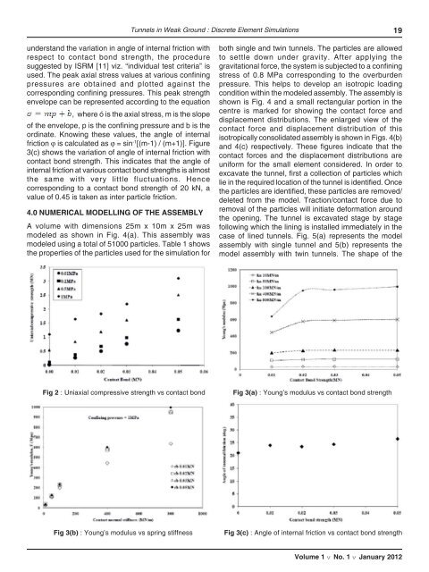
Tunnels in Weak Ground : Discrete Element Simulations19understand the variation in angle of internal friction withrespect to contact bond strength, the proceduresuggested by <strong>ISRM</strong> [11] viz. “individual test criteria” isused. The peak axial stress values at various confiningpressures are obtained and plotted against thecorresponding confining pressures. This peak strengthenvelope can be represented according to the equation, where ó is the axial stress, m is the slopeof the envelope, p is the confining pressure and b is theordinate. Knowing these values, the angle of internalfriction ϕ is calculated as ϕ = sin -1 [(m-1) / (m+1)]. Figure3(c) shows the variation of angle of internal friction withcontact bond strength. This indicates that the angle ofinternal friction at various contact bond strengths is almostthe same with very little fluctuations. Hencecorresponding to a contact bond strength of 20 kN, avalue of 0.45 is taken as inter particle friction.4.0 NUMERICAL MODELLING OF THE ASSEMBLYA volume with dimensions 25m x 10m x 25m wasmodeled as shown in Fig. 4(a). This assembly wasmodeled using a total of 51000 particles. Table 1 showsthe properties of the particles used for the simulation forboth single and twin tunnels. The particles are allowedto settle down under gravity. After applying thegravitational force, the system is subjected to a confiningstress of 0.8 MPa corresponding to the overburdenpressure. This helps to develop an isotropic loadingcondition within the modeled assembly. The assembly isshown is Fig. 4 and a small rectangular portion in thecentre is marked for showing the contact force anddisplacement distributions. The enlarged view of thecontact force and displacement distribution of thisisotropically consolidated assembly is shown in Figs. 4(b)and 4(c) respectively. These figures indicate that thecontact forces and the displacement distributions areuniform for the small element considered. In order toexcavate the tunnel, first a collection of particles whichlie in the required location of the tunnel is identified. Oncethe particles are identified, these particles are removed/deleted from the model. Traction/contact force due toremoval of the particles will initiate deformation aroundthe opening. The tunnel is excavated stage by stagefollowing which the lining is installed immediately in thecase of lined tunnels. Fig. 5(a) represents the modelassembly with single tunnel and 5(b) represents themodel assembly with twin tunnels. The shape of theFig 2 : Uniaxial compressive strength vs contact bondFig 3(a) : Young’s modulus vs contact bond strengthFig 3(b) : Young’s modulus vs spring stiffnessFig 3(c) : Angle of internal friction vs contact bond strengthVolume 1 v No. 1 v January 2012