ISSN - ISRM
ISSN - ISRM
ISSN - ISRM

You also want an ePaper? Increase the reach of your titles
YUMPU automatically turns print PDFs into web optimized ePapers that Google loves.
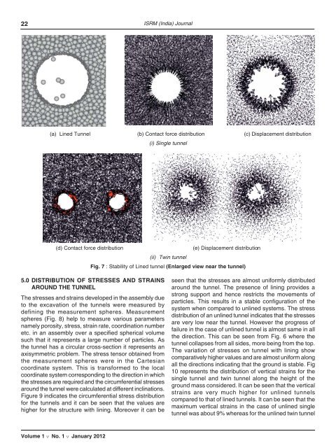
22 <strong>ISRM</strong> (India) Journal(a) Lined Tunnel (b) Contact force distribution (c) Displacement distribution(i) Single tunnel(d) Contact force distribution(e) Displacement distribution(ii) Twin tunnelFig. 7 : Stability of Lined tunnel (Enlarged view near the tunnel)5.0 DISTRIBUTION OF STRESSES AND STRAINSAROUND THE TUNNELThe stresses and strains developed in the assembly dueto the excavation of the tunnels were measured bydefining the measurement spheres. Measurementspheres (Fig. 8) help to measure various parametersnamely porosity, stress, strain rate, coordination numberetc. in an assembly over a specified spherical volumesuch that it represents a large number of particles. Asthe tunnel has a circular cross-section it represents anaxisymmetric problem. The stress tensor obtained fromthe measurement spheres were in the Cartesiancoordinate system. This is transformed to the localcoordinate system corresponding to the direction in whichthe stresses are required and the circumferential stressesaround the tunnel were calculated at different inclinations.Figure 9 indicates the circumferential stress distributionfor the tunnels and it can be seen that the values arehigher for the structure with lining. Moreover it can beseen that the stresses are almost uniformly distributedaround the tunnel. The presence of lining provides astrong support and hence restricts the movements ofparticles. This results in a stable configuration of thesystem when compared to unlined systems. The stressdistribution of an unlined tunnel indicates that the stressesare very low near the tunnel. However the progress offailure in the case of unlined tunnel is almost same in allthe direction. This can be seen from Fig. 6 where thetunnel collapses from all sides, more being from the top.The variation of stresses on tunnel with lining showcomparatively higher values and are almost uniform alongall the directions indicating that the ground is stable. Fig10 represents the distribution of vertical strains for thesingle tunnel and twin tunnel along the height of theground mass considered. It can be seen that the verticalstrains are very much higher for unlined tunnelscompared to that of lined tunnels. It can be seen that themaximum vertical strains in the case of unlined singletunnel was about 9% whereas for the unlined twin tunnelVolume 1 v No. 1 v January 2012