260526 Grounding and Bonding - Electrical Design Guide.docx
260526 Grounding and Bonding - Electrical Design Guide.docx
260526 Grounding and Bonding - Electrical Design Guide.docx

Create successful ePaper yourself
Turn your PDF publications into a flip-book with our unique Google optimized e-Paper software.
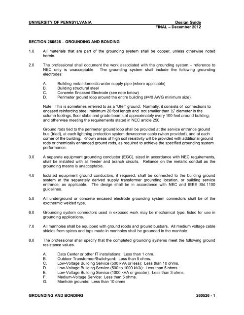
UNIVERSITY OF PENNSYLVANIA<strong>Design</strong> <strong>Guide</strong>FINAL – December 2012SECTION <strong>260526</strong> – GROUNDING AND BONDING1.0 All materials that are part of the grounding system shall be copper, unless otherwise notedherein.2.0 The professional shall document the work associated with the grounding system – reference toNEC only is unacceptable. The grounding system shall include the following groundingelectrodes:A. Building metal domestic water supply pipe (where applicable)B. Building structural steelC. Concrete Encased Electrode (see note below)D. Perimeter ground loop around the entire building (#4/0 AWG minimum size).Note: This is sometimes referred to as a “Ufer” ground. Normally, it consists of connections toencased reinforcing steel, minimum 20 foot length <strong>and</strong> not smaller than ½” diameter in thecolumn footings, floor slabs <strong>and</strong> grade beams at approximately every 100 feet around building,<strong>and</strong> otherwise meeting the requirements stated in NEC article 250.Ground rods tied to the perimeter ground loop shall be provided at the service entrance groundbus (triad), at each lightning protection system downcomer cable (when provided), <strong>and</strong> at eachcorner of the building. Known areas of high soil resistivity will be provided with additional groundrods or chemically enhanced ground rods, as required to achieve the specified grounding systemperformance.3.0 A separate equipment grounding conductor (EGC), sized in accordance with NEC requirements,shall be installed with all feeder <strong>and</strong> branch circuits. Reliance on the metallic conduit as thegrounding means is unacceptable.4.0 Isolated equipment ground conductors, if required, shall be connected to the building groundsystem at the separately derived supply transformer grounding location, or building serviceentrance, as applicable. The design shall be in accordance with NEC <strong>and</strong> IEEE Std.1100guidelines.5.0 All underground or concrete encased electrode grounding system connectors shall be of theexothermic welded type.6.0 <strong>Grounding</strong> system connectors used in exposed work may be mechanical type, listed for use ingrounding applications.7.0 All manholes shall be equipped with ground roods <strong>and</strong> ground busbars. All medium voltage cableshields from spices <strong>and</strong> taps made in manholes shall be grounded in the manhole.8.0 The professional shall specify that the completed grounding systems meet the following groundresistance values.A. Data Center or other IT installations: Less than 1 ohm.B. Outdoor Transformer/Switchyard: Less than 5 ohms.C. Low@Voltage Building Service (500 kVA or less): Less than 10 ohms.D. Low@Voltage Building Service (500 to 1000 kVA): Less than 5 ohms.E. Low@Voltage Building Service (1000 kVA or greater): Less than 3 ohms.F. Medium@Voltage Service: Less than 5 ohms.G. Manhole grounds: Less than 10 ohmsGROUNDING AND BONDING <strong>260526</strong> $ 1
UNIVERSITY OF PENNSYLVANIA<strong>Design</strong> <strong>Guide</strong>FINAL – December 2012Ground resistance testing shall be performed using the fall@of@potential method in accordancewith IEEE St<strong>and</strong>ard 819.0 Testing of the system shall be documented as part of the construction turnover materials, to verifyconformance to design performance requirements. Include the following:A. Perform a megger test using the “Fall@of@Potential Method” to determine that the properground resistance has been achieved, <strong>and</strong> submit a written report of the megger test ofground resistance. Ensure that sufficient spacing between the test set current probe <strong>and</strong>the grounding electrode under test is achieved.B. Perform ground fault protection system functional testing for each 480@volt switchboardhaving ground fault protection <strong>and</strong> for any generator system.C. Perform ground continuity <strong>and</strong> functional tests:1. From main switchgear to grounding electrode <strong>and</strong>/or cold water main.2. Between each main secondary feeder switchboard ground <strong>and</strong> its terminationpoint (distribution panels, panelboards, motor control centers, UPS systems,electric heater disconnects, chiller starters, <strong>and</strong> other such equipment) <strong>and</strong> allfeeders shown on single@line diagram.3. Between each distribution panel to panelboards <strong>and</strong> between each panelboard topanelboard (excluding branch circuits).4. Test each branch circuit receptacle for proper polarity <strong>and</strong> ground using a plug@intest device.10.0 Site design shall include test wells for underground grounding loop in at least two (2) locations.GROUNDING AND BONDING <strong>260526</strong> $ 2