Operating instructions - EWM Hightec Welding GmbH
Operating instructions - EWM Hightec Welding GmbH
Operating instructions - EWM Hightec Welding GmbH

You also want an ePaper? Increase the reach of your titles
YUMPU automatically turns print PDFs into web optimized ePapers that Google loves.
<strong>Operating</strong> <strong>instructions</strong>Air-cooling units for water-cooled welding torchesGBcool35 U31cool71 U42cool71 U43Observe additional system documents!099-008091-EW501 11.11.2011
General <strong>instructions</strong>CAUTIONRead the operating <strong>instructions</strong>!The operating <strong>instructions</strong> provide an introduction to the safe use of the products.• Read the operating <strong>instructions</strong> for all system components!• Observe accident prevention regulations!• Observe all local regulations!• Confirm with a signature where appropriate.NOTEIn the event of queries on installation, commissioning, operation or special conditions at theinstallation site, or on usage, please contact your sales partner or ourcustomer service department on +49 2680 181-0.A list of authorised sales partners can be found at www.ewm-group.com.Liability relating to the operation of this equipment is restricted solely to the function of the equipment. No otherform of liability, regardless of type, shall be accepted. This exclusion of liability shall be deemed accepted by theuser on commissioning the equipment.The manufacturer is unable to monitor whether or not these <strong>instructions</strong> or the conditions and methods areobserved during installation, operation, usage and maintenance of the equipment.An incorrectly performed installation can result in material damage and injure persons as a result. For this reason,we do not accept any responsibility or liability for losses, damages or costs arising from incorrect installation,improper operation or incorrect usage and maintenance or any actions connected to this in any way.© <strong>EWM</strong> HIGHTEC WELDING <strong>GmbH</strong> · Dr. Günter-Henle-Str. 8 · D-56271 Mündersbach, GermanyThe copyright to this document remains the property of the manufacturer.Reprinting, including extracts, only permitted with written approval.Subject to technical amendments.
ContentsNotes on the use of these operating <strong>instructions</strong>1 Contents1 Contents..................................................................................................................................................32 Safety <strong>instructions</strong>.................................................................................................................................42.1 Notes on the use of these operating <strong>instructions</strong> ..........................................................................42.2 Explanation of icons.......................................................................................................................52.3 General ..........................................................................................................................................62.4 Transport and installation ..............................................................................................................92.5 Ambient conditions.......................................................................................................................102.5.1 In operation...................................................................................................................102.5.2 Transport and storage ..................................................................................................103 Intended use .........................................................................................................................................113.1 Applications..................................................................................................................................113.1.1 For operation only with the following equipment ..........................................................113.2 Documents which also apply .......................................................................................................123.2.1 Warranty .......................................................................................................................123.2.2 Declaration of Conformity.............................................................................................123.2.3 <strong>Welding</strong> in environments with increased electrical hazards.........................................123.2.4 Service documents (spare parts and circuit diagrams)................................................124 Machine description – quick overview ..............................................................................................134.1 cool35 U31...................................................................................................................................134.1.1 Front view .....................................................................................................................134.1.2 Rear view......................................................................................................................144.2 cool71 U42, cool71 U43 ..............................................................................................................154.2.1 Front view .....................................................................................................................154.2.2 Rear view......................................................................................................................165 Design and function.............................................................................................................................175.1 Installation....................................................................................................................................175.2 Machine cooling...........................................................................................................................175.3 Cooling module assembly/disassembly.......................................................................................185.3.1 Cooling module assembly ............................................................................................185.3.2 Cooling module disassembly........................................................................................195.4 Connecting the supply lines.........................................................................................................205.5 Coolant.........................................................................................................................................215.5.1 General.........................................................................................................................215.5.2 List of coolants..............................................................................................................215.5.3 Adding coolant..............................................................................................................225.6 Cooling unit function specification ...............................................................................................226 Maintenance, care and disposal.........................................................................................................236.1 General ........................................................................................................................................236.2 Maintenance work, intervals ........................................................................................................236.2.1 Daily maintenance tasks ..............................................................................................236.2.2 Monthly maintenance tasks..........................................................................................236.2.3 Annual test (inspection and testing during operation)..................................................236.3 Maintenance work........................................................................................................................246.4 Disposing of equipment ...............................................................................................................246.4.1 Manufacturer's declaration to the end user..................................................................246.5 Meeting the requirements of RoHS .............................................................................................247 Rectifying faults ...................................................................................................................................257.1 Customer checklist.......................................................................................................................257.2 Vent coolant circuit.......................................................................................................................268 Technical data ......................................................................................................................................278.1 cool35 U31; cool71 U42; cool71 U43 ..........................................................................................279 Accessories ..........................................................................................................................................289.1 General accessories ....................................................................................................................2810 Appendix A ...........................................................................................................................................2910.1 Overview of <strong>EWM</strong> branches ........................................................................................................29099-008091-EW50111.11.20113
Safety <strong>instructions</strong>Notes on the use of these operating <strong>instructions</strong>2 Safety <strong>instructions</strong>2.1 Notes on the use of these operating <strong>instructions</strong>DANGERWorking or operating procedures which must be closely observed to prevent imminentserious and even fatal injuries.• Safety notes include the "DANGER" keyword in the heading with a general warning symbol.• The hazard is also highlighted using a symbol on the edge of the page.WARNINGWorking or operating procedures which must be closely observed to prevent seriousand even fatal injuries.• Safety notes include the "WARNING" keyword in the heading with a general warningsymbol.• The hazard is also highlighted using a symbol in the page margin.CAUTIONWorking or operating procedures which must be closely observed to prevent possibleminor personal injury.• The safety information includes the "CAUTION" keyword in its heading with a generalwarning symbol.• The risk is explained using a symbol on the edge of the page.CAUTIONWorking and operating procedures which must be followed precisely to avoid damagingor destroying the product.• The safety information includes the "CAUTION" keyword in its heading without a generalwarning symbol.• The hazard is explained using a symbol at the edge of the page.NOTESpecial technical points which users must observe.• Notes include the "NOTE" keyword in the heading without a general warning symbol.Instructions and lists detailing step-by-step actions for given situations can be recognised via bulletpoints, e.g.:• Insert the welding current lead socket into the relevant socket and lock.4099-008091-EW50111.11.2011
Safety <strong>instructions</strong>Explanation of icons2.2 Explanation of iconsSymbolDescriptionPressDo not pressTurnSwitch0lSwitch off machine0lSwitch on machineENTER (enter the menu)NAVIGATION (Navigating in the menu)EXIT (Exit the menu)Time display (example: wait 4s/press)Interruption in the menu display (other setting options possible)Tool not required/do not useTool required/use099-008091-EW50111.11.20115
Safety <strong>instructions</strong>General2.3 GeneralDANGERDo not carry out any unauthorised repairs or modifications!To avoid injury and equipment damage, the unit must only be repaired or modified byspecialist, skilled persons!The warranty becomes null and void in the event of unauthorised interference.• Appoint only skilled persons for repair work (trained service personnel)!WARNINGValidity of this document!This document is only valid in combination with the operating <strong>instructions</strong> for thepower source being used (welding machine)!• Read the operating <strong>instructions</strong>, in particular the safety <strong>instructions</strong> for the power source(welding machine)!Risk of accidents if these safety <strong>instructions</strong> are not observed!Non-observance of these safety <strong>instructions</strong> is potentially fatal!• Carefully read the safety information in this manual!• Observe the accident prevention regulations in your country.• Inform persons in the working area that they must observe the regulations!Hazards due to improper usage!Hazards may arise for persons, animals and material objects if the equipment is notused correctly. No liability is accepted for any damages arising from improper usage!• The equipment must only be used in line with proper usage and by trained or expert staff!• Do not modify or convert the equipment improperly!CAUTIONObligations of the operator!The respective national directives and laws must be observed for operation of themachine!• National implementation of the framework directive (89/391/EWG), as well as theassociated individual directives.• In particular, directive (89/655/EWG), on the minimum regulations for safety and healthprotection when staff members use equipment during work.• The regulations regarding work safety and accident prevention for the respective country.• Setting up and operating the machine according to IEC 60974-9.• Check at regular intervals that users are working in a safety-conscious way.• Regular checks of the machine according to IEC 60974-4.6099-008091-EW50111.11.2011
Safety <strong>instructions</strong>GeneralCAUTIONDamage due to the use of non-genuine parts!The manufacturer's warranty becomes void if non-genuine parts are used!• Only use system components and options (power sources, welding torches, electrodeholders, remote controls, spare parts and replacement parts, etc.) from our range ofproducts!• Only insert and lock accessory components into the relevant connection socket when themachine is switched off.Damage to the machine due to stray welding currents!Stray welding currents can destroy protective earth conductors, damage equipment andelectronic devices and cause overheating of components leading to fire.• Make sure all welding leads are securely connected and check regularly.• Always ensure a proper and secure electrical connection to the workpiece!• Set up, attach or suspend all conductive power source components like casing, transportvehicle and crane frames so they are insulated!• Do not place any other electronic devices such as drillers or angle grinders, etc., on thepower source, transport vehicle or crane frames unless they are insulated!• Always put welding torches and electrode holders on an insulated surface when they arenot in use!Mains connectionRequirements for connection to the public mains networkHigh-performance machines can influence the mains quality by taking current from the mainsnetwork. For some types of machines, connection restrictions or requirements relating to themaximum possible line impedance or the necessary minimum supply capacity at the interfacewith the public network (Point of Common Coupling, PCC) can therefore apply. In this respect,attention is also drawn to the machines' technical data. In this case, it is the responsibility ofthe operator, where necessary in consultation with the mains network operator, to ensure thatthe machine can be connected.099-008091-EW50111.11.20117
Safety <strong>instructions</strong>GeneralCAUTIONEMC Machine ClassificationIn accordance with IEC 60974-10, welding machines are grouped in two electromagneticcompatibility classes (see technical data):Class A machines are not intended for use in residential areas where the power supply comesfrom the low-voltage public mains network. When ensuring the electromagnetic compatibility ofclass A machines, difficulties can arise in these areas due to interference not only in the supplylines but also in the form of radiated interference.Class B machines fulfil the EMC requirements in industrial as well as residential areas,including residential areas connected to the low-voltage public mains network.Setting up and operatingWhen operating arc welding systems, in some cases, electro-magnetic interference can occuralthough all of the welding machines comply with the emission limits specified in the standard.The user is responsible for any interference caused by welding.In order to evaluate any possible problems with electromagnetic compatibility in thesurrounding area, the user must consider the following: (see also EN 60974-10 Appendix A)• Mains, control, signal and telecommunication lines• Radios and televisions• Computers and other control systems• Safety equipment• The health of neighbouring persons, especially if they have a pacemaker or wear a hearingaid• Calibration and measuring equipment• The immunity to interference of other equipment in the surrounding area• The time of day at which the welding work must be carried outRecommendations for reducing interference emission• Mains connection, e.g. additional mains filter or shielding with a metal tube• Maintenance of the arc welding equipment• <strong>Welding</strong> leads should be as short as possible and run closely together along the ground• Potential equalization• Earthing of the workpiece. In cases where it is not possible to earth the workpiece directly,it should be connected by means of suitable capacitors.• Shielding from other equipment in the surrounding area or the entire welding system8099-008091-EW50111.11.2011
Safety <strong>instructions</strong>Transport and installation2.4 Transport and installationWARNINGRisk of accident due to improper transport of machines that may not be lifted!Do not lift or suspend the machine! The machine can fall down and cause injuries! Thehandles and brackets are suitable for transport by hand only!• The machine may not be lifted by crane or suspended!CAUTIONRisk of tipping!There is a risk of the machine tipping over and injuring persons or being damaged itselfduring movement and set up. Tilt resistance is guaranteed up to an angle of 10°(according to EN 60974-A2).• Set up and transport the machine on level, solid ground!• Secure add-on parts using suitable equipment!• Replace damaged wheels and their fixing elements!• Fix external wire feed units during transport (avoid uncontrolled rotation)!Damage due to supply lines not being disconnected!During transport, supply lines which have not been disconnected (mains supply leads,control leads, etc.) may cause hazards such as connected equipment tipping over andinjuring persons!• Disconnect supply lines!CAUTIONEquipment damage when not operated in an upright position!The units are designed for operation in an upright position!Operation in non-permissible positions can cause equipment damage.• Only transport and operate in an upright position!099-008091-EW50111.11.20119
Safety <strong>instructions</strong>Ambient conditions2.5 Ambient conditionsCAUTIONEquipment damage due to dirt accumulation!Unusually high quantities of dust, acid, corrosive gases or substances may damage theequipment.• Avoid high volumes of smoke, vapour, oil vapour and grinding dust!• Avoid ambient air containing salt (sea air)!Non-permissible ambient conditions!Insufficient ventilation results in a reduction in performance and equipment damage.• Observe the ambient conditions!• Keep the cooling air inlet and outlet clear!• Observe the minimum distance of 0.5 m from obstacles!2.5.1 In operationTemperature range of the ambient air:• During welding: -20 °C to +40° C *• During transport and storage: -25 °C to +55 °C ** depending on coolantRelative air humidity:• Up to 50% at 40 °C• Up to 90% at 20 °C2.5.2 Transport and storageStorage in an enclosed space, temperature range of the ambient air:• -25 °C to +55 °CRelative air humidity• Up to 90% at 20 °C10099-008091-EW50111.11.2011
Intended useApplications3 Intended useThis machine has been manufactured according to the latest developments in technology and currentregulations and standards. It must only be operated in line with the <strong>instructions</strong> on correct usage.WARNINGHazards due to improper usage!Hazards may arise for persons, animals and material objects if the equipment is notused correctly. No liability is accepted for any damages arising from improper usage!• The equipment must only be used in line with proper usage and by trained or expert staff!• Do not modify or convert the equipment improperly!3.1 ApplicationsThese cooling modules are designed solely for cooling welding torches.We can only guarantee smooth and trouble-free operation when used in conjunction with the weldingmachines, welding torches, coolants and accessory components from our range.3.1.1 For operation only with the following equipmentcool35 U31 cool71 U42 cool71 U43alpha Q 330 Phoenix 330 Puls Tetrix 300 Tetrix 300 AC/DC Tetrix 400-2 Tetrix 150, 300, 400 Plasma Tetrix 350 AC/DC Plasma 099-008091-EW50111.11.201111
Intended useDocuments which also apply3.2 Documents which also apply3.2.1 WarrantyNOTEFor further information, please see the accompanying supplementary sheets "Machineand Company Data, Maintenance and Testing, Warranty"!3.2.2 Declaration of ConformityThe designated machine conforms to EC Directives and standards in terms of its designand construction:• EC Low Voltage Directive (2006/95/EC),• EC EMC Directive (2004/108/EC),This declaration shall become null and void in the event of unauthorised modifications, improperlyconducted repairs, non-observance of the deadlines for the repetition test and / or non-permittedconversion work not specifically authorised by the manufacturer.The original copy of the declaration of conformity is enclosed with the unit.3.2.3 <strong>Welding</strong> in environments with increased electrical hazardsIn compliance with IEC / DIN EN 60974, VDE 0544 the machines can be used inenvironments with an increased electrical hazard.3.2.4 Service documents (spare parts and circuit diagrams)DANGERDo not carry out any unauthorised repairs or modifications!To avoid injury and equipment damage, the unit must only be repaired or modified byspecialist, skilled persons!The warranty becomes null and void in the event of unauthorised interference.• Appoint only skilled persons for repair work (trained service personnel)!Original copies of the circuit diagrams are enclosed with the unit.Spare parts can be obtained from the relevant authorised dealer.12099-008091-EW50111.11.2011
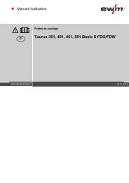
4 Machine description – quick overview4.1 cool35 U314.1.1 Front viewMachine description – quick overviewcool35 U31Item Symbol Description 0Figure 4-11 Tension bracket closureConnection between the cooling unit and the welding machine2 Coolant tank cap3 Coolant tank4 Quick connect coupling, redCoolant return from the welding torch5 Quick connect coupling, blueCoolant supply to the welding torch6 Cooling air inlet7 Machine feet099-008091-EW50111.11.201113
Machine description – quick overviewcool35 U314.1.2 Rear viewItem Symbol Description 0Figure 4-21 Connector plug, 4-poleCooling unit voltage supply2 Connector plug, 8-poleCooling unit control lead3 Cooling air outlet4 Coolant drain hoseDevice for draining the coolant5 Automatic cut-out of coolant pump key buttonpress to reset a triggered fuse14099-008091-EW50111.11.2011
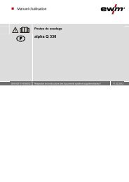
Machine description – quick overviewcool71 U42, cool71 U434.2 cool71 U42, cool71 U434.2.1 Front viewItem Symbol Description 0Figure 4-31 Tension bracket closureConnection between the cooling unit and the welding machine2 Carrying handle3 Coolant tank cap4 Coolant tank5 Cooling air inlet6 Quick connect coupling, redCoolant return from the welding torch7 Quick connect coupling, blueCoolant supply to the welding torch8 Machine feet099-008091-EW50111.11.201115
Machine description – quick overviewcool71 U42, cool71 U434.2.2 Rear viewItem Symbol Description 0Figure 4-41 Quick connect coupling, blueCoolant supply to the welding machine or wire feed unit2 Quick connect coupling, redCoolant return from the welding machine or wire feed unit3 Automatic cut-out of coolant pump key buttonpress to reset a triggered fuse4 Coolant drain hoseDevice for draining the coolant5 Cooling air outlet6 Connector plug, 4-poleCooling unit voltage supply7 Connector plug, 8-poleCooling unit control lead16099-008091-EW50111.11.2011
Design and functionInstallation5 Design and functionWARNINGRisk of injury from electric shock!Contact with live parts, e.g. welding current sockets, is potentially fatal!• Follow safety <strong>instructions</strong> on the opening pages of the operating <strong>instructions</strong>.• Commissioning may only be carried out by persons who have the relevant expertise ofworking with arc welding machines!• Connection and welding leads (e.g. electrode holder, welding torch, workpiece lead,interfaces) may only be connected when the machine is switched off!NOTEObserve documentation of other system components when connecting!5.1 InstallationWARNINGRisk of accident due to improper transport of machines that may not be lifted!Do not lift or suspend the machine! The machine can fall down and cause injuries! Thehandles and brackets are suitable for transport by hand only!• The machine may not be lifted by crane or suspended!CAUTIONInstallation site!The machine must not be operated in the open air and must only be set up andoperated on a suitable, stable and level base!• The operator must ensure that the ground is non-slip and level, and provide sufficientlighting for the place of work.• Safe operation of the machine must be guaranteed at all times.CAUTIONDamage to the machine due to improper transport!The machine can be damaged by tensile or lateral forces if it is setdown or picked up in a non-vertical position!• Do not drag the machine horizontally on the machine feet!• Always pick up the machine vertically and set it down carefully.5.2 Machine coolingTo obtain an optimal duty cycle from the power components, the following precautions should beobserved:• Ensure that the working area is adequately ventilated.• Do not obstruct the air inlets and outlets of the machine.• Do not allow metal parts, dust or other objects to get into the machine.099-008091-EW50111.11.201117
Design and functionCooling module assembly/disassembly5.3 Cooling module assembly/disassemblyCAUTIONDamage due to supply lines not being disconnected!During transport, supply lines which have not been disconnected (mains supply leads,control leads, etc.) may cause hazards such as connected equipment tipping over andinjuring persons!• Disconnect supply lines!NOTEAssembly and disassembly is very simple and doesn't require any tools.5.3.1 Cooling module assembly12Figure 5-1Item Symbol Description 01 Locking hook2 Butterfly handle• Lift the wing-tip handles on the tension bracket closure (A2) and turn anti-clockwise (B2) until thelocking hook is extended.Figure 5-2• Position the welding machine on the module as shown in fig.18099-008091-EW50111.11.2011
Design and functionCooling module assembly/disassembly12Figure 5-3• Turn the wing-tip handle clockwise (B2) to close the fastening.• Engage the locking hook in the recesses in the side walls of the welding machine.12Figure 5-4• Lay the wing-tip handle down flat (C2).5.3.2 Cooling module disassembly• Lift the wing-tip handle and turn anti-clockwise until the locking hook is extended.• Lift the locking hook out of the recesses on the welding machine.• The welding machine can be lifted off the cooling unit.099-008091-EW50111.11.201119
Design and functionConnecting the supply lines5.4 Connecting the supply linesWARNINGRisk of injury from electric shock!Contact with live parts, e.g. welding current sockets, is potentially fatal!• Follow safety <strong>instructions</strong> on the opening pages of the operating <strong>instructions</strong>.• Commissioning may only be carried out by persons who have the relevant expertise ofworking with arc welding machines!• Connection and welding leads (e.g. electrode holder, welding torch, workpiece lead,interfaces) may only be connected when the machine is switched off!CAUTIONOverloading the coolant pump!The cooling unit must not be put into operation without a welding torch connected, asotherwise the coolant pump will be destroyed due to thermal overload (the coolantcannot circulate in the coolant circuit).• Connect the coolant connections for the water cooled welding torch to the cooling module.• If air-cooled welding torches are used, the control and supply line between the coolingmodule and welding machine must be disconnected!NOTEReserve length for control and supply cable!When using high systems such as AC/DC machines or systems with several modules(welding machine + multivoltage module + cooling module) the cable length has to beadapted.To do so, loosen the knurled nuts of the strain reliefs for the control and supply cablesat the back of the machine. Pull out both connection cables slowly and evenly for alength of approx. 120 mm. Screw both strain reliefs tight again.Coolant connections• Plug in the welding torch coolant connections and fit tightly onto the rapid-action closure couplings:red rapid-action closure coupling return of coolant from the welding torchblue rapid-action closure coupling supply of coolant to the welding torch.Control and supply lead to the welding machine• The cooling module and welding machine are connected using two leads.• Insert control lead plug into the welding machine.• Insert supply lead plug into the welding machine.20099-008091-EW50111.11.2011
Design and functionCoolant5.5 Coolant5.5.1 GeneralCAUTIONCoolant mixtures!Mixtures with other liquids or the use of unsuitable coolants result in material damageand renders the manufacturer's warranty void!• Only use the coolant described in this manual (overview of coolants).• Do not mix different coolants.• When changing the coolant, the entire volume of liquid must be changed.Insufficient frost protection in the welding torch coolant!Depending on the ambient conditions, different liquids are used for cooling the weldingtorch (see overview of coolants).Coolants with frost protection (KF 37E or KF 23E) must be checked regularly to ensurethat the frost protection is adequate to prevent damage to the machine or the accessorycomponents.• The coolant must be checked for adequate frost protection with the TYP 1 frost protectiontester (see accessories).• Replace coolant as necessary if frost protection is inadequate!NOTEThe disposal of coolant must be carried out according to official regulations andobserving the relevant safety data sheets (German waste code number: 70104)!• Coolant must not be disposed of together with household waste.• Coolant must not be discharged into the sewerage system.• Recommended cleaning agent: water, if necessary with cleaning agent added.5.5.2 List of coolantsThe following coolants may be used (for item nos., please see the Accessories chapter):CoolantTemperature rangeKF 23E (Standard) -10 °C to +40 °CKF 37E -20 °C to +10 °CDKF 23E (for plasma machines) 0 °C to +40 °C099-008091-EW50111.11.201121
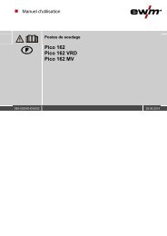
Design and functionCooling unit function specification5.5.3 Adding coolantNOTEAfter the initial filling, wait for at least one minute when the machine is switched on sothat the tube package is filled with coolant completely and without bubbles.With frequent changes of torch and during the initial filling process, the cooling unittank should be topped up as necessary.The unit is supplied ex works with a minimum level of coolant.Item Symbol Description 01 Coolant tank cap2 Coolant filter sieve3 Coolant tank4 "Min" markMinimum coolant levelFigure 5-5• Unscrew and remove the coolant tank sealing cover.• Check filter sieve insert for dirt, clean if necessary and reinsert into position.• Top up coolant to the filter sieve insert, close sealing cover again.NOTEThe level of coolant must never fall below the “min” mark.5.6 Cooling unit function specificationThe cooling modules (pump and fan) are controlled by the welding machine only.The welding machine automatically detects and displays a lack of coolant(see the welding machine operating <strong>instructions</strong>).22099-008091-EW50111.11.2011
Maintenance, care and disposalMaintenance work6.3 Maintenance workDANGERDo not carry out any unauthorised repairs or modifications!To avoid injury and equipment damage, the unit must only be repaired or modified byspecialist, skilled persons!The warranty becomes null and void in the event of unauthorised interference.• Appoint only skilled persons for repair work (trained service personnel)!Repair and maintenance work may only be performed by qualified authorised personnel; otherwise theright to claim under warranty is void. In all service matters, always consult the dealer who supplied themachine. Return deliveries of defective equipment subject to warranty may only be made through yourdealer. When replacing parts, use only original spare parts. When ordering spare parts, please quote themachine type, serial number and item number of the machine, as well as the type designation and itemnumber of the spare part.6.4 Disposing of equipmentNOTEProper disposal!The machine contains valuable raw materials, which should be recycled, andelectronic components, which must be disposed of.• Do not dispose of in household waste!• Observe the local regulations regarding disposal!6.4.1 Manufacturer's declaration to the end user• According to European provisions (guideline 2002/96/EG of the European Parliament and the Councilof January, 27th 2003), used electric and electronic equipment may no longer be placed in unsortedmunicipal waste. It must be collected separately. The symbol depicting a waste container on wheelsindicates that the equipment must be collected separately.This machine is to be placed for disposal or recycling in the waste separation systems provided for thispurpose.• According to German law (law governing the distribution, taking back and environmentally correctdisposal of electric and electronic equipment (ElektroG) from 16.03.2005), used machines are to beplaced in a collection system separate from unsorted municipal waste. The public waste managementutilities (communities) have created collection points at which used equipment from private householdscan be disposed of free of charge.• Information about giving back used equipment or about collections can be obtained from therespective municipal administration office.• <strong>EWM</strong> participates in an approved waste disposal and recycling system and is registered in the UsedElectrical Equipment Register (EAR) under number WEEE DE 57686922.• In addition to this, returns are also possible throughout Europe via <strong>EWM</strong> sales partners.6.5 Meeting the requirements of RoHSWe, <strong>EWM</strong> HIGHTEC <strong>Welding</strong> <strong>GmbH</strong> Mündersbach, hereby confirm that all products supplied by us whichare affected by the RoHS Directive, meet the requirements of the RoHS (Directive 2002/95/EC).24099-008091-EW50111.11.2011
Rectifying faultsCustomer checklist7 Rectifying faultsAll products are subject to rigorous production checks and final checks. If, despite this, something fails towork at any time, please check the product using the following flowchart. If none of the fault rectificationprocedures described leads to the correct functioning of the product, please inform your authoriseddealer.7.1 Customer checklistLegend: Fault/Cause: RemedyNOTEThe correct machine equipment for the material and process gas in use is afundamental requirement for perfect operation!Please observe the welding machine operating <strong>instructions</strong>.Coolant error/no coolant flowing Insufficient coolant flow Check coolant level and refill if necessary Eliminate kinks in conduit system (hose packages) Extend and lay out the torch hose package Reset automatic cutout of the coolant pump by activating Air in the coolant circuit see chapter "Vent coolant circuit" Coolant pump blocked see chapter "Fixing the pump shaft"Functional errors Connection problems Make control lead connections and check that they are fitted correctly.099-008091-EW50111.11.201125
Rectifying faultsVent coolant circuit7.2 Vent coolant circuitNOTEIf there is less coolant in the coolant tank than the minimum required you may need tovent the coolant circuit. In this case the welding machine will automatically shut downthe coolant pump and signal an error, see chapter "Rectifying faults".To vent the cooling system always use the blue coolant connection, which is located asdeep as possible inside the system (close to the coolant tank)!26099-008091-EW50111.11.2011
Technical datacool35 U31; cool71 U42; cool71 U438 Technical dataNOTETechnical data limit valuesThe limit values determination from technical data is calculated taking account of thecombined system as a whole (cooling unit and welding machine).8.1 cool35 U31; cool71 U42; cool71 U43cool 35 U31 71 U42 71 U43Supply voltage (tolerances)see welding machineMains frequency50/60 HzCooling output 800 W (l/min) 1500 W (2 l/min) 1200 W (1 l/min)Max. flow rate 5 l/min 20 l/min 5 l/minMax. initial coolant• pressure 3.5 bar 4.5 bar 3.5 barMax. tank capacity approx. 4.5 l approx. 7 lDimensions L/W/H in mm 650 x 270 x 225 685 x 335 x 255Cooling mode/protectionF/IP 23classificationWeight (without coolant) 18,7 kg 34,4 kg 25,4 kgEMC classAConstructed to standards IEC 60974-1, -2, -10099-008091-EW50111.11.201127
AccessoriesGeneral accessories9 Accessories9.1 General accessoriesType Designation Item no.TYP 1 Frost protection tester 094-014499-00000KF 23E-10 Coolant (-10 °C), 9.3 l 094-000530-00000KF 23E-200 Coolant (-10 °C), 200 litres 094-000530-00001KF 37E-10 Coolant (-20 °C), 9.3 l 094-006256-00000KF 37E-200 Coolant (-20 °C), 200 l 094-006256-00001DKF10 Deionised coolant, no frost protection 094-001504-0000028099-008091-EW50111.11.2011
Appendix AOverview of <strong>EWM</strong> branches10 Appendix A10.1 Overview of <strong>EWM</strong> branches099-008091-EW50111.11.201129