von Karman Institute for Fluid Dynamics Chaussée de Waterloo, 72 ...
von Karman Institute for Fluid Dynamics Chaussée de Waterloo, 72 ...
von Karman Institute for Fluid Dynamics Chaussée de Waterloo, 72 ...
- No tags were found...

Create successful ePaper yourself
Turn your PDF publications into a flip-book with our unique Google optimized e-Paper software.
<strong>von</strong> <strong>Karman</strong> <strong>Institute</strong> <strong>for</strong> <strong>Fluid</strong> <strong>Dynamics</strong><strong>Chaussée</strong> <strong>de</strong> <strong>Waterloo</strong>, <strong>72</strong>B - 1640 Rho<strong>de</strong> Saint Genèse - BelgiumReprint 2006-14 February 2006WIND POWER IN THE FUTUREBELGIAN ANTARCTIC RESEARCH STATIONJ. Sanz Rodrigo, J. van Beeck, C. Gorle,J. Berte, L. Dewil<strong>de</strong>, Y. Cabooter, F. Pattyn2006 European Wind Energy Conference and Exhibition, February 27, 2006, Athens,Greece
2006 European Wind Energy Conference and Exhibition, Athens (GR) 27-February-2006Wind Power in the future Belgian Antarctic Research StationJavier Sanz Rodrigo, Jeroen van Beeck & Catherine Gorle (VKI 1 )Johan Berte (IPF 2 )Luc Dewil<strong>de</strong> & Yves Cabooter (3E 3 )Frank Pattyn (ULB 4 )1 <strong>von</strong> <strong>Karman</strong> <strong>Institute</strong> <strong>for</strong> <strong>Fluid</strong> <strong>Dynamics</strong>, Environemental and Applied <strong>Fluid</strong> <strong>Dynamics</strong> Department,<strong>Chaussée</strong> <strong>de</strong> <strong>Waterloo</strong> <strong>72</strong>, 1640 Rho<strong>de</strong>-Saint-Genèse, Belgium.sanz@vki.ac.be, vanbeeck@vki.ac.be, gorle@vki.ac.be, Tf:+32 2 359 96 27, Fax: +32 2 359 96 002 The International Polar FoundationRue <strong>de</strong>s Deux Gares, 120A, B-1070 Brussels, Belgiumjohan.berte@polarfoundation.org3 3E nvRue <strong>de</strong> l'Association 39, B-1000 Brussels, BelgiumLuc.Dewil<strong>de</strong>@3E.be, Yves.Cabooter@3e.be4 Université Libre <strong>de</strong> Bruxelles, Départment <strong>de</strong>s Sciences <strong>de</strong> la Terre et <strong>de</strong> l'Environnement,50, av. F.D. Roosevelt, B-1050 Brussels, Belgiumfpattyn@ulb.ac.beSummary (250 words)The new Belgian Research Station will be constructed in the Sor Rondane Mountains, Antarctica, by the end of 2007.The base, currently in its final <strong>de</strong>sign phase, is conceived as a prototype to achieve the minimum environmentalimpact and the highest efficiency in the use of energy resources and waste management, fundamental issues of theAntarctic Environmental Protocol. The integration of renewable energies is a must due to the isolated conditions ofthe site. The resulting station aims at being a reference of the state of the art in sustainable <strong>de</strong>velopment in isolatedareas. The main <strong>de</strong>sign drivers are <strong>de</strong>scribed with special regard to wind power systems. The wind resourceassessment is done using wind atlas methodology and CFD, making use of the historical records at Novolazarevskayastation to predict the long term wind conditions. The selection of the wind turbine mo<strong>de</strong>l is still un<strong>de</strong>r discussion. Alayout maximising the power output from the available terrain is given as a reference <strong>for</strong> a wind turbine mo<strong>de</strong>l of22kW. A feasibility study on this reference case shows that the use of wind power can result 5-10 times morecompetitive than its conventional use in Europe.Sustainable <strong>de</strong>sign of the Belgian Antarctic stationScope of the projectThe site <strong>for</strong> the new station is situated approximately 1 km North of Utsteinen Nunatak, on a small relatively flatgranite ridge (71°57’S 023°20’E, 1390m a.s.l.), 173 km inland from the <strong>for</strong>mer Roi Baudouin base and 55 km fromthe <strong>for</strong>mer Japanese Asuka station. With the closing of Asuka station in 1992, the 20-30 <strong>de</strong>grees east sector ofAntarctica became again a vast territory havingwitnessed up to now only brief periods ofsystematic investigation. The new station will thusNovoreoccupy the 10<strong>72</strong> km empty stretch betweenSyowaSyowa station (684 km) and the Russian stationNovolazarevskaya (431 km).The construction of the summer station is plannedin the austral summer of 2007-2008. In this periodthe station will be built, the system acceptance testper<strong>for</strong>med and then it will be han<strong>de</strong>d over to theBelgian Science Office at the end of the season. Theexpected <strong>de</strong>sign life is 25 years minimum.The new plat<strong>for</strong>m is offered to the Belgian andinternational scientific community in a flexible wayboth operationally and with respect to researchopportunities. The station will serve as a hub <strong>for</strong>field exploration in the 20-30 <strong>de</strong>grees east sector ofAntarctica. The station is <strong>de</strong>signed <strong>for</strong> optimal useby 12 people with a surface area (living, technical,research, storage) of 800 m². The use of a station“extension” will make it possible to accommodateanother 8 to 18 people. This extension consists ofFigure 1: Situation map of the future Belgian AntarcticStation and the nearest permanent stations.1
2006 European Wind Energy Conference and Exhibition, Athens (GR) 27-February-2006heated shelters used <strong>for</strong> sleeping only. The station’s facilities (kitchen, sanitary installations, offices …) are <strong>de</strong>signedto cope with the larger occupation.Figure 2: Southernmost edge of the ridge with the 4m height AWSConsistent with the philosophy of the project, the station <strong>de</strong>sign will make best use of the terrain conditions <strong>for</strong> theintegration of the buildings and will be such that it minimises impact on the environment and on the landscape duringthe construction, operation and removal of the station. The station has a hybrid <strong>de</strong>sign, with the main building aboveground-level and anchored onto snow-free rock area. The adjacent garage/storage building is located nearby and ismainly constructed un<strong>de</strong>r the surrounding snow surface. Both buildings are inter-connected by a weather protectedcorridor. The <strong>de</strong>sign and layout of the facilities will minimise snow management.Sustainable technology <strong>de</strong>signThe use of sustainable technology as the primary energy source, without compromising functionality, com<strong>for</strong>t orsafety <strong>de</strong>mands, implies an integrated <strong>de</strong>sign methodology similar to the one used in applied technology projects (cfr.industry & space). The project management has been structured according to this method. On the conceptual <strong>de</strong>signlevel a verification method with four major lines of approach (environment, human factors including safety,technology and cost) is used to evaluate and steer all conceptual <strong>de</strong>cision making. All prime project partners worktogether from the start of the iterative <strong>de</strong>sign process thereby guaranteeing that the different fields of interest aretaken care of in a homogeneous way. The system <strong>de</strong>sign of the station is based on sustainable technology and highenergy efficiency, with a full-year monitoring and remote sensing capability. Nevertheless safety, health, com<strong>for</strong>t,functionality and cost are equally important <strong>de</strong>sign drivers. The facilities will use renewable energy as the primaryenergy source, integrating a comprehensive energy management regime, thereby minimising the use of fossil fuels.To assure a constant energy supply, two back-up generators will be installed. The amount of fuel used at the stationwill be mainly <strong>for</strong> vehicles.The air-conditioned main building is the living area of the station and has a usable floor space of approximately 350m². The “garage/storage” building accommodates secondary functions such as work shops and storage of suppliesand spare parts. The station will provi<strong>de</strong> an efficient and pleasant living/working environment <strong>for</strong> the crew but theprogramme is also <strong>de</strong>veloped according to energy efficiency needs and the specific technical <strong>de</strong>mands imposed bythe winter close-down of the station.The main building has a concentric architecture laid out around a “technical core”. All temperature-sensitiveinstallations and equipment, such as the waste water treatment system, are concentrated in this area of the building. Asecond concentric layer around the technical core consists of space <strong>for</strong> active systems such as the kitchen, sanitary,laundry and the station’s energy management system. It also has storage <strong>for</strong> fragile office equipment during winter. Athird concentric layer consists of “passive” areas, <strong>for</strong> example, the living and sleeping rooms. Temperature bufferspaces are inclu<strong>de</strong>d below the floor and above the ceiling. The fourth and last of the containment levels is the outershell. This structure consists on a number of passive and active elements such as insulation materials, air-gaps <strong>for</strong>buffering and energy-related systems. For winter close-down each individual layer is “sealed” thereby creating anumber of temperature-controlled buffer zones against the cold exterior environment. This makes it possible tomaintain all layers at a guaranteed minimum temperature with minimal energy supply, protecting installations andwhole year active systems located in the technical core as well as the appliances located in the second layer. The“passive” area (third layer) acts as an additional buffer zone. All building zones will be monitored <strong>for</strong> temperatureroutinely.2
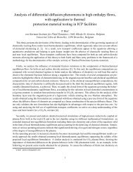
2006 European Wind Energy Conference and Exhibition, Athens (GR) 27-February-2006Figure 3: Impression of the new station at 45 o wind inci<strong>de</strong>nce with a connection bridge withthe un<strong>de</strong>r-snow garage/storage building. The black areas covering the surfaces of the mainbuilding are solar collectors combined with windows. Wind comes from the right.The garage/storage building is an un<strong>de</strong>r-snow surface construction connected by an aerodynamically shaped andweather-protected staircase to the main building, and follows the <strong>de</strong>sign philosophies of minimal environmental andvisual disturbance, best com<strong>for</strong>t and energy efficiency.The water supply <strong>for</strong> the station will use solar thermal panels to melt the snow thereby limiting the use of electricalenergy to pumping the water. In addition electrical heating, eventually backed-up with waste heat originating fromco-generation (multiple sources possible), can be used in the system.The waste water treatment plant consists of a grey and black (black water inclu<strong>de</strong>s urine and human solid waste)water system. The proposed <strong>de</strong>sign minimises water <strong>de</strong>mand by reducing fresh water consumption. Water comingfrom the snow melting facility, stored in a buffer tank, will be used <strong>for</strong> all potable functions, including showers andcooking. Other building functions will use recycled water.The use of sustainable technology as the primary energy source without compromising functionality, com<strong>for</strong>t orsafety requires a cautious approach in the system engineering. Making best use of co-generation and enhancingenergy efficiency implies a high level of integration but this could have a major disadvantage: vulnerability of thewhole system <strong>for</strong> partial break-downs. There<strong>for</strong>e in the conceptual <strong>de</strong>sign the following approach has been used:• Reliability: where possible subsystems are composed of modules built up from proven technology exten<strong>de</strong>dto (relatively) new technology <strong>for</strong> highest efficiency. The minimum functionality of the subsystem isassured by the core system.• In<strong>de</strong>pen<strong>de</strong>ncy: the interaction (e.g. co-generation) of subsystems does not compromise the functioning ofthe individual subsystems.• Redundancy: <strong>de</strong>tailed Failure Mo<strong>de</strong> Effect Analysis (FMEA) analysis of the whole building is used as aninput to the <strong>de</strong>sign process, safety measures, maintenance and other applicable strategies are tailoredaccording to this.Prior to the concept phase of the project an extensive technology survey was conducted looking at potential solutions<strong>for</strong> energy generation, distribution, storage and sustainable energy system in general. Such a survey was also applied<strong>for</strong> most aspects of the building physics such as Heating, Ventilation, Air Conditioning (HVAC)… Brainstorms <strong>for</strong>possible solutions were backed-up by preliminary energy simulations taking into account the on-site weather data(wind/sun/temperature), user (consumer) profiles, user scenarios, materials used, the building geometry andorientation.Wind and snow managementWind conditions have a major impact on the structural aspects of the building but also heavily influence operations,com<strong>for</strong>t and energy efficiency. Aerodynamic testing is used to:• limit the expected snow accumulation in the lee si<strong>de</strong> of the building;• prevent snow accumulation upwind of the building;• control wind-induced <strong>for</strong>ces on the building;• set mechanical engineering specifications;• enhance the com<strong>for</strong>t insi<strong>de</strong> (and outsi<strong>de</strong>) the building by reducing noise and vibrations;• validate the numeric wind mo<strong>de</strong>l to assess wind power potential;• assign positions <strong>for</strong> stand-alone facilities.3
2006 European Wind Energy Conference and Exhibition, Athens (GR) 27-February-2006Figure 4: Wind tunnel testing of snowdrifts using sand (VKI L1-Bwind tunnel: 2m high, 3m wi<strong>de</strong> and 20 m long)The selected <strong>de</strong>sign generates manageable snow accumulation and erosion features <strong>for</strong> the prevalent wind direction.It also prevents snow build-up on the windward si<strong>de</strong> of the building. Such a snow build up would continuouslychange the incoming airflow characteristics creating unpredictable behaviour in terms of long term snowaccumulation. The vortex path generated by the building has positive and negative si<strong>de</strong>-effects <strong>de</strong>pending on therelative position of the garage building and its entrance. The erosion regions are exploited enabling a lowmaintenance entrance.EnergyThe energy generation si<strong>de</strong> of the system consists of different elements that function separately or combined<strong>de</strong>pending on the <strong>de</strong>mands and circumstances. The station site has a sheltered nature but the site still provi<strong>de</strong>ssufficient wind to use wind energy as a major electrical energy source.The concept consists of a number of relatively small wind turbines positioned along the ridge. On the building bothsolar thermal and photovoltaic panels are used. For solar passive energy there are, apart from the strategicallypositioned glazing, also “solar transparent” insulation panels on the roof used <strong>for</strong> pre-heating ventilation air and warmup the thermal masses situated in the building roof buffer zones. The distribution of the different panel types is<strong>de</strong>fined by the user profiles (energy needs) and the position of the sun during the day. The photovoltaic system willbe capable to provi<strong>de</strong> up to 10 % of the electrical load and mainly will reduce the storage capacity in batteries asmuch as possible.A (typical) problem with renewable energy is its intermittent character. The energy stored in the buffer battery packwill be reduced as much as is reasonably feasible by the following measures:• It has been <strong>de</strong>ci<strong>de</strong>d to rely on photovoltaic as well as wind energy production as primary electricity sources.• A fly-wheel will be installed to buffer fast variations in the consumption and electricity production of thewind turbines. This will also help to level out energy input variations and can be used as an UninterruptedPower Supply (UPS) providing an emergency back-up system.• Electricity consumption will be matched to electricity production by <strong>de</strong>mand si<strong>de</strong> management.The enrgy budget is around 45kW most of it covered by renewable energies. Diesel generators are consi<strong>de</strong>red as abackup <strong>for</strong> wind rather than the opposite.Scope of the presented paperThe scope of the presented paper is to <strong>de</strong>scribe a rather exotic environment where the use of renewable energies is notonly a necessity, due to the isolated conditions, but also a very competitive energy source. The wind climate ischaracterized by the presence of the most extreme wind on Earth, the katavatic. Its influence is put into evi<strong>de</strong>nce evenon a sheltered area like this one. The wind resource assessment is done using conventional methodologies, makinguse of the historical records at Novolazarevskaya station to predict the long term wind conditions. The selection of4
2006 European Wind Energy Conference and Exhibition, Athens (GR) 27-February-2006the wind turbine mo<strong>de</strong>l is still un<strong>de</strong>r discussion. A layout maximising the power output from the available terrain isgiven as a reference <strong>for</strong> a wind turbine mo<strong>de</strong>l of 22kW. A feasibility study on these reference conditions shows howcompetitive the use of wind power in Antarctica results. The resulting station aims at being a reference of the state ofthe art in sustainable <strong>de</strong>velopment in isolated areas.Wind ClimateAn automatic weather station (AWS), placed at the site since December 2004, <strong>de</strong>livers synoptic data by satellite ofwind velocity, direction and gust among other variables. The data availability is sufficiently high to assess the localwind climate throughout the year 2005, with an annual mean velocity of 5.9m/s and a prevailing wind direction sector<strong>for</strong>m E to SSE. The most energetic wind direction is E with 90% of the energy content. The monthly variabilityfollows almost the same pattern observed at the Russian station Novolazarevskaya 1 , situated 450km apart. The windclimate at both sites is very similar, with a 40 o rotation of the windrose between one another (Figure 5). wind climateat both sites is very similar, with a 40 o rotation of the windrose between one another (Figure 5). This shift is due tothe position of Utsteinen at proximity of the Sør Rondane mountain range. The katabatic is mainly <strong>de</strong>flected throughthe outlet glaciers that cut through the range. Wind coming from the East is <strong>de</strong>flected through Jenningsbreen; windfrom the southeastern sector through Gunnestadbreen. The correlation with this 45-years-old station enables the<strong>de</strong>termination of the long-term wind speed. When consi<strong>de</strong>ring the average wind speed over 20 years of the Russianstation, it turns out to be 3.5% higher than the equivalent one <strong>de</strong>rived from recordings on the Belgian site during theyear 2005 (Figure 6).Figure 5: Comparison of AWS and Novolazarevskaya wind direction distributionsThe estimated mean velocity is rather low if we consi<strong>de</strong>r the typical wind conditions found in other stations inAntarctica.Figure 6: AWS monthly wind velocity during the year 2005 compared with Novo stationThis is also due to the proximity and sheltering effect of the mountain range. For instance, wind speed measured atAsuka Station between 1986 and 1991, a station 60 km to the northeast of Utsteinen are twice as high, as the1 In<strong>for</strong>mation on monthly meteorology were obtained from the Russian Fe<strong>de</strong>ration NADC, Arctic and AntarcticResearch <strong>Institute</strong> (AARI), http://south.aari.nw.ru5
2006 European Wind Energy Conference and Exhibition, Athens (GR) 27-February-2006katabatic wind encounters less obstruction. Novolazarevskaya is situated near the coast and there<strong>for</strong>e un<strong>de</strong>r directinfluence of the katabatic wind. Katabatic winds are gravity driven surface winds originating at the South Pole andprogressively accelerate as the smooth slope gets steeper near the coast.Even though the mean wind speed is not high, the site is characterised by the presence of intense wind storms,especially during the winter season. This is revealed by a velocity distribution with a very long tail (Weibull shapefactor k=1.24).Figure 7: Extreme Value Analysis on AWS1 wind distributionThe extreme velocity estimated <strong>for</strong> a recurrence period of 50 years is 54m/s, as high as the one expected at Novostation even though the mean velocity there is more than 50% higher. This will be certainly an important issue whenselecting the wind turbine mo<strong>de</strong>l.A second AWS was installed at the top of the ridge during the last expedition in November 2005. A Measure-Correlate-Predict method is used to extend the measurement period of the second AWS from the measurements of thereference one. Both stations have been used to calibrate the wind resource map simulated by WasP.Wind Resource assessmentThe low complexity of the site topography enables a reliable wind resource assessment using Wind Atlasmethodology [1]. The lack of field measurements at a second height on any of the masts leaves the consi<strong>de</strong>ration ofthe vertical velocity profiles to a qualitative estimate of the appropriate roughness length. The snow-coveredsurroundings can be characterized by a rather low value. It has been found that a value of 0.03m (typical <strong>for</strong> openfield terrain) matches the speed-up ratio between the two AWS. Figure 8 shows the vertical profile found at the twoAWS positions from the wind atlas generated by both stations.Figure 8: Velocity profiles from WAsP simulations at the AWS positions(long term correction inclu<strong>de</strong>d)It is remarkable the speed-up generated at the top of the ridge (AWS2), with a maximum at 2m which leads to avertical profile between 5 and 30m. The difference between the velocity profiles predicted from both AWS is lessthan 1%. The speed-up between the two AWS <strong>de</strong>creases with the height, from 35% at 2m to 4.5% at 30m. Figure 9presents the wind speed contour map at 20m above ground level (the typical hub height of the wind turbines).6
2006 European Wind Energy Conference and Exhibition, Athens (GR) 27-February-2006Figure 9: Wind velocity contour map at 20m and wind farm layout (308kW)Fluent CFD simulations have been also conducted to complement the simulations fro WAsP. A k-ε turbulence mo<strong>de</strong>lhas been used. Figure 10 presents a comparison between WAsP and Fluent simulations. The speed-up between thevelocity at each point of the map and the corresponding one at the AWS1 position is calculated. Then the differencebetween the two mo<strong>de</strong>ls is calculated at 4 (AWS height) and 20m (hub height).Figure 10: Comparison between WAsP and Fluent simulations <strong>for</strong> the East wind direction. The speed-up iscalculated with respect to the AWS1 velocity at 4 and 20m height. Then the difference in % between the twomo<strong>de</strong>ls calculated (mind the different scale bar in the two figures).7
2006 European Wind Energy Conference and Exhibition, Athens (GR) 27-February-2006Near the ground, WAsP presents the largest <strong>de</strong>viations in the regions where the flow is likely to <strong>de</strong>tach from theground. In the ridge top, where the wind turbines will be placed, the <strong>de</strong>viation between the two mo<strong>de</strong>ls is around 4%at 4m. At 20m, the flow becomes more uni<strong>for</strong>m and the differences between WAsP and Fluent are consi<strong>de</strong>rablyreduced with a <strong>de</strong>viation of 1% at the ridge top. There<strong>for</strong>e, we can still rely on WAsP to make the energy predictionsof the wind turbines.Wind farm layout <strong>for</strong> maximum power outputAt present, the selection of the wind turbine mo<strong>de</strong>l is still un<strong>de</strong>r discussion. The following gui<strong>de</strong>lines are consi<strong>de</strong>red<strong>for</strong> its selection:• High reliability at extreme weather conditions (survival speed above 55m/s).• Low temperature operation (as low as -35 o C ).• Use several turbines of small size (range 10-20kW) to distribute the risk of break down.• Prevent from ice <strong>for</strong>mation.• Simple mainatenance• Easy to errect (anchoring)• Relatively compact <strong>for</strong> transportA generic 22kW wind turbine has been selected to obtain a first estimate of the power and energy yield that could beextracted if all the available terrain of the ridge was used. With a rotor diameter of 14m, a total of 14 wind turbinepositions can be installed (Figure 9). The wind farm profits from a perpendicular orientation to the prevailing windfrom the East. Besi<strong>de</strong>s, the incoming turbulence is rather low above the snow covered surface. There<strong>for</strong>e theseparation of the wind turbines can be shortened significantly.For a hub height of 20m the mean annual energy yield of the wind farm is around 1000MWh/year, i.e., the wind farmcan run 3250 hours at its nominal power 308kW (capacity factor 0.37).A more realistic scenario will be based on two or three wind turbines that would operate during summer season andwould be dismounted during the winter season. A smaller and more robust wind turbine would be set <strong>for</strong> the winterseason, when the station is inhabited and the energy <strong>de</strong>mands are the lowest, just to maintain the monitoringequipment.Feasibility studyThe conditions in Antarctica are the most suitable <strong>for</strong> renewable energy, more particularly <strong>for</strong> sun and wind power.First, the cold air is <strong>de</strong>nser providing more thrust on the wind turbines <strong>for</strong> any given speed than warmer air does. Coldtemperatures also make solar panels more efficient. Additionally, the snow surface reflects the 24-hour summersunlight increasing even more their efficiency. A solar panel in Antarctica can double its efficiency with respect to itsconventional use in mid latitu<strong>de</strong>s. When talking about wind power the scenario is even more favourable. Apart fromthe high energy content of the wind, it is normally very unidirectional with rather low turbulence levels.Consi<strong>de</strong>ring the power concept consisting of 1 wind turbine of 22 kW, two diesel generators of 20 kW each, 10battery units of 6 kWh per unit and one bi-directional convertor of 30 kW, the reduction of the cost of energy woulddrop with 31% compared to the power concept consisting of only two diesel generators with 10 battery units and theconvertor. Fuel save would be up to 68%. The avoi<strong>de</strong>d cost of fuel and its transport would be paid back within 11years with respect to the current fuel price. Just consi<strong>de</strong>ring the savings in fuel transport, in general renewableenergies can reduce its payback time by a factor five to ten with respect to an average situation in Europe.More important than the significant cost savings, the reduction of fuel consumption and generator use diminishes theemissions and the risk of fuel spills, keeping the environmental impact to a minimum.ConclusionsThe future Belgian Antarctic Research Station has been presented. It has been conceived as a reference of the state ofthe art on sustainable building <strong>de</strong>sign and energy efficiency in isolated areas. An assessment of the wind resource hasbeen ma<strong>de</strong> using standard wind atlas methodology with the aid of CFD. A maximum power output of 308kW hasbeen calculated <strong>for</strong> the available terrain of the ridge using 14 22kW wind turbines. The long term annual capacityfactor results in 0.37. A feasibility study shows that renewable energies can reduce its payback by a factor five to ten.8