Provider-1/SiteManager-1 - Check Point
Provider-1/SiteManager-1 - Check Point
Provider-1/SiteManager-1 - Check Point

You also want an ePaper? Increase the reach of your titles
YUMPU automatically turns print PDFs into web optimized ePapers that Google loves.
<strong>Check</strong> <strong>Point</strong><strong>Provider</strong>-1/<strong>SiteManager</strong>-1 ®User GuideNG with Application IntelligenceFor additional technical information about <strong>Check</strong> <strong>Point</strong> products, consult <strong>Check</strong> <strong>Point</strong>’s SecureKnowledge at:http://support.checkpoint.com/kb/See the latest version of this document in the User Center at:http://www.checkpoint.com/support/technical/documents/docs_r55.htmlPart No.: 700537January 2004
© 2003 - 2004 <strong>Check</strong> <strong>Point</strong> Software Technologies Ltd.All rights reserved. This product and related documentation are protected by copyrightand distributed under licensing restricting their use, copying, distribution, anddecompilation. No part of this product or related documentation may be reproduced inany form or by any means without prior written authorization of <strong>Check</strong> <strong>Point</strong>. Whileevery precaution has been taken in the preparation of this book, <strong>Check</strong> <strong>Point</strong> assumesno responsibility for errors or omissions. This publication and features described hereinare subject to change without notice.RESTRICTED RIGHTS LEGEND:Use, duplication, or disclosure by the government is subject to restrictions as set forthin subparagraph (c)(1)(ii) of the Rights in Technical Data and Computer Software clauseat DFARS 252.227-7013 and FAR 52.227-19.TRADEMARKS:<strong>Check</strong> <strong>Point</strong>, the <strong>Check</strong> <strong>Point</strong> logo, ClusterXL, ConnectControl, FireWall-1, FireWall-1GX, FireWall-1 SecureServer, FireWall-1 SmallOffice, FireWall-1 VSX, FireWall-1 XL,FloodGate-1, INSPECT, INSPECT XL, IQ Engine, MultiGate, Open Security Extension,OPSEC, <strong>Provider</strong>-1, SecureKnowledge, SecurePlatform, SecureXL, <strong>SiteManager</strong>-1,SmartCenter, SmartCenter Pro, SmartDashboard, SmartDefense, SmartLSM,SmartMap, SmartUpdate, SmartView, SmartView Monitor, SmartView Reporter,SmartView Status, SmartView Tracker, SmartConsole, TurboCard, ApplicationIntelligence, SVN, UAM, User-to-Address Mapping, UserAuthority, VPN-1, VPN-1Accelerator Card, VPN-1 Net, VPN-1 Pro, VPN-1 SecureClient, VPN-1 SecuRemote,VPN-1 SecureServer, VPN-1 SmallOffice and VPN-1 VSX are trademarks or registeredtrademarks of <strong>Check</strong> <strong>Point</strong> Software Technologies Ltd. or its affiliates. All other productnames mentioned herein are trademarks or registered trademarks of their respectiveowners.The products described in this document are protected by U.S. Patent No. 6,496,935,5,606,668, 5,699,431 and 5,835,726 and may be protected by other U.S. Patents,foreign patents, or pending applications.THIRD PARTIES:Entrust is a registered trademark of Entrust Technologies, Inc. in the United States andother countries. Entrust’s logos and Entrust product and service names are alsotrademarks of Entrust Technologies, Inc. Entrust Technologies Limited is a whollyowned subsidiary of Entrust Technologies, Inc. FireWall-1 and SecuRemote incorporatecertificate management technology from Entrust.Verisign is a trademark of Verisign Inc.The following statements refer to those portions of the software copyrighted byUniversity of Michigan. Portions of the software copyright © 1992-1996 Regents of theUniversity of Michigan. All rights reserved. Redistribution and use in source and binaryforms are permitted provided that this notice is preserved and that due credit is given tothe University of Michigan at Ann Arbor. The name of the University may not be used toendorse or promote products derived from this software without specific prior writtenpermission. This software is provided “as is” without express or implied warranty.Copyright © Sax Software (terminal emulation only).The following statements refer to those portions of the software copyrighted byCarnegie Mellon University.Copyright 1997 by Carnegie Mellon University. All Rights Reserved.Permission to use, copy, modify, and distribute this software and its documentation forany purpose and without fee is hereby granted, provided that the above copyright noticeappear in all copies and that both that copyright notice and this permission noticeappear in supporting documentation, and that the name of CMU not be used inadvertising or publicity pertaining to distribution of the software without specific, writtenprior permission.cmu disclaims all warranties with regard to this software, including allimplied warranties of merchantability and fitness, in no event shall cmu be liable for anyspecial, indirect or consequential damages or any damages whatsoever resulting fromloss of use, data or profits, whether in an action of contract, negligence or other tortiousaction, arising out of or in connection with the use or performance of this software.The following statements refer to those portions of the software copyrighted by TheOpen Group.The software is provided "as is", without warranty of any kind, express or implied,including but not limited to the warranties of merchantability, fitness for a particularpurpose and noninfringement. in no event shall the open group be liable for any claim,damages or other liability, whether in an action of contract, tort or otherwise, arisingfrom, out of or in connection with the software or the use or other dealings in thesoftware.The following statements refer to those portions of the software copyrighted by TheOpenSSL Project. This product includes software developed by the OpenSSL Projectfor use in the OpenSSL Toolkit (http://www.openssl.org/).* this software is provided bythe openssl project ``as is'' and any * expressed or implied warranties, including, but notlimited to, the implied warranties of merchantability and fitness for a particular purposeare disclaimed. In no event shall the openssl project or its contributors be liable for anydirect, indirect, incidental, special, exemplary, or consequential damages (including, butnot limited to, procurement of substitute goods or services; loss of use, data, or profits;or business interruption) however caused and on any theory of liability, whether incontract, strict liability, or tort (including negligence or otherwise) arising in any way outof the use of this software, even if advised of the possibility of such damage.The following statements refer to those portions of the software copyrighted by EricYoung. This software is provided by eric young ``as is'' and any express or impliedwarranties, including, but not limited to, the implied warranties of merchantability andfitness for a particular purpose are disclaimed. in no event shall the author orcontributors be liable for any direct, indirect, incidental, special, exemplary, orconsequential damages (including, but not limited to, procurement of substitute goods orservices; loss of use, data, or profits; or business interruption) however caused and onany theory of liability, whether in contract, strict liability, or tort (including negligence orotherwise) arising in any way out of the use of this software, even if advised of thepossibility of such damage. Copyright © 1998 The Open Group.The following statements refer to those portions of the software copyrighted by JeanloupGailly and Mark Adler Copyright (C) 1995-2002 Jean-loup Gailly and Mark Adler.This software is provided 'as-is', without any express or implied warranty. In no eventwill the authors be held liable for any damages arising from the use of this software.Permission is granted to anyone to use this software for any purpose, includingcommercial applications, and to alter it and redistribute it freely, subject to the followingrestrictions:1. The origin of this software must not be misrepresented; you must not claim that youwrote the original software. If you use this software in a product, an acknowledgment inthe product documentation would be appreciated but is not required.2. Altered source versions must be plainly marked as such, and must not bemisrepresented as being the original software.3. This notice may not be removed or altered from any source distribution.The following statements refer to those portions of the software copyrighted by the GnuPublic License. This program is free software; you can redistribute it and/or modify itunder the terms of the GNU General Public License as published by the Free SoftwareFoundation; either version 2 of the License, or (at your option) any later version. Thisprogram is distributed in the hope that it will be useful, but WITHOUT ANYWARRANTY; without even the implied warranty of MERCHANTABILITY or FITNESSFOR A PARTICULAR PURPOSE. See the GNU General Public License for moredetails.You should have received a copy of the GNU General Public License along withthis program; if not, write to the Free Software Foundation, Inc., 675 Mass Ave,Cambridge, MA 02139, USA.The following statements refer to those portions of the software copyrighted by ThaiOpen Source Software Center Ltd and Clark Cooper Copyright (c) 2001, 2002 Expatmaintainers. Permission is hereby granted, free of charge, to any person obtaining acopy of this software and associated documentation files (the "Software"), to deal in theSoftware without restriction, including without limitation the rights to use, copy, modify,merge, publish, distribute, sublicense, and/or sell copies of the Software, and to permitpersons to whom the Software is furnished to do so, subject to the following conditions:The above copyright notice and this permission notice shall be included in all copies orsubstantial portions of the Software. The software is provided "as is", without warrantyof any kind, express or implied, including but not limited to the warranties ofmerchantability, fitness for a particular purpose and noninfringement. in no event shallthe authors or copyright holders be liable for any claim, damages or other liability,whether in an action of contract, tort or otherwise, arising from, out of or in connectionwith the software or the use or other dealings in the software.GDChart is free for use in your applications and for chart generation. YOU MAY NOTre-distribute or represent the code as your own. Any re-distributions of the code MUSTreference the author, and include any and all original documentation. Copyright. BruceVerderaime. 1998, 1999, 2000, 2001.Portions copyright 1994, 1995, 1996, 1997, 1998, 1999, 2000, 2001, 2002 by ColdSpring Harbor Laboratory. Funded under Grant P41-RR02188 by the National Institutesof Health. Portions copyright 1996, 1997, 1998, 1999, 2000, 2001, 2002 byBoutell.Com, Inc. Portions relating to GD2 format copyright 1999, 2000, 2001, 2002Philip Warner. Portions relating to PNG copyright 1999, 2000, 2001, 2002 Greg Roelofs.Portions relating to gdttf.c copyright 1999, 2000, 2001, 2002 John Ellson(ellson@graphviz.org). Portions relating to gdft.c copyright 2001, 2002 John Ellson(ellson@graphviz.org). Portions relating to JPEG and to color quantization copyright2000, 2001, 2002, Doug Becker and copyright (C) 1994, 1995, 1996, 1997, 1998, 1999,2000, 2001, 2002, Thomas G. Lane. This software is based in part on the work of theIndependent JPEG Group. See the file README-JPEG.TXT for more information.Portions relating to WBMP copyright 2000, 2001, 2002 Maurice Szmurlo and Johan Vanden Brande. Permission has been granted to copy, distribute and modify gd in anycontext without fee, including a commercial application, provided that this notice ispresent in user-accessible supporting documentation. This does not affect yourownership of the derived work itself, and the intent is to assure proper credit for theauthors of gd, not to interfere with your productive use of gd. If you have questions,ask. "Derived works" includes all programs that utilize the library. Credit must be givenin user-accessible documentation. This software is provided "AS IS." The copyrightholders disclaim all warranties, either express or implied, including but not limited toimplied warranties of merchantability and fitness for a particular purpose, with respect tothis code and accompanying documentation. Although their code does not appear in gd2.0.4, the authors wish to thank David Koblas, David Rowley, and Hutchison AvenueSoftware Corporation for their prior contributions.<strong>Check</strong> <strong>Point</strong> Software Technologies Ltd.U.S. Headquarters: 800 Bridge Parkway, Redwood City, CA 94065, Tel: (650) 628-2000 Fax: (650) 654-4233, info@<strong>Check</strong><strong>Point</strong>.comInternational Headquarters: 3A Jabotinsky Street, Ramat Gan, 52520, Israel, Tel: 972-3-753 4555 Fax: 972-3-575 9256, http://www.checkpoint.com
Table Of ContentsChapter 1Chapter 2IntroductionThe Need for <strong>Provider</strong>-1/<strong>SiteManager</strong>-1 9The <strong>Check</strong> <strong>Point</strong> Solution 14Basic Elements 15<strong>Point</strong> of Presence (POP) Network Environment 19Managers and Containers 21Log Managers 23High Availability 25Security Policies in <strong>Provider</strong>-1 26The Management Model 26Administrators 27Management Tools 29The <strong>Provider</strong>-1/<strong>SiteManager</strong>-1 Trust model 34Planning the <strong>Provider</strong>-1 EnvironmentAsking yourself the right questions... 40Consider the following scenario... 42Protecting the <strong>Provider</strong>-1/<strong>SiteManager</strong>-1 network 43MDS Managers and Containers in the <strong>Provider</strong>-1 Management Network44MDS Managers 44MDS Containers 44Choosing your deployment for MDS Managers and Containers 45MDS Clock Synchronization 46Setting up the <strong>Provider</strong>-1/<strong>SiteManager</strong>-1 Environment 46A Typical Scenario 47A Standalone <strong>Provider</strong>-1 Network 48A Distributed <strong>Provider</strong>-1 Network 49<strong>Provider</strong>-1 Network with <strong>Point</strong> of Presence (POP) center 50Hardware Requirements and Recommendations 51Disk Space 51Memory 52<strong>Provider</strong>-1/<strong>SiteManager</strong>-1 Order of Installation 53Licensing and Deployment 53The Trial Period 53Considerations 53Further Licensing Detail 55Miscellaneous Issues 63Table of Contents 3
IP Allocation & Routing 63Network Address Translation (NAT) 64Enabling OPSEC 66Chapter 3Chapter 4Provisioning the <strong>Provider</strong>-1 EnvironmentOverview 67The Provisioning Process 68Installation and Configuration 69Supported Platforms for the MDS 69Minimal Hardware Requirements and Disk Space 71Installing the MDS - Creating a Primary Manager 71Uninstall the MDS 73Entering the MDS License 73Install the MDG and SmartConsole Clients 76Using the MDG for the First Time 77To launch the MDG 77Defining a Security Policy for the <strong>Provider</strong>-1 Gateway 78Enabling Connections Between Different Components of the System 80Configurations with More than One MDS 82MDS Clock Synchronization 82Adding an Additional MDS (Container, Manager, or both) or MLM 83Editing or Deleting an MDS 85When the VPN-1 Pro Gateway is Standalone 85When a CMA Manages the VPN-1 Pro Gateway 86Starting the Add Customer Wizard 87MDS Support for SmartView Reporter Express Reports 87CMA OPSEC APIs 90MDS OPSEC APIs 92Hi-Level Customer ManagementOverview 95Creating Customers: A Sample Deployment 97Inputting licenses using MDG 103Setup Considerations 105IP allocation for CMAs 105Assigning groups 106Configuration 106Configuring a New Customer 106Administrator and Customer Groups 109Change Administrators 109To Modify a Customer’s Configuration 110Change GUI Clients 110Delete a Customer 111Configuring a CMA 112Starting or Stopping a CMA 112CMA Status 112Deleting a CMA 1124
Chapter 5Chapter 6Chapter 7Global Policy ManagementOverview 113Security Policies in <strong>Provider</strong>-1 113Global SmartDashboard and SmartDashboard 118Creating a global policy through Global SmartDashboard 120Considerations regarding global policy assignment 122Global policy history file 124Configuration 125Assign/Install a global policy 125Reassigning/installing a global policy on Customers 126Re-installing a Customer Policy onto the Customers’ Gateways 127Remove a global policy from multiple customers 127Remove a global policy from a single customer 127Viewing the Customer’s global policy History File 128Global Policies Tab 128Global Names Format 129Working in the Customer’s NetworkOverview 131Customer Management Add-on (CMA) 131Administrators 132SmartConsole Client Applications 133Installing and configuring for VPN-1 Pro gateways 133Managing Customer Policies 134VPN-1 Edge/Embedded Appliances 134Creating Customer Policies 134Working with CMAs and CLMs in the MDG 135Logging in <strong>Provider</strong>-1Logging Customer Activity 137Exporting Logs 140Log Export to Text 141Manual Log Export to Oracle Database 141Automatic Log Export to Oracle Database 141Log Forwarding 142Cross Domain Logging 142Logging Configuration 142Setting Up Logging 143Working with CLMs 144Setting up Customer Module to Send Logs to the CLM 145Synchronizing the CLM Database with the CMA Database 145Configuring an MDS to Enable Log Export 145Configuring Log Export Profiles 146Choosing Log Export Fields 146Log Export Troubleshooting 147Using SmartView Reporter 148Table of Contents 5
Chapter 8Chapter 9Chapter 10VPN in <strong>Provider</strong>-1Overview 149Access Control at the Network Boundary 150Authentication Between Gateways 150How VPN Works 151VPN-1 Connectivity in <strong>Provider</strong>-1 153VPN-1 Connections for a Customer Network 153Global VPN Communities 156Gateway Global Names 156VPN Domains in Global VPN 157Access Control at the Network Boundary 158Access Control and Global VPN Communities 158Joining a Gateway to a Global VPN Community 159Configuring Global VPN Communities 160Monitoring in <strong>Provider</strong>-1Overview 163Monitoring Components in the <strong>Provider</strong>-1 System 165Exporting the List Pane’s information to an External File 166You can save List Pane information to an external file (such as an Excel sheet) forfuture examination by selecting Manage > Export to File. 166Working with the List Pane 166<strong>Check</strong>ing the Status of Components in the System 166Viewing Status Details 168Locating components with problems 169Monitoring issues for different components and features 170MDS 171Global Policies 172Customer Policies 172Module Policies 173High Availability 173Global VPN Communities 174Administrators 175GUI Clients 176Using <strong>Check</strong> <strong>Point</strong> Applications to Monitor Customer’s Network Activity 177Setting up Log Tracking in <strong>Provider</strong>-1 177Tracking Logs with SmartView Monitor 177SmartView Reporter Express Reports 180High AvailabilityOverview 181CMA High Availability 182Active versus Standby 184Setting up a Mirror CMA 185MDS High Availability 185MDS Mirror Site 185MDS Managers 1866
Setting up a new MDS and initiating synchronization 187MDS: Active or Standby 188The MDS Manager’s Databases 188The MDS Container’s Databases 189How Synchronization Works 189Setting up Synchronization 193Configuration 194To add another MDS 194Create a Mirror of an Existing MDS 195Initializing Synchronization between MDSs 195Subsequent Synchronization for MDSs 196Selecting a different MDS to be the Active MDS 196Automatic Synchronization for Global Policies databases 197Add a Secondary CMA 197Automatic CMA Synchronization 197Synchronize ClusterXL Modules 198Chapter 11Chapter 12Architecture and ProcessesPackages in MDS Installation 199Packages in Common MDS Installation 200Packages in MDS Upgrade 200SmartView Reporter Add-on 201MDS File System 201MDS Directories on /opt and /var File Systems 201Structure of CMA Directory Trees 202<strong>Check</strong> <strong>Point</strong> Registry 203Automatic start of MDS processes, Files in /etc/rc3.d, /etc/init.d 203Processes 203Environment Variables 203MDS Level Processes 205CMA Level Processes 205MDS Configuration Databases 206Global Policy Database 206MDS Database 206CMA Database 206Connectivity Between Different Processes 207MDS Connection to CMAs 207Status Collection 208Collection of Changes in Objects 209Connection between MDSs 209Large Scale Management Processes 209VPN-1 Edge Processes 209Reporting Server Processes 209Issues Relating to Different Platforms 209High Availability Scenarios 210Migration Between Platforms 211Commands and UtilitiesTable of Contents 7
CHAPTER 1IntroductionIn This ChapterThe Need for <strong>Provider</strong>-1/<strong>SiteManager</strong>-1 page 9The <strong>Check</strong> <strong>Point</strong> Solution page 14The Management Model page 26The <strong>Provider</strong>-1/<strong>SiteManager</strong>-1 Trust model page 34The Need for <strong>Provider</strong>-1/<strong>SiteManager</strong>-1Secured IT systems are a basic need for modern business environments, and largedeployments face unique security challenges. A large scale enterprise must handle thechallenges of disparate yet interconnected systems. The large scale enterprise often hascorporate security policies that must be tailored to local branch needs, balanced withvital requirement for corporate-wide access, perhaps between branches in differentcountries.Businesses with a large user base often need to monitor and control access toconfidential internal sites, and to monitor communication failures. Administrators mustbe alerted to external attacks, not only on a company-wide basis, but also moreselectively on a department by department, branch by branch basis.Companies with many branches must face security and access challenges that small scalebusinesses do not. For example, an international airline needs to provide access ofvarying levels to ticket agents, managers, airline staff, and customers, through internet,intranets both local and international, and through remote dial-up; all the whilepreventing unauthorized access to confidential financial data.9
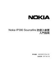
The Need for <strong>Provider</strong>-1/<strong>SiteManager</strong>-1Differentiating between levels of access permissions is critical not only for securing usertransactions, but also for monitoring for attacks, abuse and load management. Taskspecialization amongst administrators must also be supported so that security can becentralized.Service providers such as data centers and Managed Service <strong>Provider</strong>s (MSP), need tobe able to securely manage large-scale systems with many different customers and accesslocations. An MSP must potentially handle separate customer systems with manydifferent LANs, each with its own security policy needs. The MSP must be able toconfidentially address the security and management needs for each customer, each withtheir own system topology and system products. One policy is not sufficient for theneeds of so many different types of customers.A Data Center provides data storage services to customers, and must handle access andstorage security for many different customers, whose requirements for private andsecure access to their data are of critical importance.We will examine a few basic scenarios: the MSP, the Data Center, and the large scaleenterprise.Management Service <strong>Provider</strong>s (MSP)An MSP manages IT services, such as security and accessibility, for other companies,saving these companies the cost of an expert internal IT staff. A management systemmust accommodate the MSP’s own business needs, deploying an IT managementarchitecture that scales to support a rapidly growing customer base, while minimizingsupport procedures and dedicated hardware.The MSP handles many different customer systems, which creates a variety of ITmanagement needs. Home users may require basic internet services, with securitymanaged by VPN-1 Edge/Embedded appliances. Small companies may require internetand customized-security coverage; others want autonomy to manage their own securitypolicies. One small company wants to protect its computers with a single enforcementpoint, a FireWall-1 gateway, while another requires gateways and security services forseveral offices and multiple networks which must communicate securely and privately.While the MSP must have administrators that can manage the entire MSP environment,individual customer’s administrators cannot have access to other customers'environments.Let’s examine the network of a fictitious MSP, SupportMSP:10
FIGURE 1-1Example of an MSP environmentService providers need a management tool designed to specifically address the uniquechallenges of large-scale private-customer management. These different andunconnected customers’ systems must be centrally managed, yet the MSP must alsomaintain the privacy and integrity of each customer’s system.Further, the MSP must be able to flexibly manage security policies. Customers cannotall be assigned one security policy. It may be that specialized security policies suit a setof clients with similar needs (for example, supermarkets with many branches), whereasindividualized policies better suit other customers (such as independent tax accountantsand dentists). Repetitive policy changes and time-intensive end-user management are acommon problem if policies cannot be managed adroitly.The MSP must also handle communication and activity logging for networktroubleshooting and reporting purposes. Comprehensive logging for many differentcustomers and disparate systems can be process- and space intensive, draining systemresources if not handled carefully. This creates both administration issues and uniquesecurity policy requirements.Chapter 1 Introduction 11
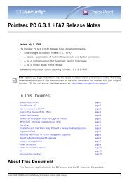
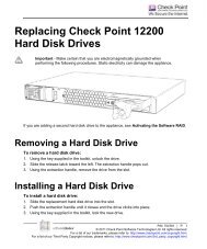
The Need for <strong>Provider</strong>-1/<strong>SiteManager</strong>-1Data CentersThe data service provider is a type of service center, a company that provides computerdata storage and related services, such as backup and archiving, for other companies.For example, let’s examine the network of a fictitious Data Center:FIGURE 1-2Example of a Data CenterSimilar to the MSP, the Data Center manages its own environment, whereas individualcustomer administrators and customers cannot have access to other customers'environments.Large EnterprisesBusinesses that expand through lateral and horizontal integration, such as conglomeratesor holding companies, face security policy challenges due to the diverse nature of theirsubsidiaries’ businesses. In these complex environments, security managers need theright tools to manage multiple policies efficiently. Central management of securitypolicy changes, which are enforced by the different firewalls throughout the system,ensure that the entire corporate IT architecture is adequately protected.Let’s look at a sample deployment for an automotive manufacturing concern:12
FIGURE 1-3Conglomerate’s networkCorporate IT departments must manage security services for a wide-spread system,with link-ups with vendors, external inventory systems, billing inputs, and reportingrequirements. Different branches are geographically distributed and have independentnetwork management. Yet the network security personnel must support acorporate-wide security policy, with rules enforcing access for appropriate users,preventing attacks, enabling secure communication and fail-over capabilities.IT departments must often delegate levels of authority among administrators, so thatthere is a hierarchy of access even within systems support. Whereas some administratorswill have global authorities to maintain the system backbone, others may handlespecialized activities and only require permissions for certain parts of the system. Forexample, an IT support person in a manufacturing branch would not necessarily needto have total administrator privileges for the logistics headquarters network, and avendor administrator that handles network maintenance would not need corporatewidepermissions.Chapter 1 Introduction 13
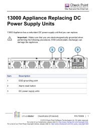
The <strong>Check</strong> <strong>Point</strong> SolutionIT services in large scale enterprises must often log network activity for securitytracking purposes. Comprehensive logging can consume considerable system resourcesand slow down a corporate network, if not deployed with an appropriate solution. Forenterprises with local and remote branches, centralized failover security management isanother critical success factor in achieving efficient and comprehensive system security.For Big Bank, different types of permissions and access management are required toprotect internal networks and separate them from external networks accessible to users.FIGURE 1-4Big Bank’s networkThe <strong>Check</strong> <strong>Point</strong> Solution<strong>Check</strong> <strong>Point</strong>’s <strong>Provider</strong>-1/<strong>SiteManager</strong>-1 is the best-of-breed security managementsolution designed to meet the scalability requirements of service provider and largeenterprise Network Operating Center environments. A unique three-tier, multi-policymanagement architecture and a host of Network Operating Center oriented featuresautomate time-consuming repetitive tasks common in Network Operating Center14
Basic Elementsenvironments. <strong>Provider</strong>-1/<strong>SiteManager</strong>-1 meets the needs of both the enterprise and ofservice providers serving the enterprise market. This solution dramatically reduce theadministrative cost of managing large security deployments.The basic three-tier security architecture of the VPN-1 Pro system, consisting ofenforcement points, a management console, and a GUI, delivers a robust mechanism forcreating firewall security policies and automatically distributing them to multipleenforcement points. <strong>Provider</strong>-1/<strong>SiteManager</strong>-1 supports central management for manydistinct security policies simultaneously.Companies envision horizontal growth throughout an industry, to implementeconomies of scale through incorporation of partner-companies and vendors.Enterprises want to manage vertical growth through product differentiation. Securitymanagement achieves a new level of customization and flexibility with<strong>Provider</strong>-1/<strong>SiteManager</strong>-With <strong>Provider</strong>-1/<strong>SiteManager</strong>-1 security policies can be customized. Enterprises can,for example, tailor a security policy to enable vendor applications which tie intocorporate financial networks to communicate safely and securely, yet without havingaccess to confidential corporate data. Or a security policy can enable franchisecompanies to communicate with regional and international headquarters, yet safeguardthe franchise internal network integrity.An administrator can create policies for groups of customer firewalls, and/or createhigh-level global policies that manage all customer polices at once. The ability to setpolicy at every level, including both the customer and global level, delivers exceptionalscalability by eliminating the need to recreate policies and policy changes, potentially tothousands of devices.Basic ElementsThe <strong>Provider</strong>-1/<strong>SiteManager</strong>-1 system is designed to manage many widely distributedenforcement points, for networks that may belong to different customers, differentcompanies, or different corporate branches.The primary element of a security system is the enforcement point, the VPN-1 Progateway. Administrators decide how this firewall is to be managed and apply a securitypolicy, with rules that determine how communication is handled by the firewall.A Customer Management Add-On (CMA) is a virtual customer management. TheCMA manages Customer’s enforcement points, that is their firewalls. Through theCMA, an administrator creates policies for Customer gateways.Chapter 1 Introduction 15
The <strong>Check</strong> <strong>Point</strong> SolutionThe Multi-Domain Server (MDS) houses the CMAs, as well as all of the <strong>Provider</strong>-1system information. It contains the details of the <strong>Provider</strong>-1 network, its administrators,and high level customer management information.The MDS can hold a substantial amount of customer network and policy detail on asingle server, providing a powerful, centralized management node. Multiple MDSs canbe linked in the <strong>Provider</strong>-1 system to manage thousands of policies in a singleenvironment, and to provide fail-over capabilities.The CMA is the equivalent of a stand-alone SmartCenter Server in the VPN-1 Promodel (see the VPN-1 Guide and FireWall-1 and SmartDefense Guide). But unlike theSmartCenter Server, the CMA is a manager, located on the MDS. Although manyCMAs can be stored on the same MDS, CMAs are completely isolated from each other,providing absolute customer privacy. In a large enterprise, each CMA may managebranch or department firewalls, depending on the security resolution required by thecorporate security policy.CMAs are located inside the <strong>Provider</strong>-1/Site-Manager-1 environment. The VPN-1 ProModule can be located in a separate network, in a separate city or country.FIGURE 1-5Distributed Management Configuration16
Basic ElementsExample: MSP deploymentLet’s examine the basic system components at a less granular level, looking at a start-upMSP setup with <strong>Provider</strong>-1. The service provider, <strong>Provider</strong>, has an MDS and aninternal network, connected to the internet and protected by a VPN-1 Pro gateway.This service provider offers security services to two customers, and manages theirVPN-1 Pro gateways.Both customers have VPN-1 Pro gateways protecting internal corporate network.Typing.Com has one network with one firewall. TravelAgency has two branches, eachprotected by its own VPN-1 Pro gateway. Each customer has its own CMA, whichresides in the service provider’s MDS, inside the <strong>Provider</strong>-1 network environment.Each CMA can manage more than one VPN-1 Pro gateway. TravelAgency has its ownprivate CMA, that manages both of TravelAgency’s VPN-1 Pro gateways. Typing.Comalso has its own private CMA, which manages its VPN-1 Pro gateway. TravelAgencycannot access information about the Typing.Com environment, nor about the serviceprovider’s environment.Notice that <strong>Provider</strong> also has a CMA to manage its own firewall.FIGURE 1-6How CMAs manage VPN-1 Pro gatewaysChapter 1 Introduction 17
The <strong>Check</strong> <strong>Point</strong> SolutionExample: Enterprise deploymentWhereas a service provider manages individual customer networks, a large enterprisemanages branches and departments. So, let’s consider a <strong>Provider</strong>-1/<strong>SiteManager</strong>-1 setupfor an international accountancy firm. The firm has its corporate headquarters inLondon, with one branch office in Manchester, and another in Paris. Each of thebranches have VPN-1 Pro gateways protecting internal corporate networks. Let us saythat in this corporate environment, all security management is handled through thecorporate headquarters in London.How can this corporate system be protected? The branch offices are assigned CMAs tomanage their gateways. In this case, the IT department is centralized in the corporateheadquarters in London. An MDS has been created in London to manage the system.The Manchester corporate branch’s VPN-1 Pro gateway is handled by its own CMA.The Paris and Nice branches are both managed by another CMA. Although the MDSand the gateways themselves are in different cities and countries, management iscentralized and handled by the IT department in the London office.FIGURE 1-7Enterprise deployment18
<strong>Point</strong> of Presence (POP) Network EnvironmentMulti-Domain GUI<strong>Provider</strong>-1/<strong>SiteManager</strong>-1 administrators use the Multi-Domain GUI (MDG) as theprimary interface to handle customer security management. The MDG has many“views,” tailored to display information relevant to specific tasks.FIGURE 1-8MDG - Close-upThe MDG is the tool administrators use to manage the entire <strong>Provider</strong>-1 environment,and provides an easy way to incorporate Customers and their networks into the<strong>Provider</strong>-1/Site-Manager-1 system. It is also used to update customer and gatewayinformation; and to assign and navigate between global policies. Using the MDG,administrators can provision and monitor security through a single console, and overseerules, policies, logs, statuses, and alerts for hundreds of customers.<strong>Point</strong> of Presence (POP) Network EnvironmentSome small scale businesses may not want the expense of a network or IT maintenancestaff. MSPs can provide a total IT package for these customers, using the POP networksolution to provide secured, VPN-1 Pro protected internet service. In the standard<strong>Provider</strong>-1/<strong>SiteManager</strong>-1 configuration we have seen, all of the customer’s firewalls aredeployed on the customer’s premises. In a POP-based configuration, the firewalls aredeployed in the POP center on the service provider’s premises.Chapter 1 Introduction 19
The <strong>Check</strong> <strong>Point</strong> SolutionLeased lines to the POP service center provide secured Internet access for Customers.All <strong>Provider</strong>-1/<strong>SiteManager</strong>-1 components, such as the MDS and the MDG (theadministrative GUI), are located on the service provider’s premises. Customers dial-into receive services, and connect to the Internet via the POP center. Although theirusage is monitored and protected, they do not have to be involved in any of thesecurity management.All aspects of security and access are completely maintained by the MSP, using CMAson the MDS to manage the enforcement point in the POP center. The CMAs in theMDS do this by managing the security policies for the VPN-1 Pro gateways thatprotect customer access.FIGURE 1-9A simple model of a POP configurationFor some MSPs, using VPN-1 Pro VSX technology to provide customer firewalls is acost-saving solution. When setting up a POP site using VSX, individual securitydomains can be aggregated on a single platform, substantially minimizing hardwareinvestment. <strong>Provider</strong>-1/<strong>SiteManager</strong>-1 VSX has special features which enable CMAs tomanage the security policies for the VSX virtual firewalls, protecting customer sitesfrom intrusion. For more information, see the VSX Guide and the <strong>Provider</strong>-1 VSXGuide.20
Managers and ContainersFIGURE 1-10 POP center using VSXManagers and ContainersThere are two “types” of MDS: a Manager, which contains <strong>Provider</strong>-1 systeminformation, and a Container, which holds the CMAs. The Manager is the entry pointfor administrators into the <strong>Provider</strong>-1/<strong>SiteManager</strong>-1 environment, via the MDG, the<strong>Provider</strong>-1 GUI.A single MDS computer can hold a combined Manager/Container. Or they can resideseparately on different computers, where one MDS is a standalone Manager whereasanother is a standalone Container. There must be at least one Manager and oneContainer per <strong>Provider</strong>-1/<strong>SiteManager</strong>-1 system.In an environment where there are numerous Customers, it is advised to use severalContainers to “house” the CMAs. The CMAs located on the MDS container store andmanage the Customer’s Network Object database and Security Policies. They receivestatus notifications and real-time monitoring data from the customer's modules andreceive logs from customer's modules by default, unless the logging properties of someor all modules are configured differently. A Container with an overload of CMAs cansuffer performance-wise. Using Containers, multiple MDSs can cascade to managethousands of CMAs in a single environment.Multiple administrators can simultaneously access the system via the MDG byconnecting to the same, or different, MDS Managers. Administrators can access theentire <strong>Provider</strong>-1/<strong>SiteManager</strong>-1 system from each of the Managers, as complete systeminformation is stored on each Manager.Chapter 1 Introduction 21
The <strong>Check</strong> <strong>Point</strong> SolutionLet’s look at a <strong>Provider</strong>-1/Site-Manager-1 environment for a service provider thathandles numerous small customers, and several large-scale customers.FIGURE 1-11 Multiple MDSs in the service provider environmentThis service provider needs a robust system with many Containers to handle the largeamount of information stored for all of its customers. There are two MDS Managers inthis system. One is housed as a standalone Manager, whereas the other is housed with aContainer on the same server. There are also three Containers, which are managed bythe MDS Managers. Another computer runs the MDG, the <strong>Provider</strong>-1 graphicalmanagement tool. Administrators can login to any Manager, and see the entire systemvia the MDG.MDS SynchronizationManager synchronization (for <strong>Provider</strong>-1 system information) is performed at the MDSlevel. MDS Managers are “mirrors” of each other. If there is more than one MDSManager in the system, each Manager will contain all the information regarding the<strong>Provider</strong>-1/Site-Manager-1 management system such as administrator hierarchy,selected customer and network information.MDS Managers contain three databases: MDS, Global Policy and ICA. The MDSManager’s MDS database (general information) is synchronized whenever changes aremade. The Global Policy database is synchronized either at configurable intervalsand/or events, or it is synchronized manually. Interconnected, mutually redundant MDSManagers form a robust management system providing non-stop access, without theneed to deploy dedicated hardware or software redundancy.22
Log ManagersMDG management activities can be performed using any of the MDS Managers. MDSManager synchronization does not mirror CMA-specific data. For example, internaldomains and customer level policy rules are known only at the CMA level, so they arenot synced by MDS Managers. To enable CMA failover, you must set up CMA HighAvailability. CMA High Availability synchronization is separate from MDSsynchronization.For more information, see Chapter 10, “High Availability” and Chapter 5, “GlobalPolicy Management.”FIGURE 1-12 MDS Synchronization in an Enterprise networkLog ManagersMulti-Domain Log ModuleThe Multi-Domain Log Module (MLM) is an optional server that is dedicated to logcollection, separating critical management activities from logging traffic. It therebyenhances performance and provides the infrastructure for further data-mining activitiesand improves performance for large deployments by offloading log processing activitiesfrom the MDS. It is recommended for systems with many CMAs or a heavy loggingload.Redundant log infrastructures can be created by designating an MLM as a primary logserver and designating the MDS as a backup. In the event that the MLM cannot bereached, logs are redirected to the MDS. It is possible to have multiple MLMs in theChapter 1 Introduction 23
The <strong>Check</strong> <strong>Point</strong> Solution<strong>Provider</strong>-1/<strong>SiteManager</strong>-1 network. The MLM is controlled by the MDG, andmaintains Customer Log Modules (CLMs), with a separate log repository for eachCustomer.Let’s look at Big Bank. Big Bank is expanding and has opened a number of newbranches. It has decided to track activity in its system, to satisfy security requirements.It has created an environment with three MDS’s. The system administrators have set upan MDS Manager/Container with a second Container to manage VPN-1 Pro gatewaysthroughout the different bank branches. They have also set up an MLM, to trackactivity.FIGURE 1-13 A simple system with an internal MLMCustomer Log ModuleA Customer Log Module (CLM) is a log server for a single customer. Service providerscan deploy CLMs to monitor specific customer modules. Enterprises may deploy CLMsto monitor branch activity.In the example below, Big Bank uses a specific CLM to collect information about theParis branch’s gateway activities.24
High AvailabilityFIGURE 1-14 CLM gets activity data from customer’s VPN-1 Pro gatewayHigh AvailabilityCMA High AvailabilityCMA High Availability is implemented by using two CMAs to manage one customernetwork, one in active mode, the other in standby. Implementing management HighAvailability guarantees fail-over capability. At any given time, only one CMA is active,while the standby CMA is synchronized with the active CMA.Data synchronization between the two CMAs greatly improves fault tolerance andenables the administrator to seamlessly activate a standby CMA when required. WithHigh Availability, should a CMA fail for any reason, due to say a hardware failure, thestandby CMA can continue operation without service interruption.Chapter 1 Introduction 25
The Management ModelThe High Availability scheme requires one Primary CMA and one Secondary CMA,which are housed separately, on different MDS computers. Administrators make securitypolicy changes through the active CMA. If policy changes are made with the activeCMA, the standby CMA can be setup to synchronize automatically to reflect thesechanges.These CMAs must be synchronized in order to maintain the same information. It ispossible to configure the High Availability feature to synchronize automatically for eachpolicy installation operation, on each policy save operation and on any other scheduledevent. If the active CMA’s data has not be synchronized with the standby CMA, youcan still use the standby CMA, which is updated until the moment of the lastsynchronization.Security Policies in <strong>Provider</strong>-1Security Policies are created to enforce security rules. Administrators can create securitypolicies and rules tailored to a specific customer, or a type of customer. In the<strong>Provider</strong>-1/<strong>SiteManager</strong>-1 environment, administrators create Customer securitypolicies for a specific set of gateways, using the CMA, which is the equivalent of theSmartCenter Server in the VPN-1 Pro model. To find out details about how theVPN-1 Pro works with security policies, see the VPN-1 Guide and FireWall-1 andSmartDefense Guide.The need for Global PoliciesBesides security policies for a specific set of gateways, administrators need to createpolicies which apply to the entire <strong>Provider</strong>-1 environment. The separation betweendifferent levels of policies, and different types of policies, means that Customer-levelsecurity rules do not need to be reproduced throughout the entire <strong>Provider</strong>-1environment. Policies can be created and privately maintained for each customer,ensuring a customer’s security integrity. Global Policies enforce security for the entire<strong>Provider</strong>-1 system. This is described in greater detail in Chapter 5, “Global PolicyManagement.”The Management ModelIn the <strong>Provider</strong>-1/<strong>SiteManager</strong>-1 environment, the management model has beendesigned so that network security managers can centrally and securely manage manydistributed systems. Network security is sharpened by differentiating between differentlevels of security needs, and differentiating between access privileges and needs. The<strong>Provider</strong>-1/<strong>SiteManager</strong>-1 management model allows you to designate trusted users26
Administrators(administrators) with different access rights. It enables trusted communication bothwithin the <strong>Provider</strong>-1/<strong>SiteManager</strong>-1 network, and with customers’ networkenvironments.AdministratorsIt is important, for security purposes, that there be different types of administrativeauthority. Administrators with authority over the entire system are needed in order tomanage the entire <strong>Provider</strong>-1/<strong>SiteManager</strong>-1 system. But there also must be a level ofadministration authority which only applies to the customer environment and not tothe <strong>Provider</strong>-1/<strong>SiteManager</strong>-1 system.It is not appropriate for an administrator who remotely manages a VPN-1 Pro gatewayin a particular customer network, to be able to have authority over the entire<strong>Provider</strong>-1 system. This could be a serious security breach, as a customer’s internal staffwould have access to other customer networks. For an MSP which handles numerouscustomers, it would not be appropriate for a particular customer administrator who isnot familiar with the entire system to, say, have the authority to shut down an MDSManager and delete all the superusers from the system.In the <strong>Provider</strong>-1/<strong>SiteManager</strong>-1 environment, four types of administrators have beendesignated to handle different levels of responsibility. While there needs to beadministrators who have the authority to create and manage the entire<strong>Provider</strong>-1/<strong>SiteManager</strong>-1 environment, not every administrator in the system has thislevel of complete control.Chapter 1 Introduction 27
The Management ModelTABLE 1- 1Administrators levels and their access permissionsAdministrator<strong>Provider</strong>-1SuperuserCustomerSuperuserPermissions<strong>Provider</strong>-1 Superusers manage the entire <strong>Provider</strong>-1 system andcan oversee all the networks of all Customers in the<strong>Provider</strong>-1/<strong>SiteManager</strong>-1 system. They can use all MDG toolsrelating to Customer and MDS management and can manage allother administrators. <strong>Provider</strong>-1 Superusers have sole permissionto manage and change the MDSs. They can:• Add, edit or delete MDSs, including manager servers,containers, High-Availability servers, logging servers, etc.• Enable or disable a computer’s permission to access the MDG(GUI Clients).Customer Superusers can manage the networks of all Customersin the system, using the MDG and SmartConsole tools. They canuse all MDG tools relating to Customer management; create, editand delete Customers; and see all the network objects for all ofthe Customers. Customer Superusers can manage CustomerManagers and None Administrators. However, they cannotmanage or change the MDS environment or manage <strong>Provider</strong>-1Superusers.28
Management ToolsAdministratorCustomerManagerNonePermissionsCustomer Managers manage their assigned set of customers’networks from within the <strong>Provider</strong>-1 environment, but have fewerpermissions than Customer Superusers. They can:• Access the General, Global Policies, High Availability andConnected Administrators Views.• See and manage (add, edit and delete) their Customers’ networkobjects.If Customer Managers are assigned Read/Write/All permissions,they can:• Edit their Customers.• Add, edit and delete their Customer's CMAs and CLMs.• Start or stop their Customer's CMAs and CLMs.• Import their Customer’s CMAs to another MDS.•Create None administrators for their customers.None Administrators manage their Customers according to thepermissions they were assigned. They work outside of the<strong>Provider</strong>-1 management environment managing Customers’internal networks using the SmartConsole tools, such asSmartDashboard, SmartView Tracker and so on. They do not haveaccess to the <strong>Provider</strong>-1/<strong>SiteManager</strong>-1 system, and cannot openan MDG. They may be customer’s resident administrators.Management ToolsMulti-Domain GUIAdministrators use the Multi-Domain GUI (MDG), the interface through which<strong>Provider</strong>-1/Site-Manager-1 administrators handle customer security management. Thegeneral view is shown below:Chapter 1 Introduction 29
The Management ModelFIGURE 1-15MDG - The General ViewAdministrators use the MDG to manage the <strong>Provider</strong>-1/Site-Manager-1 environmentand monitor Customers’ networks. This tool provides an easy way to add Customersand their networks to the <strong>Provider</strong>-1/Site-Manager-1 management system.Administrators can create, update, change and delete customers, CMAs information;assign licenses; view and assign policy policies, which are stored centrally on the MDS.Through a single console, administrators can provision and monitor security, byassigning and overseeing rules, policies and logging setups, as well as monitoring logs,statuses, and alerts for hundreds of customers.The MDG also is used to create administrators of all four types and assign theirpermissions. The MDG can even be used to designate which other computers can beentrusted to run the MDG. Administrators can create a logging setup by adding anMLM (Log Containers) to the <strong>Provider</strong>-1/Site-Manager-1 management system, anddesignating a dedicated customer’s server as a CLM for that customer. Further, it ispossible to update <strong>Check</strong> <strong>Point</strong> software for any and all <strong>Provider</strong>-1/Site-Manager-1 andCustomer network computers using SmartUpdate, via the MDG.From the MDG, an administrator can launch Global SmartDashboard to create GlobalPolicies, or the administrator can launch SmartConsole Clients for each of theCustomers. Outside of the <strong>Provider</strong>-1/<strong>SiteManager</strong>-1 environment, local administratorscan also run SmartConsole Client applications for each of the Customers.30
Management ToolsSmartConsole Client ApplicationsSmartConsole Clients are the <strong>Check</strong> <strong>Point</strong> tools used to design, manage, monitor andlog the firewall enforcement policies. SmartConsole Clients include all the following:• SmartDashboard is used by the system administrator to define and manage theSecurity Policy. From this SmartConsole you can access many <strong>Check</strong> <strong>Point</strong> featuresand add-ons.• SmartView Tracker is used for managing and tracking logs throughout the system.• SmartView Status is used for managing, viewing alerts and testing the status ofvarious <strong>Check</strong> <strong>Point</strong> components throughout the system.• SmartUpdate is used to manage and maintain a license repository, as well as tofacilitate upgrading <strong>Check</strong> <strong>Point</strong> software.• SecureClient Packaging Tool is used to define user profiles forSecuRemote/SecureClient clients.• SmartView Monitor is used to monitor and generate reports on traffic on interfaces,<strong>Provider</strong>-1/<strong>SiteManager</strong>-1 and QoS modules, as well as on other <strong>Check</strong> <strong>Point</strong>System counters.• SmartView Reporter is used to generate reports for different aspects of networkactivity.• User Monitor is used for managing SecuRemote users.• SmartLSM is used for managing large numbers of ROBO Gateways via theSmartCenter Server or <strong>Provider</strong>-1 CMA.Sample Deployment - Administrator SetupsLet’s examine a sample deployment, in which a service provider has an MDG consoleset up within the <strong>Provider</strong>-1/<strong>SiteManager</strong>-1 environment, and customers have theirown consoles within their internal networks.The service provider’s <strong>Provider</strong>-1 Superuser administrator, Rosa, uses the installationCD and command line utilities to configure and set up the entire<strong>Provider</strong>-1/<strong>SiteManager</strong>-1 environment. Then, she uses the MDG and the GlobalSmartDashboard to manage the global policies. As a <strong>Provider</strong>-1 Superuser, Rosa isresponsible for everything to do with the physical layout of the service provider’senvironment, and managing all the highest level security authorizations.Chapter 1 Introduction 31
The Management ModelFIGURE 1-16 Rosa sets up the <strong>Provider</strong>-1 environmentRosa knows that her <strong>Provider</strong>-1 environment will run a large system, with hundreds oreven tens of thousands of customers, and it will not be possible for one administrator tohandle all the activity. It is time to start considering staffing issues. Customer Superuserscan handle all Customer specific management activities. They can create/delete/editCustomers and create edit or delete CMAs. Rosa authorizes Martin to be a CustomerSuperuser. Now Martin can add customers to the system.FIGURE 1-17 Martin adds customers to the <strong>Provider</strong>-1 environmentMartin starts adding customers into the system. Each customer needs a security policyto monitor the customer network’s enforcement point, the VPN-1 Pro gateway. Thework is really piling up! Now that the customer base is expanding, it is time for Martin,as a Customer Superuser, to add more customer administrators.Martin authorizes Tony to be a Customer Manager for the customers Accountant andPharmacy2Go. Customer Managers can handle many Customer specific managementactivities. They can add, edit or delete their Customer’s CMAs. They can start or stop32
Management Toolstheir Customer's CMAs and CLMs. They can also import their Customer’s CMAs toanother server, and create customer security rules. It’s time for Tony to create securitypolicies for Pharmacy2Go and for Accountant.FIGURE 1-18 Tony creates security rules for customersThe company Pharmacy2Go has a resident IT manager, Sandrine, who handles localnetwork maintenance and security. Tony works with Sandrine to ensure thatPharmacy2Go’s network is running securely and safely.As a Customer Manager, Tony can authorize None administrators, who are outside ofthe <strong>Provider</strong>-1/<strong>SiteManager</strong>-1 management environment, but may administer thecustomer VPN-1 Pro gateways themselves. Tony adds Sandrine to the list ofadministrators as a None administrator, so that she can use SmartConsole applications tomonitor and track activity in Pharmacy2Go’s network.Chapter 1 Introduction 33
The <strong>Provider</strong>-1/<strong>SiteManager</strong>-1 Trust modelFIGURE 1-19 Sandrine works with SmartConsole ClientsSandrine can run SmartConsole Client applications for Pharmacy2Go’s network, nowthat she has made a None administrator. Remember, None administrators manage theirown internal networks via the CMA. They do not have access to other elements in the<strong>Provider</strong>-1/<strong>SiteManager</strong>-1 environment.Notice that the <strong>Provider</strong>-1 network itself needs to maintain its own security, protectingthe confidentially of critical information regarding customer networks, administrators,and access details, as well as for its own network! It can use a stand-alone VPN-1 Progateway, or define a CMA to manage its gateway. If the gateway is standalone, Rosa canmanage it through its own SmartCenter Server. If maintained by the MDS, it ismanaged with a CMA.The <strong>Provider</strong>-1/<strong>SiteManager</strong>-1 Trust modelThe <strong>Provider</strong>-1/<strong>SiteManager</strong>-1 system provides a method for MDSs and CMAs toestablish secure, trusted and private communication between <strong>Check</strong> <strong>Point</strong> moduleswhile ensuring data integrity. This is a critical component in ensuring that systemmanagement commands and system information are delivered securely.34
Management Tools<strong>Provider</strong>-1/<strong>SiteManager</strong>-1 systems must establish safe process communication betweenMDSs, between MDSs and CMAs, between CMAs and the Customers’ Modules thatthey are managing, and between administrators and CMAs. To ensure secure andprivate communication, Secure Internal Communication is used.Secure Internal Communication (SIC)Secure Internal Communication (SIC) is used to establish trust between each of thecomputers and components in the <strong>Provider</strong>-1/<strong>SiteManager</strong>-1 system that mustcommunicate with each other. A basic explanation of how SIC works appears in theSmartCenter Guide.Safe communication ensures that the system can receive all the necessary information itneeds to run correctly. Although information must be allowed to pass freely, it also hasto pass securely. This means that all communication must be encrypted so that an impostercannot send, receive or intercept communication meant for someone else, beauthenticated, so there can be no doubt as to the identity of the communicating peers,and have data integrity, not have been altered or distorted in any way. Of course, it ishelpful if it is also user-friendly.The SIC model incorporates PKI. Certificates are issued to trusted communicatingparties by an Internal Certificate Authority. These certificates are then used toauthenticate every communication established between the communicating parties.The following security measures are taken to ensure the safety of SIC:• Certificates for authentication.• Standards-based SSL for the creation of the secure channel.• 3DES for encryption.Trust between a CMA and its customer networkIn order to ensure communication authentication between the <strong>Provider</strong>-1 environmentand the customer network environment, each CMA also has its own Internal CertificateAuthority (ICA), that is responsible for issuing certificates to the CMA’s Customergateways. The CMA ICA is part of the CMA data residing in the MDS Container.Each CMA ICA is associated with a specific Customer. A Customer’s secondary CMAshares the same Internal Certificate Authority as the primary CMA.The CMA’s ICA issues a certificate to each of the customer network VPN-1 Progateways. SIC can then be established between the CMA and each of its customer’sVPN-1 Pro gateways.Chapter 1 Introduction 35
The <strong>Provider</strong>-1/<strong>SiteManager</strong>-1 Trust modelDifferent CMAs have different ICAs to ensure that a CMA establishes securecommunication with its own customer’s gateways, but that different customer CMAscannot penetrate each other’s internal networks and establish communication withanother customer’s gateways.FIGURE 1-20 SIC between CMA and Customer gatewayTrust between a CLM and its customer networkThe CLM (Customer Log Manager) also receives a certificate from the CMA’s ICA.This is so that the Customer’s VPN-1 Pro gateways can establish communication withthe CLM, for tracking and logging purposes. The gateways and CLM must be able totrust their communication with each other, but only if they belong to the samecustomer. Otherwise, different customers could monitor each other, which would be asecurity breach.36
Management ToolsMDS communication with CMAsEvery MDS Container communicates with the CMAs that it houses locally and securelythrough a protocol called SIC local. This type of authentication, SIC local, is managedby the <strong>Provider</strong>-1/SiteManger-1 environment and allows internal MDS communicationto be trusted.SIC is used for remote (not on the same host) communication, whereas SIC local isused for a host’s internal communication. SIC local communication does not make useof certificates.Trust between MDS to MDSThe primary MDS Manager, the first Manager created, has its own Internal CertificateAuthority. This ICA issues certificates to all other MDSs, so that trustedcommunication can be authenticated and secure between MDSs. All MDSs share oneInternal Certificate Authority.FIGURE 1-21 SIC between MDSsThe ICA creates certificates for all other MDSs, and for <strong>Provider</strong>-1/<strong>SiteManager</strong>-1administrators. Administrators also need to establish trusted communication with theMDSs.Authenticating the administratorAdministrators are authenticated to access the MDS via the MDG either by using a UserName and Password combination (which is considered only semi-secure) or by using acertificate issued by the MDS ICA (far more secure).Chapter 1 Introduction 37
The <strong>Provider</strong>-1/<strong>SiteManager</strong>-1 Trust modelFIGURE 1-22 SIC between Administrator and MDSFor management purposes, administrators use the certificates provided by the MDSICA to establish trusted communication to manage the CMAs. This is because everyCMA also trusts the MDS ICA for administrator management activities using acommunication medium, CPMI. This means that administrators do not need to havecertificates issued to them for every CMA that they communicate with.FIGURE 1-23 SIC between administrators and a customer CMACPMIEach CMA is a CPMI (<strong>Check</strong><strong>Point</strong> Management Interface) server. The MDS is also aCPMI based server. The Multi-Domain GUI (MDG) communicates with the MDSserver over the CPMI protocol. Since CPMI is a generic open protocol and its clientside is included as part of the OPSEC SDK, third-party vendors can write clients toaccess the MDS. For more information on CPMI, see CPMI.pdf in the OPSEC SDKdocumentation.38
CHAPTER 2Planning the <strong>Provider</strong>-1EnvironmentIn This ChapterAsking yourself the right questions... page 40Consider the following scenario... page 42Protecting the <strong>Provider</strong>-1/<strong>SiteManager</strong>-1 network page 43MDS Managers and Containers in the <strong>Provider</strong>-1 Management Network page 44Setting up the <strong>Provider</strong>-1/<strong>SiteManager</strong>-1 Environment page 46Hardware Requirements and Recommendations page 51<strong>Provider</strong>-1/<strong>SiteManager</strong>-1 Order of Installation page 53Licensing and Deployment page 53Miscellaneous Issues page 63This Chapter deals with different aspects required in order to plan and prepare forsetting a first time deployment with <strong>Provider</strong>-1. In every first time setup there aregeneral questions that you need to ask yourself, such as• What do you need to know about the basic components that need to be installed?• How should the basic components be deployed and in what order should they beinstalled?• What are the hardware requirements that need to be considered?• What licenses need to be obtained in order to run the product?• What are other additional requirements that may influence the performance,strength or security of the environment?39
Asking yourself the right questions...In this chapter, we will deal with many of the questions that you need to considerwhen planning your <strong>Provider</strong>-1 environment.Asking yourself the right questions...There are many things that need to be considered when deciding how to deploy your<strong>Provider</strong>-1 environment, this section talks very generally about some of the issues.Specific details are discussed at a later stage.Safety comes firstWhatever deployment you choose to implement needs to safeguard and protect yournetworks. You will need to install an Enforcement module to protect <strong>Provider</strong>-1environment. For more information see, “Protecting the <strong>Provider</strong>-1/<strong>SiteManager</strong>-1network” on page 43MDS Managers & Containers - How Many Do You Need?Every <strong>Provider</strong>-1 management network requires at least one MDS Manager (where<strong>Provider</strong>-1 system information is stored and MDG clients can connect to it to monitorand control the <strong>Provider</strong>-1 system), and one MDS Container (where CMA/CLM data isstored per Customer.) and more important, The MDS Manager and MDS Containercan be installed together on one computer.Take note that the greater your Customer base the more Containers will be necessaryin the system to support the database load for these Customers. For more information,see “MDS Managers and Containers in the <strong>Provider</strong>-1 Management Network” on page44.Choosing The Right EnvironmentChoose the deployment that best suits your need, amongst the options you can deploya standalone or a distributed environment. For more information, see “Setting up the<strong>Provider</strong>-1/<strong>SiteManager</strong>-1 Environment” on page 46.Choosing The Right Platform• When choosing between a Linux, Solaris or <strong>Check</strong> <strong>Point</strong> SecurePlatformOperating System/platform, remember that all the MDSs in the system must all beof the same platform.• The <strong>Provider</strong>-1/ <strong>SiteManager</strong>-1 administrative tool, MDG, can run in bothWindows and Solaris environments.High AvailabilityIf you are supporting many complex Customer networks, you may decide to implementfailover/ recovery capabilities:40
• For CMA High Availability, you need to have at least two Containers. By creatingtwo containers, you will be able to create two CMAs for each Customer. TheCMAs will serve as Active and Standby Management servers for the Customer'sEnforcement points.• For MDS High Availability, where there is multiple entry points to the system, youshould also have at least two Managers in order to allow you to connect to thesystem with the MDG even when one of the Managers is not available.Logging & TrackingIf you decide to implement logging for tracking and troubleshooting purposes, for avery large system where many different services and activities are being tracked, it isrecommended that you have one or more dedicated log servers (MLM).Migrating In A Standalone EnvironmentIf you want to migrate standalone SmartCenter Server management components into<strong>Provider</strong>-1 CMAs, ensure that you are thoroughly acquainted with the procedure.Before you begin consult the Upgrade Guide and choose a method, and ensure a setupthat supports your migration strategy.Routing Issues In A Distributed EnvironmentIf you have a distributed system, with MDS servers located remotely, ensure that youhave considered routing issues. Routing must enable all MDS components of the<strong>Provider</strong>-1/<strong>SiteManager</strong>-1 system to communicate with each other, and for CMAs tocommunicate with customer networks. For more information, see “IP Allocation &Routing” on page 63.Platform & Performance Issues<strong>Check</strong> <strong>Provider</strong>-1/<strong>SiteManager</strong>-1 system hardware and platform requirements, andensure that you have the needed platform patches installed. If you have an MDS withmultiple interfaces, ensure that the total load for each MDS computer conforms toperformance load recommendations. For more information see, “HardwareRequirements and Recommendations” on page 51.Setting Up AdministratorsConsider which computers administrators will manage the system, and theadministration hierarchy that you want to establish.Setting Up LicensesOnce you have determined what sort of server/computer configuration you need, youwill want to ensure that you have the appropriate licenses. For more information, see“Licensing and Deployment” on page 53.Chapter 2 Planning the <strong>Provider</strong>-1 Environment 41
Consider the following scenario...Consider the following scenario...The following scenario outlines a typical example of the basic components and featuresthat can be implemented that need to be taken into consideration when planning.Environment: Distributed with High AvailabilityConsider the following: a medical supplies firm has several branch locations, andrequires failover capabilities. MDSs are installed in three branches: Kansas, Osaka, andMontenegro. Each MDS has a mix of primary and secondary CMAs.Security: VPN-1 Pro moduleCritical to comprehensive security, each MDS is protected by a VPN-1 Pro module.This Enforcement module should be managed by a CMA or by a standaloneSmartCenter Server.The gateway on which the Enforcement module is installed must have a security policythat adequately protects the network and which allows secure communication between<strong>Provider</strong>-1/<strong>SiteManager</strong>-1 components and external customer networks.The Enforcement module must have security rules that allow CMAs to communicatewith customer gateways, and that allow external customer administrators to accessCMAs.FIGURE 2-1CMA High Availability in an Enterprise networkRequirement: Logging an TrackingMost enterprise systems and MSPs require event logging and tracking. Accountabilityrequirements can lead to sizeable log maintenance. By default, logs will be stored on theCustomer’s CMA that manages the module which is generating the logs in the<strong>Provider</strong>-1 management network. For most systems, in terms of licensing, it is more42
cost-effective to dedicate an MLM server to store logs rather than purchase extraManagers for this purpose. It is recommended that you implement one or morededicated log servers (MLMs), depending on the activity tracking load in the system<strong>Provider</strong>-1 manages.For more information about logging, see Chapter 7, “Logging in <strong>Provider</strong>-1.”Requirement: GUI Clients & their PlatformsFinally, consider the platforms that will be used to run the GUI tools used to managethe <strong>Provider</strong>-1 and customer environments. The <strong>Provider</strong>-1 system is monitored usingthe MDG and SmartConsole Client applications. GUI Clients should be deployedeither inside or outside of the <strong>Provider</strong>-1 network to enable administrators to access the<strong>Provider</strong>-1/<strong>SiteManager</strong>-1 system. The MDG runs on either Solaris and Windowsplatforms; the platform does not have to match the MDS’s platform.Requirement: Routing & CommunicationIf GUI Clients are located outside of the <strong>Provider</strong>-1/<strong>SiteManager</strong>-1 network,communication between these computers and the MDS Manager(s) must be allowed. IfMDSs are in different remote locations, and there is more than one <strong>Provider</strong>-1network, communication between the remote MDSs and the local MDSs must beallowed. Also ensure appropriate routing to support communication between computersand servers.Protecting the <strong>Provider</strong>-1/<strong>SiteManager</strong>-1 networkNo matter how <strong>Provider</strong>-1 management networks are setup and deployed, eachmanagement network must be protected. Each network must have firewall protectionand an Enforcement module must be setup for this purpose. This Enforcement moduleshould be managed by a CMA or by a standalone SmartCenter Server.The gateway on which the Enforcement module is installed must have a security policythat adequately protects the network and which allows secure communication between<strong>Provider</strong>-1/<strong>SiteManager</strong>-1 components and external customer networks.This Enforcement module must ensure continued open communication between all thecomponents, enabling MDSs to communicate with each other, and management servers(CMAs, CLMs, CMA-HAs) to communicate with customer networks. It must supportproper routing. At the same time while the lines of communication must be open andfree, they must also be secure.The Enforcement module must have security rules that allow CMAs to communicatewith customer gateways, and that allow external customer administrators to accessCMAs.Chapter 2 Planning the <strong>Provider</strong>-1 Environment 43
MDS Managers and Containers in the <strong>Provider</strong>-1 Management NetworkMDS Managers and Containers in the <strong>Provider</strong>-1Management NetworkEvery <strong>Provider</strong>-1 environment requires at least one MDS Manager and one MDSContainer. Beyond the minimum requirements, to determine how many MDSs yourenvironment requires, consider the functionality of the different types of MDSs.In This SectionMDS ManagersUse the MDG to connect to the MDS Managers in order to monitor and control the<strong>Provider</strong>-1/<strong>SiteManager</strong>-1 environment. If more than one MDS Manager is deployed:• They can provide mutually redundant fail-over capabilities.• They can be configured to synchronize global policy data either automatically ormanually.MDS ContainersMDS Managers page 44MDS Containers page 44Choosing your deployment for MDS Managers and Containers page 45MDS Clock Synchronization page 46MDS Containers contain and manage Customer data such as the Customer’s networkobjects’ database and security policies, This data is private (per Customer) and thereforeit is not shared. Consider the following:• “MDS Containers and High Availability” on page 44• “MDS Containers and Performance Issues” on page 45MDS Containers and High AvailabilityCustomer data can only be maintained in a redundancy scenario, that is, if HighAvailability has been enabled for the Customer. This is called CMA-High Availability,or CMA-HA. Data sharing is on a Customer by Customer basis, and is synchronizedbetween the CMA and CMA-HA. At least two Containers are required for CMA HighAvailability because the Customer’s CMA-HA must be set up on a different Containerthan the CMA (see Chapter 10, “High Availability”). The Customer's Primary CMAshould reside on one Container and the Secondary CMA should reside on the other.44
Choosing your deployment for MDS Managers and ContainersMDS Containers and Performance IssuesThe Container load depends on the complexity of the Customer’s policies and setups.Multiple Containers can cascade to manage thousands of CMAs in a singleenvironment. In general, to support numerous Customers who have complex networks,it is advisable to deploy several Containers, since, a Container with an overload ofCMAs can suffer performance-wise.Choosing your deployment for MDS Managers and ContainersYou can set up your MDS Managers and Containers in Mirror Sites, or in a DistributedEnvironment.Setting up MDS Managers and Containers in Mirror SitesService provider usually need a robust system with many Containers to handle the largeamount of data and rules used to manage their customers’ networks. An MSP mayimplement a remote mirror site for disaster recovery. For example, an MSP can create a<strong>Provider</strong>-1 management network containing a Manager, with several Containershousing Customers’ CMAs. The MSP can also maintain a mirror site in another city,comprising of a secondary Manager, with several Containers storing CMA-HAs.MDS Managers and Containers in a Distributed EnvironmentAn enterprise system can centralize the <strong>Provider</strong>-1 management network at one branchyet have one or more backup MDSs at other locations. (For more information aboutfail-over options, see Chapter 10, “High Availability.”)For example, a corporate bank with several international branches locates the “primary”<strong>Provider</strong>-1 management network in their headquarters. But, to support active CMAsfor the different local branches, they maintain an MDS Container per region, at acentral regional branch. The CMA-HAs can be maintained for fail-over capabilities inthe <strong>Provider</strong>-1 management network MDSs in the headquarters, or distributed to thelocal MDS Containers. If a central regional branch contains an MDS Manager as well,the whole MDS environment can be accessed by connecting the MDG GUI client tothat server.Chapter 2 Planning the <strong>Provider</strong>-1 Environment 45
Setting up the <strong>Provider</strong>-1/<strong>SiteManager</strong>-1 EnvironmentFIGURE 2-2CMA High Availability in an Enterprise networkMDS Clock SynchronizationFor MDSs to be able to properly synchronize, all MDSs’ system clocks must besynchronized. If there is more than one MDS computer in the system, before installingany new MDS, first synchronize the computer clock with other MDSs in the system.The time of modification is written using UTC (Coordinated Universal Time), used byMDSs’ system clocks. Synchronize MDS clocks using any synchronization utility. It isrecommended that you reset regularly to compensate for clock drift. Correct databaseoperation requires that the MDS clocks are synchronized to the second. It isrecommended that MDS clocks be synchronized automatically at least once a day.Setting up the <strong>Provider</strong>-1/<strong>SiteManager</strong>-1 EnvironmentThe <strong>Provider</strong>-1/<strong>SiteManager</strong>-1 topology depends on system and business requirements.A number of simplified basic scenarios for enterprises are discussed in this section.<strong>Provider</strong>-1/<strong>SiteManager</strong>-1 is designed to flexibly support many different types ofmanagement network and customer network configurations. These include:• “A Typical Scenario” on page 47• “A Standalone <strong>Provider</strong>-1 Network” on page 48• “A Distributed <strong>Provider</strong>-1 Network” on page 49• “<strong>Provider</strong>-1 Network with <strong>Point</strong> of Presence (POP) center” on page 5046
A Typical ScenarioA Typical ScenarioEnterprises usually choose to put the <strong>Provider</strong>-1/<strong>SiteManager</strong>-1 management networkin its own segment, separated from the main enterprise network by an Enforcementmodule.FIGURE 2-3Separate and protect network segments<strong>Provider</strong>-1/<strong>SiteManager</strong>-1 servers are often separated from support servers such asRadius, LDAP, and anti-virus servers. This is not by any means a requirement.Chapter 2 Planning the <strong>Provider</strong>-1 Environment 47
Setting up the <strong>Provider</strong>-1/<strong>SiteManager</strong>-1 EnvironmentFIGURE 2-4Separate support segmentsA Standalone <strong>Provider</strong>-1 NetworkThe <strong>Provider</strong>-1/<strong>SiteManager</strong>-1 management system can be set up in one networklocation, with all the MDSs located in the same local network. Fail-over capabilities areenabled by having at least two Manager/Container MDSs. Management andmaintenance is centralized through the <strong>Provider</strong>-1/<strong>SiteManager</strong>-1 network segment.The advantage of this setup is that routing complexity is considerably reduced.Logs can be stored centrally on the MLM server (per Customer in different CLMs) andaccessed via SmartView Tracker.48
A Distributed <strong>Provider</strong>-1 NetworkFIGURE 2-5Separate <strong>Provider</strong>-1 segment with remote LoggingA Distributed <strong>Provider</strong>-1 NetworkThe <strong>Provider</strong>-1/<strong>SiteManager</strong>-1 management system can be set up in a local networklocation which containing MDSs. Additional a remote location can be setup whichcontains logging and disaster recovery capabilities, in the form of an MLM and fail-overMDS Manager/Containers. Routing must ensure that local and remote MDSs cancommunicate with each other to maintain MDS synchronization. Each<strong>Provider</strong>-1/<strong>SiteManager</strong>-1 network segment must have adequate protection, by aVPN-1 Pro Enforcement module.Chapter 2 Planning the <strong>Provider</strong>-1 Environment 49
Setting up the <strong>Provider</strong>-1/<strong>SiteManager</strong>-1 EnvironmentFIGURE 2-6Separate <strong>Provider</strong>-1 segments for disaster recovery/logging<strong>Provider</strong>-1 Network with <strong>Point</strong> of Presence (POP) center<strong>Provider</strong>-1/<strong>SiteManager</strong>-1 can be configured to manage a POP center which allowsbranch offices to receive service and secured Internet access via leased lines to the POPservice center. All <strong>Provider</strong>-1/<strong>SiteManager</strong>-1 components, such as the MDS and theMDG (the administrative GUI), are located in one network locations. Customers orcorporate users dial-in to receive services, and connect to the Internet via the POPcenter.Usage is monitored and protected via the <strong>Provider</strong>-1/<strong>SiteManager</strong>-1 managementnetwork, and branches do not have to be involved in any of the security management.All aspects of security and access are completely maintained using CMAs on the MDSto manage the enforcement point in the POP center. The CMAs in the MDS do thisby managing the security policies for the VPN-1 Pro gateways in the POP center.50
Disk SpaceFIGURE 2-7A simple model of a POP configurationHardware Requirements and RecommendationsWhen planning for your <strong>Provider</strong>-1 environment, you should take the followinghardware requirements of disk space and memory into consideration:Disk SpaceWhen considering disk space it is recommended to use volume management software.• MDS - Basic MDS functionality requires 100 MB.• CMA - The absolute minimum disk space required per CMA is 20 M. It isrecommended that swap space is twice that of physical memory.The <strong>Provider</strong>-1/<strong>SiteManager</strong>-1 disk space requirements for installation are as follows:• For basic MDS installation: 150MB.• For each CMA: 10MB for the CMA directory, 60 MB for swap.Chapter 2 Planning the <strong>Provider</strong>-1 Environment 51
Hardware Requirements and RecommendationsMemoryAs a CMA database expands to include more and more objects and Rules, it requires anincreasing amount of memory and swap space. The details below apply to a sampleCMA profile with:• 100 Network Objects• 40 Rules• 4 gateways.The CMA memory requirements vary depending on the CMA profile, i.e. theconditions under which it operates, the number of customer gateways, the complexityof the customer network, the size of the security policy rule bases, etc.TABLE 2-1CMA Memory RequirementsCMAProfileCMA LogCollectionCMA SmartDashboardOperationsSmartViewTrackerMemoryRequired1 15 logs per secondper CMAEvery 3rd CMA has an openSmartDashboard whichperforms edit and installoperationsEvery 3rd CMAhas an openSmartViewTracker20 MB2 15 logs per secondper CMASame No 13 MB3 No Same No 10 MBThe CMA memory requirement is not measured by the sum of the resident memoryused by the CMA processes. Some of the resident memory used is actually sharedamong CMAs (such as dynamic library code). When more CMAs are added to asystem, the system uses more swap space, reducing the resident memory used by eachCMA.The system is designed to operate under such conditions and deliver high qualityservice. Memory requirement measurements per CMA were done by testing how manyCMAs with the above profiles can actually be hosted on a MDS with a specific amountof memory, while maintaining a high grade of MDS service.The more CMAs, the more memory needed. Regarding processes, when the firstMDG is opened, a status collection mechanism is triggered to check CMA and gatewaystatuses. This process raises resource consumption. Concurrent MDG sessions share thesame information.In terms of RAM usage, the more processes, the slower the system.52
The Trial Period<strong>Provider</strong>-1/<strong>SiteManager</strong>-1 Order of InstallationFor each MDS component’s setup to be stable and workable it is important to conductsetup/installation in the following order:1 Install the Operating System (OS).2 Conduct OS hardening. It is advisable to remove unnecessary applications, scriptsor libraries that are not needed as they are not necessarily secure. It is advisable tolimit resident libraries and applications to those needed for system functionality.3 Install the OS patches.4 Install <strong>Check</strong> <strong>Point</strong> products.5 Install <strong>Check</strong> <strong>Point</strong> patches.6 Install <strong>Check</strong> <strong>Point</strong> hotfixes.The appropriate OS patches, and the <strong>Provider</strong>-1/<strong>SiteManager</strong>-1 installation procedureis discussed in Chapter 3, “Provisioning the <strong>Provider</strong>-1 Environment.”Licensing and DeploymentThe Trial PeriodAll purchased <strong>Check</strong> <strong>Point</strong> products have a 15 day trial period. During this period thesoftware is fully functional and all features are available without a license. After thatperiod, a permanent license must be installed in order to continue using the software.Alternatively, an evaluation license must be obtained.The starting point of this trial period is defined differently for different products. The<strong>Provider</strong>-1/<strong>SiteManager</strong>-1 trial period begins as soon as the MDS is installed (regardlessof its type). The trial license is for an MDS Manager maintaining up to 200 CMAs.Each CMA you create during the trial period receives its own trial license for a PrimaryCMA managing an unlimited number of gateways. The license supports the <strong>Check</strong><strong>Point</strong> SmartUpdate & SmartMap features and expires on the same day as the MDS’strial license.Considerations<strong>Provider</strong>-1/<strong>SiteManager</strong>-1 Components Installed at the NOCThe following components are deployed at the Network Operation Center:• Multi Domain GUIs (MDG)• Multi Domain Servers (MDS), including Multi Customer Log Modules (MLM)Chapter 2 Planning the <strong>Provider</strong>-1 Environment 53
Licensing and Deployment• Customer Management Add-on (CMA)• Customer Log Module (CLM)Selecting MDS and CMA licensesSimilar MDS components must be installed on different computers. Two Managerscannot share the same computer. Each Container must also be on a separate computer.However, a Manager/Container combination can be housed on the same computer.Licenses are available separately or combined for the MDS components.When considering which licenses to buy, a second MDS Manager is recommended fordisaster recovery. A standalone MDS Manager is available to be used for managementpurposes only, serving as an entry point to the system.If many CMAs will be supported by the system, or if the CMA load increases, moreMDS Containers are needed, not Managers. CMAs are maintained only on Containers.Licenses for MLMs (dedicated log servers) are inexpensive, so they are a cost effectivealternative to storing logs by default on Managers/Containers.The MDS license is per IP, and is based on the following factors:• The MDS type, whether Manager, Container, combined, or Log Manager (MLM).• For Containers, the MDS license depends on the number of CMA managed.<strong>Provider</strong>-1/<strong>SiteManager</strong>-1’s licensing is geared to match its scalable architecture.Licenses are matched to needs, and can be purchased to accommodate a growingCustomer base. Components are licensed according to the number of CMAs andVPN-1 Pro modules. New CMAs can be seamlessly integrated, by upgrading to a largerlicense.Each CMA requires its own CMA-level license. These are obtained per CMA’s IP. Theexceptions to this are the VSX Bundle license (see “VSX Bundle License” on page 60)and the MDS Pro license. In the MDS Pro license scheme, the license is per MDS andper MDS IP address. There is no need for special licenses per CMA IP address; it allowsthe user to purchase a block of CMA licenses without pre-specifying IPs. However, thelicense must then be “moved” to specific CMA IPs in order to be installed. The usercentre must be contacted in order to move the Pro license to CMAs appropriately.The MLM license is comprehensive so there is no need for separate licenses per CLM.A single license installed on the MLM applies to both the MLM and the CLMs itmaintains. CLMs are per customer and can receive logs from all of the Customer’smodules, regardless of their number. The number of modules that report to the sameMLM is unlimited.The MDG does not require a license.54
Further Licensing DetailManaging licenses<strong>Provider</strong>-1/<strong>SiteManager</strong>-1 uses SmartUpdate to incorporate newer versions andlicenses. A global licensing SmartUpdate View in the MDG provides for easy upgradefor required components and licenses.Licenses are additive. For example, an MDS Container license for 50 CMAs(CPPR-MDS-CONTAINER-50-NG) and an MDS Container license for 25 CMAs(CPPR-MDS-CONTAINER-25-NG) add up to 75 hosted CMAs.<strong>SiteManager</strong>-1The <strong>SiteManager</strong>-1 MDS is a low cost MDS, whose CMAs are limited to managingspecific modules. <strong>SiteManager</strong>-1 supports two license schemes:1 Backwards compatibility license scheme. In this license scheme, each <strong>SiteManager</strong>-1CMA manages only one module. The license is installed only at the MDS level: nolocal CMA licenses are required.2 Small Office module for 250 protected nodes. In this license scheme, each CMAcan manage only Small Office modules or modules protecting 250 hosts.Further Licensing DetailLicensing the Multi-Domain Server (MDS)There are two basic MDS components: Containers and Manager. Containers holdCMAs, whereas Managers manage the <strong>Provider</strong>-1/<strong>SiteManager</strong>-1 environment andprovide entry points for the MDG GUI Clients.TABLE 2-2 shows the license required for each MDS component.TABLE 2-2MDS Licensing SchemesLicenseCPPR-MDS-M-NGCPPR-MDS-C10-NGCPPR-MDS-C25-NGCPPR-MDS-C50-NGCPPR-MDS-C100-NGCPPR-MDS-C200-NGDescriptionManager component without CMAs (for login,Certificate Authority and MDS, Global Policy andCertificate data synchronization purposes only)Container hosting up to 10 CMAsContainer hosting up to 25 CMAsContainer hosting up to 50 CMAsContainer hosting up to 100 CMAsContainer hosting up to 200 CMAsChapter 2 Planning the <strong>Provider</strong>-1 Environment 55
Licensing and DeploymentTABLE 2-2MDS Licensing SchemesCPPR-MDS-MC10-NG Combined Manager and Container hosting up to 10CMAsCPPR-MDS-MC25-NG Combined Manager and Container hosting up to 25CMAsCPPR-MDS-MC50-NG Combined Manager and Container hosting up to 50CMAsCPPR-MDS-MC100-NG Combined Manager and Container hosting up to 100CMAsCPPR-MDS-MC200-NG Combined Manager and Container hosting up to 200CMAs<strong>SiteManager</strong>-1 LicensesThe <strong>SiteManager</strong>-1 MDS is a low cost MDS. <strong>SiteManager</strong>-1 supports two licenseschemes:1 Backwards compatibility license scheme: each <strong>SiteManager</strong>-1 CMA is limited tomanaging only one module. TABLE 2-3 shows the license required for each<strong>SiteManager</strong>-1 MDS component.TABLE 2-3<strong>SiteManager</strong>-1 — Backwards Compatibility Licensing SchemesLicenseCP-SM1-BASE100-NGCPSM-TR-B-10-CUSTBUNDLE-NGDescriptionFramework license for 100 CMAs. Mandatory license.Bundle license for 10 CMAs. Each of these licensesinstalled at the MDS level enables adding and runningup to 10 additional CMAs.56
Further Licensing Detail2 Small Office Module/250 protected nodes Module. TABLE 2-4 shows the licenserequired for the <strong>SiteManager</strong>-1 MDS and CMA components.TABLE 2-4<strong>SiteManager</strong>-1 — Small Office Licensing SchemeLicenseDescriptionCPSM-SMM-M-NG<strong>SiteManager</strong>-1 Manager without CMAs (forlogin, Certificate Authority and MDS, GlobalPolicy and Certificate data synchronizationpurposes only)CPSM-SMM-MC100-NG <strong>SiteManager</strong>-1 Combined Manager andContainer hosting up to 100 <strong>SiteManager</strong>-1CMAsCPSM-SMM-MC200-NG <strong>SiteManager</strong>-1 Combined Manager andContainer hosting up to 200 <strong>SiteManager</strong>-1CMAsCPSM-SMM-C100-NG <strong>SiteManager</strong>-1 Container hosting up to 100<strong>SiteManager</strong>-1 CMAsCPSM-SMM-C200-NG <strong>SiteManager</strong>-1 Container hosting up to 200<strong>SiteManager</strong>-1 CMAsCPSM-SO-CMA-1-NGFirst <strong>SiteManager</strong>-1 CMA managing oneSmall Office ModuleCPSM-ST-CMA-2-NGFirst <strong>SiteManager</strong>-1 CMA managing twoModules, each protecting up to 250 internalIPs.CPSM-SO-CMA-1-HA-NG Secondary <strong>SiteManager</strong>-1 CMA managing oneSmall Office ModuleCPSM-ST-CMA-2-HA-NG Secondary <strong>SiteManager</strong>-1 CMA managing twoModules, each protecting up to 250 internalIPs.Chapter 2 Planning the <strong>Provider</strong>-1 Environment 57
Licensing and DeploymentMulti-Customer Log Module (MLM) LicensesAn MLM is installed as a Container. In order to simplify the deployment process, asingle license installed on the MLM applies to both the MLM and the CLMs itmaintains. A customer’s CLM can receive logs from all of the customer’s modules,regardless of how many there are. See Chapter 7, “Logging in <strong>Provider</strong>-1,” for moredetails.TABLE 2-5MLM Licensing SchemesLicenseCPPR-MLM-C10-NGCPPR-MLM-C25-NGCPPR-MLM-C50-NGCPPR-MLM-C100-NGCPPR-MLM-C200-NGDescriptionMLM hosting up to 10 CLMsMLM hosting up to 25 CLMsMLM hosting up to 50 CLMs.MLM hosting up to 100 CLMs.MLM hosting up to 200 CLMs.Customer Management Add-on (CMA) LicensesThe CMA is a <strong>Check</strong> <strong>Point</strong> SmartCenter Server. Each CMA manages a singleCustomer’s network and requires a dedicated CMA license. While each CMA belongsto a single Customer, each Customer can have up to two CMAs, for High Availabilitypurposes. These two CMAs must be maintained on different MDSs.CMAs are licensed according to the number of modules they manage. There are fourlevels of CMA licenses to enable scalable, cost effective deployment:• CMA-1 — suitable for a Customer with one module.• CMA-2 — suitable for a Customer with up to two modules.• CMA-4 — suitable for a Customer with up to four modules.• CMA-U — suitable for a Customer with an unlimited number of modules.You do not have to install additional software when you create a CMA in the<strong>Provider</strong>-1 network. To add a new CMA, you only need add the CMA’s license, whichis ordered per CMA IP. The number of QoS enforcement modules managed by a CMAis unlimited and requires no special license.TABLE 2-6 shows the license required for each CMA componentTABLE 2-6CMA Licensing SchemesLicenseCPPR-CMA-1-NGCPPR-CMA-2-NGDescriptionFirst CMA, managing one Module.First CMA, managing up to two Modules.58
Further Licensing DetailTABLE 2-6CMA Licensing SchemesCPPR-CMA-4-NGCPPR-CMA-U-NGCPPR-CMA-1-HA-NGCPPR-CMA-2-HA-NGCPPR-CMA-4-HA-NGCPPR-CMA-U-HA-NGFirst CMA, managing up to four Modules.First CMA, managing an unlimited number of Modules.Mirror CMA, managing one Module.Mirror CMA, managing up to two Modules.Mirror CMA, managing up to four Modules.Mirror CMA, managing an unlimited number ofModules.The CMA manages any of the following:• VPN-1 Pro Modules versions 4.0, 4.1 and NG on a variety of platforms (Solaris,Linux, Nokia, AIX, HP, NT, Win2K)• Bay Networks DevicesCustomer Log Module (CLM) LicensesIf you want to host a CLM on a non-MLM MDS, you must install a CLM license.There is no limit to the number of CLMs that can be defined for a single <strong>Provider</strong>-1Customer (as opposed to the number of CMAs, which is limited to two); however,each CLM must be created on a separate MDS.TABLE 2-7CLM Licensing SchemeLicenseCPPR-CMA-CLM-NGDescriptionLicense for CLM hosted on non-MLM MDS.Module LicensesA Customer’s modules require licenses. Modules are licensed according to the numberof nodes at a site. A node is any computing device with an IP address connected to theprotected network. TABLE 2-8 lists the available module licenses.TABLE 2-8VPN-1 Pro Module Products and Licensing schemesLicenseCPFW-FM-25-NGCPFW-FM-50-NGDescriptionVPN-1 Pro Module protecting up to 25 internal nodes.VPN-1 Pro Module protecting up to 50 internal nodes.Chapter 2 Planning the <strong>Provider</strong>-1 Environment 59
Licensing and DeploymentTABLE 2-8VPN-1 Pro Module Products and Licensing schemesCPFW-FM-100-NGCPFW-FM-250-NGCPFW-FM-U-NGVPN-1 Pro Module protecting up to 100 internal nodes.VPN-1 Pro Module protecting up to 250 internal nodes.VPN-1 Pro Module protecting an unlimited number ofinternal nodes.<strong>Provider</strong>-1/<strong>SiteManager</strong>-1 also supports FloodGate-1, a QoS application. TABLE 2-9lists the available FloodGate-1 module products.TABLE 2-9FloodGate-1 Module Products and Licensing schemesLicenseDescriptionCPTC-FGM-25-NG FloodGate-1 Module managing QoS for up to 25internal nodes.CPTC-FGM-50-NG FloodGate-1 Module managing QoS for up to 50internal nodes.CPTC-FGM-100-NG FloodGate-1 Module managing QoS for up to 100internal nodes.CPTC-FGM-250-NG FloodGate-1 Module managing QoS for up to 250internal nodes.CPTC-FGM-U-NG FloodGate-1 Module managing QoS for an unlimitednumber of internal nodes.VSX Bundle LicenseThe VSX Bundle License provides licensing for managing VSs and CMAs, located onan MDS server. The bundle license is installed on the MDS server and permits aspecific number of VSs to be managed. The number of CMAs that can be defined onan MDS, equals the number of VSs permitted plus one. The additional CMA is used forthe CMA with VSX Box. The VSX bundle, however, does not limit the number ofVSXs or VRs.CMAs without a CMA-level license use the bundle license. If a CMA-level license isinstalled on a specific CMA to allow the management of a regular Gateway,(CPPR-CMA-10-NG, for example), then that CMA stops using the bundle license,and the VSs located on it are not counted off the bundle license. When a CMA ismanaging a non-VSX module, both a CMA-level license and container license on theMDS is required.60
Further Licensing DetailVSX Bundle License for HA CMAsThe VSX HA CMA Bundle License is used for HA CMAs on a primary or backupMDS for High Availability. CPPR-VSX-CMA-HA-10-NG for example, allowsdefining 10 VSs on HA CMAs. HA CMAs can use the regular bundle, but PrimaryCMAs cannot use the HA bundle.TABLE 2-10VSX Bundle License SchemesLicenseCPPR-VSX-CMA-10-NGCPPR-VSX-CMA-25-NGCPPR-VSX-CMA-50-NGCPPR-VSX-CMA-100-NGCPPR-VSX-CMA-250-NGCPPR-VSX-CMA-HA-10-NGCPPR-VSX-CMA-HA-25-NGCPPR-VSX-CMA-HA-50-NGCPPR-VSX-CMA-HA-100-NGCPPR-VSX-CMA-HA-250-NGDescriptionMDS hosting up to 10 CMAs plus one forthe CMA with VSX BoxMDS hosting up to 25 CMAs plus one forthe CMA with VSX BoxMDS hosting up to 50 CMAs plus one forthe CMA with VSX BoxMDS hosting up to 100 CMAs plus one forthe CMA with VSX BoxMDS hosting up to 250 CMAs plus one forthe CMA with VSX BoxMirror MDS hosting up to 10 CMAs plusone for the CMA with VSX BoxMirror MDS hosting up to 25 CMAs plusone for the CMA with VSX BoxMirror MDS hosting up to 50 CMAs plusone for the CMA with VSX BoxMirror MDS hosting up to 100 CMAs plusone for the CMA with VSX BoxMirror MDS hosting up to 250 CMAs plusone for the CMA with VSX BoxChapter 2 Planning the <strong>Provider</strong>-1 Environment 61
Licensing and DeploymentTABLE 2-11VSX-CMA Bundle License SchemesLicenseCPPR-VSX-CMA-C10-NGCPPR-VSX-CMA-C25-NGCPPR-VSX-CMA-C50-NGCPPR-VSX-CMA-C100-NGCPPR-VSX-CMA-C250-NGCPPR-VSX-CMA-HA-C10-NGCPPR-VSX-CMA-HA-C25-NGCPPR-VSX-CMA-HA-C50-NGCPPR-VSX-CMA-HA-C100-NGCPPR-VSX-CMA-HA-C250-NGDescriptionMDS bundle license for 10 Virtual Systemsand 11 CMAsMDS bundle license for 25 Virtual Systemsand 26 CMAsMDS bundle license for 50 Virtual Systemsand 51 CMAsMDS bundle license for 100 VirtualSystems and 101 CMAsMDS bundle license for 250 VirtualSystems and 251 CMAsMDS bundle license for 10 Virtual Systemslocated on Secondary CMAs and 11secondary CMAsMDS bundle license for 25 Virtual Systemslocated on Secondary CMAs and 26secondary CMAsMDS bundle license for 50 Virtual Systemslocated on Secondary CMAs and 51secondary CMAsMDS bundle license for 100 VirtualSystems located on Secondary CMAs and101 secondary CMAsMDS bundle license for 250 VirtualSystems located on Secondary CMAs and251 secondary CMAsLicense ViolationsWhen a license violation is detected, syslog messages are sent, pop-up alerts in theMDG, and audit entries in the SmartView Tracker stating the nature of the violation,are generated. In addition, an indication about the license violation appears on thestatus bar of the MDG.While the MDS is in violation, new CMAs, VSXs, VSs or VRs cannot be added to theMDS.62
IP Allocation & RoutingReplacing the Trial Period LicenseAfter the trial period expires, a permanent license must be installed. Before installing anew license, make sure the amount of CMAs and VSs do not exceed the amountpermitted by the new license. Installing a new license that allows less CMAs or VSsthan were configured during the trial period is a violation. As a result, the MDS willnot start.During the trial license, up to 200 CMAs and up to five VSs per CMA are permittedto be configured. In order to configure more than five VSs per CMA, a bundle licenseor CMA-level license would need to be installed. In order to successfully install abundle license before the trial license expires, the trial license must be disabled from theCMA. The command for disabling the trial period license on a CMA before the licenseexpires is:cpprod_util CPPROD_SetPnPDisable 1This command needs to be executed on each CMA separately and will only take effectafter restarting the CMA.The license violation mechanism is enforced separately for each MDS meaning that ifone MDS is in license violation, the other MDSs will continue to function.Installing the VSX Bundle LicenseInstalling the VSX Bundle license is similar to installing any other MDS level license.The installation can take place on the MDG from the MDS properties view or from thecommand line, using the “cplic put” command.Miscellaneous IssuesIn This SectionIP Allocation & Routing page 63Network Address Translation (NAT) page 64Enabling OPSEC page 66IP Allocation & Routing<strong>Provider</strong>-1/<strong>SiteManager</strong>-1 uses a single public IP interface address to implement manyprivate “virtual” addresses. The MDS Container uses virtual IPs to provide CMAs,CMA-HAs and CLMs, which reside on a Container, with IP addresses.Chapter 2 Planning the <strong>Provider</strong>-1 Environment 63
Miscellaneous IssuesEach MDS Container has an interface with an IP address, which is routable. Behind theinterface’s IP address the CMAs have a range of virtual IP addresses, which must beroutable as well in order for the modules and the SmartConsole clients to be able toconnect to the CMAs. It is possible to use either public or private IPs.When setting up route tables, ensure that you enable the following communicationpaths:• The Customer’s gateways to the Customer’s CLM(s).• A Customer’s CMA to CLM(s).• A Customer’s CMA to CMA-HA.• A CMA-HA to CMA.• The CMA and CMA-HA to the Customer’s gateways.• The Customer’s gateways to the CMA and CMA-HA.Virtual IP Limitations and Multiple Interfaces on an MDSThere is a limitation of 250 Virtual IPs per interface for Solaris-platform MDSContainers. As each CMA, CMA-HA and CLM receives its own Virtual IP, this puts acap of 250 CMAs or CLMs per Solaris Container. It is possible to support a largernumber of CMAs per Container by adding further interfaces.Keep in mind that if CMAs will be handling a very large number of customer gateways,with complex customer networks and large rule bases, it is not recommended to havemore than 250 CMAs per MDS.If you have more than one interface per MDS, you must specify which will be theleading interface. This interface will be used by MDSs to communicate with each otherand perform database synchronization. During MDS installation, you will be promptedto choose the leading interface by the configuration script mdsconfig.Ensure that interfaces are routable. CMAs and CMA-HA must be able to communicatewith their Customer’s gateways, and CLMs to their Customer’s gateways.Network Address Translation (NAT)To examine how NAT works, let us consider an example in which a Customer hasthree firewalls connected to a router (see FIGURE 2-8). Public IP addresses are usedfor the connection from the gateway to the router and through to the Internet. InternalIP addresses are used for the connection from the gateways to the local networks.Private IP Addresses are used in the local networks. Using Network Address Translation(NAT), overlapping internal IP addresses can be used, as shown in the example.64
Network Address Translation (NAT)FIGURE 2-8Physical Firewall Deployment Using Private IP AddressesIn this example, IP Addresses starting 192.168.x.x denote public IP Addresses. Thisdoes not reflect real IP Addresses that could be in actual use.In the next example, the same configuration uses public IP Addresses in the localnetwork. In this configuration NAT is not required, as there is no overlapping of IPaddresses and real IP addresses are used.FIGURE 2-9Basic Firewall Deployment Using Public IP Addresses<strong>Provider</strong>- 1 supports two kinds of NAT:• Static NAT, where each private address is translated to a corresponding publicaddress. In a Static NAT scenario with a number of CMAs in an internal network,the address of each CMA is translated to a different public IP address. It is amany-to-many translation.Chapter 2 Planning the <strong>Provider</strong>-1 Environment 65
Miscellaneous IssuesStatic NAT allows computers on both sides of the VPN-1 Pro Gateway to initiateconnections, so that, for example, internal servers can be made available externally.• Hide NAT, where a single public address is used to represent multiplecomputers/CMAs on the internal network with private addresses. Hide NAT is amany-to-one translation. Hide NAT allows connections to be initiated only fromthe protected side of the VPN-1 Pro Gateway.NAT is thoroughly explained in the FireWall-1 and SmartDefense Guide.Enabling OPSEC<strong>Provider</strong>-1/<strong>SiteManager</strong>-1 supports OPSEC APIs on all levels:• Module level — Modules managed by <strong>Provider</strong>-1/<strong>SiteManager</strong>-1 support allOPSEC APIs (such as CVP, UFP, SAM etc.)• CMA level — CMAs support all OPSEC Management APIs. This includes CPMI,ELA, LEA and SAM.• CLM level— CLMs (hosted on MLMs) and stand alone Log Servers support alllogging OPSEC APIs. This includes ELA and LEA.• MDS level — MDSs support the OPSEC CPMI API.66
CHAPTER 3Provisioning the<strong>Provider</strong>-1 EnvironmentOverviewIn This ChapterOverview page 67The Provisioning Process page 68Installation and Configuration page 69Using the MDG for the First Time page 77Defining a Security Policy for the <strong>Provider</strong>-1 Gateway page 78Configurations with More than One MDS page 82When the VPN-1 Pro Gateway is Standalone page 85When a CMA Manages the VPN-1 Pro Gateway page 86MDS Support for SmartView Reporter Express Reports page 87CMA OPSEC APIs page 90MDS OPSEC APIs page 92A successful efficient deployment of <strong>Provider</strong>-1/<strong>SiteManager</strong>-1, that utilizes thesoftware to its best, depends on careful consideration, configuration and planning; evenbefore you begin to install the product. There are many different questions that youshould be able to answer in order to set up a system that can accomplish themanagement tasks that you want it to perform. Use Chapter 2, “Planning the<strong>Provider</strong>-1 Network - for a first time deployment,” to help you understand your67
The Provisioning Processdeployment needs and map out a layout for your network. Once you have planned yournetwork, it is time to set it up. In this chapter we will go through the steps to set up,install and configure your management network.Bear in mind that a good system setup needs to be robust, flexible and scalable, so thatit can expand as your business grows. Your deployment should enable you to addfurther MDSs using via the MDG, or Command Line utilities. You should also be ableto add administrators, customers, and GUI Clients (computers which are allowed to runthe MDG) at any given time.The Provisioning ProcessThe following procedures will give you a general idea of the steps you need to take tosetup and configure the <strong>Provider</strong>-1/<strong>SiteManager</strong>-1 network. Many of these proceduresare described in greater detail in other sections of this chapter.1 Setup route tables in advance. This is highly recommended if you already know whatIP routing (for all components of the system, such as MDSs, CMAs and customergateways) is needed for your system.If you cannot be sure what your IP routing needs are, make sure that your routetables are kept up to date when adding MDSs, CMAs and customer gateways to the<strong>Provider</strong>-1/<strong>SiteManager</strong>-1 system.2 Install the first MDS. If you have only one MDS, it must be both a Container and aManager. It is important to know whether your system will contain other MDSs.For more information, see “Installation and Configuration” on page 69.3 Start the installation procedure by launching the MDS installation program, mds_setup.The last stage of mds_setup will deal with the configuration of the MDS using theCommand Line configuration utility, mdsconfig. This utility can be run manually(at the MDS Command Line) at any given time. Use this utility to configureadministrators, GUI Clients, and optionally, the MDS license. For moreinformation, see “Installation and Configuration” on page 69.4 Configure the MDS license using cplic if it was not configured via mdsconfig. If youhave a trial license, this step can be postponed until before the trial period ends;that is, within 15 days. For more information, see “Entering the MDS License” onpage 73.5 Install MDG and SmartConsole Clients. For more information, see “Install the MDGand SmartConsole Clients” on page 76.6 Install the next MDS (if needed). For more information, see “Configurations withMore than One MDS” on page 82.68
Supported Platforms for the MDS7 Proceed by deciding for each Gateway whether:• A CMA is going to manage the VPN-1 Pro gateway• VPN-1 Pro Gateway is standaloneOnce the preceding procedures are complete, your system is setup and ready to go.Installation and ConfigurationIn This SectionSupported Platforms for the MDS page 69Minimal Hardware Requirements and Disk Space page 71Installing the MDS - Creating a Primary Manager page 71Uninstall the MDS page 73Entering the MDS License page 73Install the MDG and SmartConsole Clients page 76Supported Platforms for the MDSAll MDSs and/or MLMs which are deployed in the same environment, should beinstalled on the same platform. Mixed Solaris and Linux implementations are notsupported.TABLE 3-1 <strong>Provider</strong>-1/<strong>SiteManager</strong>-1 NG R55— Supported PlatformsComponentPlatformsMDS Solaris - see “Notes for Solaris” on page 70.Solaris 8 UltraSPARC (32-bit and 64-bit).Solaris 9 UltraSPARC (64-bit only).Linux - see “Notes for Linux” on page 70.RedHat Linux 7.2 (Kernel - 4.9-31)RedHat Linux 7.3 (Kernel - 4.18-5)Chapter 3 Provisioning the <strong>Provider</strong>-1 Environment 69
Installation and ConfigurationNotes for Linux1 Installation on Red Hat Linux 7.2 requires kernel version 4.9-31 which fixescritical security issues in the Linux kernel. This kernel is not distributed with RedHat Linux 7.2 by default. Download from:ftp://ftp.redhat.com/pub/redhat/support/enterprise/isv/kernel-archive/7.2/4.9-31/For Red Hat kernel installation instructions, visit:http://www.redhat.com/support/resources/howto/kernel-upgrade/s1-upgrade.html2 Installation on Red Hat Linux 7.3 requires kernel version 4.18-5. This kernel is notdistributed with Red Hat Linux 7.3 by default. The released version of the 4.18-5kernel contains a remote denial of service vulnerability in the TCP/IP stack. TheCommon Vulnerabilities and Exposures project (cve.mitre.org) has assigned the nameCAN-2003-0244 to this issue. Further details are available at:http://cve.mitre.org/cgi-bin/cvename.cgi?name=CAN-2003-0244<strong>Check</strong> <strong>Point</strong> recommends installing a 4.18-5 kernel that contains a fix for thisvulnerability, this kernel is available for download at the following locations:i386:kernel-4.18-5.ckp.i386.rpmhttp://www.checkpoint.com/support/downloads/bin/vpn_des/firewall1/r55/linux4.18-5/kernel-4.18-5.ckp.i386.rpmi586:kernel-4.18-5.ckp.i586.rpmhttp://www.checkpoint.com/support/downloads/bin/vpn_des/firewall1/r55/linux/4.18-5/kernel-4.18-5.ckp.i586.rpmkernel-smp-4.18-5.ckp.i586.rpmhttp://www.checkpoint.com/support/downloads/bin/vpn_des/firewall1/r55/linux/4.18-5/kernel-smp-4.18-5.ckp.i586.rpmi686:kernel-4.18-5.ckp.i686.rpmhttp://www.checkpoint.com/support/downloads/bin/vpn_des/firewall1/r55/linux/4.18-5/kernel-4.18-5.ckp.i686.rpmkernel-smp-4.18-5.ckp.i686.rpmFor Red Hat kernel installation instructions, visit:http://www.redhat.com/support/resources/howto/kernel-upgrade/s1-upgrade.htmlNotes for Solaris1 The following patches are required for Solaris 8:• 108528-17• 113652-01 Note - 113652-01 is required only if 108528-17 is installed. For anypatch higher than 108528-17, 113652-01 is already included.• 109147-1870
Minimal Hardware Requirements and Disk Space• 109326-07• 32 bit: 108434-01• 64 bit: 108435-012 This patch is required for Solaris 9:• 112902-073 General note on Solaris patches:To verify that you have these patches installed use the command:showrev -p | grep The patches can be downloaded from: http://sunsolve.sun.comInstall the 32-bit patches before installing 64-bit patches.Other required Solaris Packages:• SUNWlibc• SUNWlibCx• SUNWter• SUNWadmc• SUNWadmfwMinimal Hardware Requirements and Disk SpaceHardware requirements depend on the scale of the deployment. The larger the scale ofthe deployment, the more memory and CPU is necessary.The <strong>Provider</strong>-1/<strong>SiteManager</strong>-1 disk space requirements are as follows:• For basic MDS installation: 150MB (most of which is under /opt).• For each CMA: 10MB for the CMA directory (under /var/opt), 60 MB for swap.It is recommended that the swap size is at least three times larger than the memorysize.Installing the MDS - Creating a Primary ManagerThe MDS installation utility supports the following installation types:• Fresh installations.• Installation on a server with <strong>Provider</strong>-1 4.1 MDS installed.• Installation on a server with <strong>Provider</strong>-1/<strong>SiteManager</strong>-1 NG FP1, FP2 & FP3, aswell as NG with Application Intelligence (R54) installed.All MDS types, whether Manager, Container or MLM, are created using the sameinstallation process. In order to begin the installation, mount the CD on the relevantsubdirectory.Chapter 3 Provisioning the <strong>Provider</strong>-1 Environment 71
Installation and Configuration1 From the mounted directory, copy the tgzipped file to a temporary directory on theMDS machine.2 Unzip and untar the installation file, e.g.,gunzip mdsTake_release_R55_pr22.tgztar xvf mdsTake_release_R55_pr22.tar3 Ensure that you have superuser permissions. Then run the script mds_setup. It takestime to extract the files.4 The configuration utility mdsconfig is activated. Any information that you enter canbe modified later, by rerunning the mdsconfig utility. The mdsconfig utility allowsyou to:• Select the MDS interface.• Input a license.• Create administrators and GUIs.• Start the MDS.5 You are prompted to select whether the MDS is a Manager, a Container, both, oran MLM. If you specify that the MDS is a Manager, or that it is both a Managerand Container, you are asked to specify if this is the primary Manager. At least oneprimary Manager must be created. This primary Manager is responsible to create anMDS ICA which is used to establish secure system communication (SIC).6 Specify whether the MDS should start automatically with each computer reboot.This is recommended. Enter y to select it. If you choose to restart automatically,you will be prompted to select a default base directory. Enter y to select it.7 You are now prompted to read a License Agreement and if you agree, to accept theterms.8 Next, a list of the network interfaces on the MDS computer is provided. Enter thename of the primary interface, that is the interface through which the MDS willcommunicate with other MDSs in the <strong>Provider</strong>-1/<strong>SiteManager</strong>-1 network.If this is a Container MDS, the <strong>Provider</strong>-1 system will also map CMAs to thisinterface.9 A trial license is automatically applied. You are prompted to enter a valid license: ifyou do not do so now, enter it before the end of the 15 day trial period.10 You are prompted to enter random keystrokes (a random pool). Type slowly andrandomly on the keyboard until you hear a beep and the bar is full.72
Uninstall the MDS11 You may choose an operating system users group which will be allowed access tothe MDS files. If you do not choose a users group, the root users will be is givenpermissions to the files.12 You are prompted to initialize the primary Manager’s ICA. This ICA will issuecertificates to MDSs, and to administrators so that they can communicate securelywith the system once Trust has been established. The initialization procedure maytake some time. A fingerprint is generated for the server. It is recommended to saveit to file for later recall.13 You are prompted to create an administrator. If you chose to do so, enter a nameand password, then assign the administrator’s authority level. Create at least one<strong>Provider</strong>-1 Superuser in order to set up the <strong>Provider</strong>-1 network. You can createother administrators now or later.14 You are prompted to configure a GUI Client, that is, a computer authorized to runthe MDG. Configure at least one computer as a GUI Client. The computer can bedesignated by IP address, or if the computer name is routable, by name. You mayadd other GUI clients now or later.15 When the mdsconfig utility finishes generating files, set the source path by runningthe following command (depending on your shell):• For csh - source. /opt/CPshared/5.0/tmp/ .CPprofile.csh• For sh - . /opt/CPshared/5.0/tmp/.CPprofile.shTo avoid running the source path command each time you start the MDS, it isrecommended to add these lines to your .cshrc or . profile files, respectively.16 Start the MDS by running the script mdsstart.Uninstall the MDSTo uninstall the MDS, use the command: mds_removeEntering the MDS LicenseThere are two ways to input an MDS license:• From the Command Line using mdsconfig or cplic. See “Inputting Licenses Fromthe Command Line” on page 74.• From the MDG, once it has been setup. See “Inputting licenses using the MDG”on page 74.Chapter 3 Provisioning the <strong>Provider</strong>-1 Environment 73
Installation and ConfigurationInputting Licenses From the Command LinemdsconfigYou can use MDS’s Configuration utility (mdsconfig) to input an MDS license. To setthe MDS environment variables, enter: mdsenv and then enter: mdsconfigThe menu driven utility will take you through the steps to input your license.If you are using a license for a trial period, to see the remaining trial period, launchcpconfig and check the Licenses tab.cplicWhen you order a license, you are sent a file or email message with a license string, thatbegins with cplic putlic\. and ends with the last SKU/Feature. For example: cplicputlic 22MAY2003CPMP-PNP-1-NG.Choose Copy from the Edit menu of your email application. Use the cplic command toenter license details at the Command Line. To set MDS environment variables, type:mdsenvTo display all licenses already assigned, type: cplic printlic.Inputting licenses using the MDGYou can use the MDG to input licenses for your MDSs. Open the General View, MDSContents Mode (can be selected from the View menu).74
Entering the MDS LicenseFIGURE 3-1General View — MDS Contents ModeTo change the MDS license:1 Select New Multi Domain Server... from the Manage menu, or right-click the<strong>Provider</strong>-1/<strong>SiteManager</strong>-1 root and select New Multi Domain Server...2 In the MDS Configuration window, open the Licenses tab. You can click the FetchFrom File button to import one or more licenses from a license file as follows:a In the Open window, browse to the license file.b Select the license file and click Open. The license that belongs to this host isadded to the MDS.Alternatively, click Add to add the license through the Add License window.When you request a license from the <strong>Check</strong> <strong>Point</strong> licensing center, youreceive a file or email message that includes the license string. To easily enterthe license string data from the email into the Add License window, proceed asfollows:Chapter 3 Provisioning the <strong>Provider</strong>-1 Environment 75
Installation and Configurationa In the email message, highlight the entire license string (that starts with cplicputlic... and ends with the last SKU/Feature) to the clipboard. Choose Copyfrom the Edit menu of the your email application.b In the Add License window, click Paste License to paste the license details youhave saved on the clipboard into the Add License window. The license detailswill be inserted into the appropriate fields, described below.To Validate your license, click Calculate to figure out your Validation Code, andcompare with the validation code received from the User Center. If you fail to addyour license, contact the <strong>Check</strong> <strong>Point</strong> licensing center with the two ValidationCodes: the one included in the email you received from the <strong>Check</strong> <strong>Point</strong> licensingcenter, and the one displayed in this window.Install the MDG and SmartConsole ClientsThe MDG and the SmartConsole Clients (SmartDashboard, SmartView Tracker, etc.)should all be installed together.TABLE 3-2 <strong>Provider</strong>-1/<strong>SiteManager</strong>-1 NG R55— Supported PlatformsPlatformsWindowsSolarisDetails• Windows NT 4.0 - Server (SP6a)• Workstation (SP6a)• Windows 2000 - Professional (SP1, SP2, SP3)• Server (SP1, SP2, SP3),• Advanced Server (SP1, SP2)• Windows XP Home/Professional•Windows 98•Windows Me• Windows 98SE• Solaris 8 UltraSPARC (32-bit and 64-bit)• Solaris 9 UltraSPARC (64-bit only)see “Notes for Solaris” on page 70.The minimum screen resolution for <strong>Check</strong> <strong>Point</strong>'s SmartConsole Client is 800x600.Lower resolutions are not supported. Only standard installations of the above platformsare supported.Installing in WindowsOn Windows, the standalone installation is GUI-based. The screens that appear duringthis installation differ depend on the <strong>Check</strong> <strong>Point</strong> components that is being installed. Inorder to begin the installation, mount the CD and:76
To launch the MDG1 Install the SmartConsole package. Copy the winzipped file to a temporarydirectory. Extract the file and install the package.2 To install the MDG Package, copy the winzipped file Prov1Gui_541000011_1.tgz toa temporary directory. Extract the file, and install the package.3 You can now run the MDG from the Start menu.Installing in (Unix) SolarisThis installation is run from the Command Line. To begin the installation, mount theCD on the relevant subdirectory.1 First become a Superuser.2 Install the SmartConsole package. Copy the tgzipped file to a temporary directory.Decompress the file and untar it. For example:• gunzip fwgui_541000127_2.tgz• tar xvf fwgui_541000127_2.tarStart the installation by running pkgadd -d.3 To install the MDG Package, copy the tgzipped file to a temporary directory.Decompress the file and untar it. For example:• gunzip Prov1Gui_5410000011_1.tgz• tar xvf Prov1Gui_5410000011_1.tarStart the installation by running pkgadd -d.4 To start the MDG, run the script: opt/CPmdg-54/bin/<strong>Provider</strong>-1.Using the MDG for the First TimeOnce you have set up an initial MDS Manager, you can start to use the MDG tomanage the <strong>Provider</strong>-1/<strong>SiteManager</strong> system. Ensure that you have installed the MDGsoftware on your computer and that your computer is a trusted GUI Client. You mustbe an administrator with appropriate privileges (Superuser or Customer Manager) to runthe MDG.To launch the MDG1 Proceed according to the relevant platform:• For Windows 9x, 2000, XP or NT — select the following:Start > Programs > <strong>Check</strong> <strong>Point</strong> SmartConsole R55 > <strong>Provider</strong>-1 NG R55.• For Solaris:Chapter 3 Provisioning the <strong>Provider</strong>-1 Environment 77
Defining a Security Policy for the <strong>Provider</strong>-1 Gatewaya At the Command Line, type cd (where MDGdir is the targetdirectory where the MDG was installed).a Type ./<strong>Provider</strong>-12 Enter your User Name and Password or browse to your Certificate and enter thepassword to open the certificate file. Then enter the name or IP address of theMDS Manager to which to you wish to connect.3 After a brief delay, the MDG is displayed, with the network objects and menucommands you are allowed to access according to your <strong>Provider</strong>-1/<strong>SiteManager</strong>-1permissions.FIGURE 3-2MDG before Customers are addedDefining a Security Policy for the <strong>Provider</strong>-1 GatewayThe <strong>Provider</strong>-1 gateway must have a Security Policy that allows connections between:• the CMA & CMA-HA and their Customer gateways.• a Customer’s gateways to the Customer’s CMA & CMA-HA.• Log transfers between Customer gateways and CLMs.• GUI Clients and Customer gateways, according to which GUI Clients are assignedto which Customer.• GUI Clients and the CMAs & CMA-HAs, according to which GUI Clients areassigned to which Customer.78
To launch the MDGFIGURE 3-3Allow communication between CMA/CLM and Customer gatewaysThe Security Policy must also allow connections between:• The <strong>Provider</strong>-1 management network CMA and the <strong>Provider</strong>-1 managementnetwork gateway.• Between MDSs, if they are distributed between several <strong>Provider</strong>-1 managementnetworks.• GUI Clients and the MDS Managers, according to which GUI Clients are allowedMDG access.Chapter 3 Provisioning the <strong>Provider</strong>-1 Environment 79
Defining a Security Policy for the <strong>Provider</strong>-1 GatewayFIGURE 3-4Allow communication between <strong>Provider</strong>-1 CMA and <strong>Provider</strong>-1 gatewayFor general information regarding creating Security Policies using SmartDashboard, seethe SmartCenter Guide.Enabling Connections Between Different Components of theSystemTo enable secure communication and proper access between different systemcomponents:1 Launch SmartDashboard and connect to the <strong>Provider</strong>-1 CMA. Create objects torepresent each Customer’s CMA, CMA-HA, CLMs, and the Customer’s gateways.2 Examine the implied rules for the <strong>Provider</strong>-1 CMA. These rules are created toallow CLM and CMA communication with gateways for specialized servicesspecific to the type of CPMI communication each management uses tocommunicate with the Customer’s gateways. Rules must be created to permit theVPN-1 Pro gateway to these specialized CPMI communication services between aspecific Customer’s CMAs and CLMs and the Customer’s gateways.3 Using the implied rules as a template, create rules for each customer permittingservices from the source CMAs/CLMs to the Customer gateways, and fromCustomer gateways to CMAs/CLMs.80
Enabling Connections Between Different Components of the System4 Examine your network deployment and decide which components should be usedin rules in order to enable communications, perform status collections andpush/pull certificates. For instance, if the <strong>Provider</strong>-1 network is distributed, withdifferent MDSs in remote locations and VPN-1 Pro gateways protecting a remote<strong>Provider</strong>-1 network, rules must be defined to enable the MDSs to communicatewith one another. In such a rule the MDSs need to appear in both the Source andDestination column of the rule. Use TABLE 3-3 to examine how to create rulesthat allows connections between specified components.TABLE 3-3Connecting different components in <strong>Provider</strong>-1/<strong>SiteManager</strong>-1Description Source DestinationEnable connections between the MDG and theMDS ManagerEnable connections between an MDS to all otherMDSs (for all MDSs with the same ICA).The connection is bi-directional, i.e. each MDSmust be able to connect to all other MDSs. Thisincludes Managers and Containers.CMA status collection. Each CMA collectsdifferent status information from its Customer’smodules. If a Customer has two CMAs, the firstCMA collects statuses from the peer (“Mirror”)CMA as well.MDS-level status data collection. In a system withmore than one MDS, each Manager collects statusesfrom the other MDSs in the system (Managers andContainers)GUI ClientMDSsCustomer’sCMA,CMA-HAMDSsMDS ManagerMDSsVPN-1 ProModuleCMA-HAMDSsChapter 3 Provisioning the <strong>Provider</strong>-1 Environment 81
Configurations with More than One MDSTABLE 3-3Connecting different components in <strong>Provider</strong>-1/<strong>SiteManager</strong>-1Description Source DestinationEnable passing a certificate to an MDS.When creating a new MDS in the system, it mustbe supplied with a SIC certificate created by theICA of the primary Manager.Push a certificate to a CMA.When defining a Mirror CMA for a Customer, itmust receive a certificate. Usually this is a onetimeoperation, unless you decide to supply theCMA with a new certificate.Customer level High Availability synchronizationprotocol.When creating a Mirror CMA and later whensynchronizing CMAs (of the same Customer).MDSsCMACMACMA-HAMDSsCMA-HACMA-HACMAConfigurations with More than One MDSIn <strong>Provider</strong>-1/<strong>SiteManager</strong>-1 systems where more than one MDS is installed, you needto take various configuration factors into account. The following section describes whatin detail you need to know.In This SectionMDS Clock Synchronization page 82Adding an Additional MDS (Container, Manager, or both) or MLM page 83Editing or Deleting an MDS page 85MDS Clock SynchronizationSince the synchronization method relates to time of modification, for proper MDSsynchronization, all MDSs’ system clocks must be synchronized accurately, to thesecond.Before installing a new MDS, first synchronize the computer clock with other MDSs inthe system. Synchronize MDS clocks using any synchronization utility. It isrecommended that you reset the computer clock regularly to compensate for clockdrift. It is recommended that all the MDS clocks be synchronized automatically at leastonce a day.82
Adding an Additional MDS (Container, Manager, or both) or MLMThe time of modification is written by the MDS’ system clocks using CUT(Coordinated Universal Time).Adding an Additional MDS (Container, Manager, or both)or MLMAll the different types of MDSs and MLM are installed using the same process.MLMs are installed in the same way that other MDSs (Containers and Managers) areinstalled. Before you begin:• Ensure that you first synchronize the computer system clock with all other MDScomputers in the system.• Ensure that you have superuser permissions.Proceed as follows:1 Obtain a license for the MDS. Ensure that you install the MDS on a standalonemachine.To start the installation run the script mds_setup.2 Select the MDS type, or an MLM. If you are creating a Manager, the next promptis to specify if this is the primary Manager. If you have already created a primaryManager when installing the first MDS, type n. Much of the rest of the procedureis the same as for the first MDS created.3 Specify if the MDS station starts automatically with each computer reboot(recommended, enter y).4 You are next prompted to read a License Agreement and accept the terms. Pleasedo so. Next, enter the network interfaces that you want to use. A list of networkinterfaces found on the computer is provided. The <strong>Provider</strong>-1 system will mapCMAs to this interface.5 A trial license is automatically applied. You are prompted to enter a valid license: ifyou do not do so now, enter it before the end of the 15 day trial period.6 Next, a list of those interfaces found in the MDS computer is provided. Enter thename of the primary interface, the interface through which the MDS willcommunicate with other MDSs in the <strong>Provider</strong>-1/<strong>SiteManager</strong>-1 network.7 You are prompted to enter random keystrokes (a random pool). Type slowly andrandomly on the keyboard until you hear a beep and the bar is full.8 You may choose an operating system users group to be allowed access to the MDSfiles. If you do not choose a users group, the root will be given permissions to thefiles.Chapter 3 Provisioning the <strong>Provider</strong>-1 Environment 83
Configurations with More than One MDS9 You are prompted to enter an Activation Key (one time password). This ActivationKey must be identical to the Activation Key designated on the primary Manager forthat MDS. This Activation Key is used to set up or re-establish a trust-relationshipbetween the new MDS and the first MDS Manager, acting as a CertificateAuthority. The primary Manager’s ICA then issues a certificate for the new MDS.Remember to use the same Activation Key later when defining the MDS in theMDG, to initialize communication (in step 13).10 When you finish creating the MDS, start it by using the command: mdsstartDefine the additional MDS in MDG and establish SICIn the MDG, connected to the primary Manager, “create” a new MDS:11 In the MDG General View, select the MDS Contents Mode from the View menu.12 Select New Multi Domain Server... from the Manage menu, or right-click the<strong>Provider</strong>-1/<strong>SiteManager</strong>-1 root of the MDS Contents Tree and select New MultiDomain Server...13 The Multi Domain Server Configuration window opens. Name the MDS and assignit an IP address.Configuring SIC14 Establish SIC communication between the new MDS and other MDSs in thesystem, so that they can communicate freely and securely. Click Communication,then enter the Activation Key specified during configuration.Send the new MDS a certificate by clicking Initialize Communication. Once theMDSs have established trusted communication it will be reflected in the Trust Statefield, which will change to Trust established.15 To check SIC communication, click <strong>Check</strong> SIC Status, which opens a SICconnection and reports the current communication status, after trust has beenestablished for the first time with the MDS Manager acting as the CertificateAuthority. There are three possible SIC statuses: Communicating, Unknown (noconnection established), or Not Communicating (there is a SIC problem).Initial synchronization16 You will be prompted to do an “Initial synchronization” for this MDS; do so.17 If you have created a new MDS Manager, it is now ready. You can connect directlyto it. Log into the new MDS with the MDG. You cannot log directly into aContainer: it is accessed through MDG views.84
Editing or Deleting an MDSNext steps for MLMAfter creating the MLM, the next step is to set up CLMs for customers for whom thereis to be activity logging. The process of creating CLMs is described in Chapter 7,“Logging in <strong>Provider</strong>-1.”Editing or Deleting an MDSIn the MDG’s General view MDS Contents mode, select an MDS and choose Manage >Configure, or double-click the MDS, or right-click the MDS and select Configure MultiDomain Server...The Multi Domain Server Configuration window opens, allowing you to edit the MDSproperties, such as IP address, name, license information, and SIC information.If you want to delete the MDS, do so only if you are certain that you do not need it.Once an MDS is deleted, you will have to reconfigure it from scratch (including itsCMAs and Modules), if you need it again.In the MDG’s General view MDS Contents mode:1 Select the MDS and select Manage > Delete menu, or right-click the MDS andselect Delete Multi Domain Server.2 Confirm the deletion. Click OK.3 The MDS is deleted.When the VPN-1 Pro Gateway is StandaloneIf the <strong>Provider</strong>-1 network VPN-1 Pro gateway is not managed by a CMA it should beinstalled as a standalone gateway with a SmartCenter Server. The procedure forinstalling and licensing VPN-1 Pro gateways (modules) is described in detail in theSmartCenter Guide.1 Install VPN-1 Pro and the SmartCenter Server on the <strong>Provider</strong>-1 managementnetwork gateway and run cpconfig.2 Launch SmartDashboard and log into the module.3 Define a Security Policy for the module. Recognize the MDSs, CMAs andcustomer networks as Externally Managed objects. The Security Policy shouldallow communication between administrators and customer gateways, andCMAs/CLMs and customer gateways.4 Create and install the Security Policy on the module.Chapter 3 Provisioning the <strong>Provider</strong>-1 Environment 85
When a CMA Manages the VPN-1 Pro GatewayWhen a CMA Manages the VPN-1 Pro GatewayOnce you have set up the <strong>Provider</strong>-1/<strong>SiteManager</strong>-1 network, the next step will bedefining a “<strong>Provider</strong>-1 Customer” and CMA to manage its VPN-1 Pro gateway. Thegateway is then mapped to the CMA and a security policy is established for the<strong>Provider</strong>-1 network.1 Install VPN-1 Pro on the gateway that will secure the <strong>Provider</strong>-1 managementnetwork, and run cpconfig. Do not install the SmartCenter Server.The <strong>Provider</strong>-1 network VPN-1 Pro gateway is installed without a SmartCenterServer if a CMA from the <strong>Provider</strong>-1 environment will manage it. The procedurefor installing and licensing VPN-1 Pro gateways (modules) is described in theSmartCenter Guide.2 Create a SIC Activation Key on the VPN-1 Pro module.3 Launch the MDG and log into the MDS.4 Define a “<strong>Provider</strong>-1” customer and create a CMA for the “<strong>Provider</strong>-1” customer.New Customers are created through a Add Customer Wizard, which takes theadministrator through all the steps needed to create a customer, assign anadministrator and a GUI Client, and create the CMA. For more information, see“Starting the Add Customer Wizard” on page 87.5 In the MDG, launch SmartDashboard from the CMA and create the networkobject representing VPN-1 Pro gateway on the CMA. To do this:a Right-click the Network Objects icon, and from the drop-down menu selectNew > <strong>Check</strong> <strong>Point</strong> > Gateway.b Enter configuration details for the gateway, including an IP address. Theexternal gateway should have a routable IP address.c The products installed on this computer are FireWall-1 and SVN Foundation.6 Create SIC trust with the gateway. To do this click Communication, and enter thesame Activation Key as you have entered for the gateway. Ensure that you canestablish SIC communication with the gateway.7 Define a Security Policy for the module. The security policy should allowcommunication between administrators and customer gateways, and CMAs/CLMsand customer gateways.8 Install the Security Policy on the VPN-1 Pro gateway.86
Starting the Add Customer WizardStarting the Add Customer Wizard1 In the MDG Customer Contents Mode:• click the New Customer tool in the toolbar, or• choose Manage > New Customer menu, or• right-click the <strong>Provider</strong>-1/<strong>SiteManager</strong>-1 root and choose New Customer... fromthe drop-down menu.The Add Customer Wizard will then guide you through the customer creationprocess.2 Name the customer <strong>Provider</strong>-1. For the Global Policies use the Assign all GlobalObjects option. (For further information, see Chapter 4, “Hi-Level CustomerManagement” and Chapter 5, “Global Policy Management.”)3 For Customer Properties, fill in the <strong>Provider</strong>-1 Superuser details for a contactperson, contact email, and contact phone-number.4 The wizard prompts you to assign administrators.5 Specify the GUI Client (computer) from which administrators are authorized to usethe MDG and/or SmartConsole application.6 Create a Customer Management Add-ons (CMAs) for the <strong>Provider</strong>-1 network.7 Define the CMA. Select the Container MDS on which this CMA will bemaintained. You can provide a virtual IP address for the CMA, or the <strong>Provider</strong>-1system can also produce a virtual IP from a range that you specify. Once you typein a range, fetch an IP address by using the Get Automatic IP Address button. If youhave already set up a route table specifying a name and virtual IP for the CMA, youcan Resolve by Name, fetching the IP address matching the name of the CMA.8 Next, fill in the license information. When you request a license from the <strong>Check</strong><strong>Point</strong> licensing center, you receive a file that includes the license string. You canimport the file with the license by clicking the Fetch from file... button. Or, youcan click Add to access the Add License window. This process is described in thesection below, “Inputting licenses using the MDG” on page 74.9 Once you input the license and finish creating the CMA, the wizard closes and the<strong>Provider</strong> customer and CMA appear in the customer tree.MDS Support for SmartView Reporter Express ReportsTo expand the reporting abilities of <strong>Provider</strong>-1, SmartView Reporter Express Reportscan be produced for customer modules (version NG with Application Intelligence), thatare running SmartView Monitor.Chapter 3 Provisioning the <strong>Provider</strong>-1 Environment 87
MDS Support for SmartView Reporter Express ReportsInstallation InstructionsSmartView Reporter Server - Minimum Hardware RequirementsSmartView Reporter for <strong>Provider</strong>-1 currently supports only Express Reports. Thestandard minimum hardware requirements are to be found in the SmartView Reportersection of the NG with Application Intelligence Suite Release Notes, at this link:http://www.checkpoint.com/techsupport/installation/ng/release_notes.htmlThese requirements can be reduced since the database is used for administrativepurposes only, and does not store any raw data.The minimum disk space required for the database is therefore 500 MB, with aminimum memory requirement of 512 MB. The memory requirements can be furtherreduced to 256 MB by modifying the database cache size to 32000000 bytes. Refer tothe section "Changing the SmartView Reporter Database Cache Size" in the SmartViewReporter User Guide, at the following link:http://www.checkpoint.com/support/downloads/docs/firewall1/r54/Note that once SmartView Reporter supports log-based reports for<strong>Provider</strong>-1/Site-Manager-1, the original minimum hardware requirements will apply.Installing SmartView Reporter1 Install SmartView Reporter Server from the <strong>Check</strong> <strong>Point</strong> NG with ApplicationIntelligence CD on a dedicated machine different from the MDS. (This is adistributed installation).Refer to SmartView Reporter User Guide for installation instructions at the followinglink:http://www.checkpoint.com/techsupport/downloads.jsp/2 Install a complementary package, the SmartView Reporter Add-on, on an MDS.To do so, run SVRSetup, the SVR installation script for <strong>Provider</strong>-1, using thefollowing commands:cd $MDSDIR/scripts./SVRSetup install3 In a multi-MDS environment, the SmartView Reporter Add-on should be installedon the same MDS that issued the certificate for the SmartView Reporter Server.The SmartView Reporter Client should also connect to this MDS.4 The SVRsetup installation script will ask if you want to stop the MDS. Answer yes.5 Restart the MDS with the following command:mdsstart88
Starting the Add Customer Wizard6 From the MDG, open the Global Policy SmartDashboard, and create a new <strong>Check</strong><strong>Point</strong> host. Define it as the SmartView Reporter Server object. It will represent theSmartView Reporter Server installed in step7 Establish SIC between the MDS and SmartView Reporter Server.8 SmartView Reporter Server can connect to the CMA only after the Global Policyis assigned to the CMA, and the Global SmartView Reporter object appears in theCMA database. From the MDG Global Policy tab, assign the Global Policy to all therelevant CMAs.A note for advanced users: If the Customer is set to the Assign only Global Objectsthat are used in the assigned Global Policy (the selective assignment mode of Globalobjects), then the SmartView Reporter Server object should be referred to in theGlobal Policy assigned.9 Define the machine that runs SmartView Reporter client as a <strong>Provider</strong>-1 GUIclient. SmartView Reporter Server can connect to a CMA only after Global Policywas assigned to the CMA and the Global SmartView Reporter object appears inthe CMA database.10 Launch the SmartView Reporter via the MDG, and define the desired reports.11 You can generate Express Reports only for <strong>Check</strong> <strong>Point</strong> gateways of NG withApplication Intelligence version that are running the SmartView Monitorapplication and are configured to store data history.Configuring VPN-1 Pro modules for Express ReportsTo configure a VPN-1 Pro module to collect SmartView Monitor history data:1 In SmartDashboard, open the <strong>Check</strong> <strong>Point</strong> Gateway Properties window.2 If you do not see SmartView Monitor in the selection to the left, enable it throughthe General Properties tab. Click General Properties, then in the scroll-downwindow of <strong>Check</strong> <strong>Point</strong> Products, and click SmartView Monitor. It will appear at left.3 Select SmartView Monitor, and in the SmartView Monitor tab, click all thecheckboxes to ensure that SmartView Monitor is collecting every type of data, forreporting purposes.4 To apply these changes, in SmartDashboard select Policy > Install.History data takes time to accumulate. Data is available in the hourly samples after 1-2hours, but data for the daily reports will only appear after 24 hours.Chapter 3 Provisioning the <strong>Provider</strong>-1 Environment 89
CMA OPSEC APIsCMA OPSEC APIsThe following procedure explains how to create and operate a CPMI Client thatconnects to CMAs, using the OPSEC SDK:1 In the MDG, proceed as follows:a In the Administrators View, define an administrator with a VPN-1 &FireWall-1 Password Authentication Scheme. The administrator should havethe appropriate <strong>Provider</strong>-1/<strong>SiteManager</strong>-1 permission for performing theOPSEC application’s operations.b In the MDG’s GUI Clients View, define a <strong>Provider</strong>-1 GUI Client that representsthe host on which the OPSEC CPMI application runs. Assign this GUIClient to the Customer(s) you wish to manage using the OPSEC application.2 In the opsec.conf file or in the OPSEC Client’s code, use the following OPSECvalues:a The Secure Internal Communication (SIC) name to be used is Gui_Client(this name is case sensitive).b The OPSEC Server’s IP address should be the virtual IP address of the CMAyou wish to connect to.c The OPSEC Server’s SIC name should be the SIC name (DN) of the MDS(not the CMA).To find the MDS’s DN, display the General View - MDS Contents Mode anddouble click the relevant MDS’s icon in the Tree. The Multi Domain ServerConfiguration window is displayed, showing its General tab, where the DN (theMDS’s SIC name) is specified.d The authentication type to be used is asymmetric sslca.3 To bind the server, use the API call CPMISessionBindUser with the AdministratorName and Password you have defined in step 1 on page 90.90
Starting the Add Customer WizardThe following is an example of a CPMI Client application code, implementing theabove procedure (2 to 3). The various OPSEC values are given as function parameters.Alternatively, you can define the OPSEC values in the opsec.conf file on the Client’smachine.CODE EXAMPLE 3-1{OpsecEnv *env = opsec_init(OPSEC_SIC_NAME,"CN=Gui_Client",OPSEC_EOL);client = opsec_init_entity(env,CPMI_CLIENT,..... OPSEC_EOL);server = opsec_init_entity( Env,CPMI_SERVER,OPSEC_ENTITY_NAME,"cpmi_server",OPSEC_SERVER_IP,inet_addr(CMA_MANAGEMENT_IP),OPSEC_SERVER_AUTH_PORT,(int)htons(18190),OPSEC_ENTITY_SIC_NAME,MDS_SIC_NAME,OPSEC_SERVER_AUTH_TYPE,OPSEC_ASYM_SSLCA,OPSEC_EOL );CPMISessionNew(client,server,0,&session);.....opsec_mainloop(env);.....}.....eOpsecHandlerRC cpmi_session_established(OpsecSession *session){.....CPMISessionBindUser(session,ADMIN_USER_NAME,ADMIN_PASSWORD,bind_server_CB,NULL,&id);....}For all other OPSEC APIs (excluding CPMI), the CMA supports the API as explainedin the OPSEC documentation.Chapter 3 Provisioning the <strong>Provider</strong>-1 Environment 91
MDS OPSEC APIsMDS OPSEC APIsTo create and use a CPMI Client that allows you to connect to the MDS, proceed asfollows:1 In the MDG, proceed as follows:a In the Administrators View, define an administrator with a PasswordAuthentication Scheme. The administrator should have the appropriate<strong>Provider</strong>-1/<strong>SiteManager</strong>-1 permission for performing the OPSECapplication’s operations.b In the MDG’s GUI Clients View, define a <strong>Provider</strong>-1 GUI Client that representsthe host on which the OPSEC CPMI application runs. Assign this GUIClient to the Customer(s) you wish to manage using the OPSEC application.2 In the opsec.conf file or in the OPSEC Client’s code, use the following OPSECvalues:a The Secure Internal Communication (SIC) name to be used is Gui_Client(this name is case sensitive).b The OPSEC Client’s entity name should be multi-domain-gui.c The OPSEC Server’s IP address should be the IP address of the MDS.d The OPSEC Server’s SIC name should be the SIC name of the MDS.This SIC name can be found in the MDG’s General View’s MDS Contents mode.Double click the MDS object in the Tree (the MDS that the relevant CMA islocated on). The DN field is the MDS SIC name.e The Authentication Type to be used is Asymmetric sslca.3 The API call to bind to the MDS Server is CPMISessionBindUser. You should call itwith the username and password of the administrator defined inThe following is a sample of a CPMI Client application code implementing theprocedure above. The different OPSEC values are given as function parameters in thisexample.92
Starting the Add Customer WizardAlternatively, you can define them in the opsec.conf file on the client side.CODE EXAMPLE 3-2{OpsecEnv *env = opsec_init(OPSEC_SIC_NAME,"CN=Gui_Client",OPSEC_EOL);client =opsec_init_entity(env,CPMI_CLIENT,OPSEC_ENTITY_NAME,"multi-domain-gui",.....OPSEC_EOL);server = opsec_init_entity (Env,CPMI_SERVER,OPSEC_ENTITY_NAME,"cpmi_server",OPSEC_SERVER_IP,inet_addr(MDS_IP),OPSEC_SERVER_AUTH_PORT,(int)htons(18190),OPSEC_ENTITY_SIC_NAME,MDS_SIC_NAME,OPSEC_SERVER_AUTH_TYPE,OPSEC_ASYM_SSLCA,OPSEC_EOL);CPMISessionNew(client,server,0,&session);.....opsec_mainloop(env);.....}.....eOpsecHandlerRC cpmi_session_established(OpsecSession *session){.....CPMISessionBindUser(session,USER_NAME,PASSWORD,bind_server_CB,NULL,&id);....}Chapter 3 Provisioning the <strong>Provider</strong>-1 Environment 93
MDS OPSEC APIs94
CHAPTER 4Hi-Level CustomerManagementOverviewIn This ChapterOverview page 95Setup Considerations page 105Configuration page 106Once the <strong>Provider</strong>-1 Superuser has set up the MDSs and the <strong>Provider</strong>-1/<strong>SiteManager</strong>-1system has been protected with a VPN-1 Pro gateway, it is time to start designatingnetworking technicians, administrators and resources to manage customers/branchesand their network environments. Customers can now be introduced into theframework. Here are some considerations that it can be useful to address when creatinga customer:• What type of services does the customer/branch require? Will customeradministrators manage local network security or will security be handledcompletely by the <strong>Provider</strong>-1 environment? Will the VPN-1 Pro gateways be at thecustomer location or in a POP center in the <strong>Provider</strong>-1 environment?• How complex is the customer’s network environment? How many gateways,routers, computers, hosts, servers and users?• What security does the customer require? What level of activity tracking?• Does the customer require fail-over security management capabilities?The first step is to create a new “Customer.” The Customer is an entity that is used torepresent a unique set of network objects, policies, logs and other definitions in the<strong>Provider</strong>-1/<strong>SiteManager</strong>-1 system. Usually, the “Customer” object belongs to either:95
Overview• an actual customer, or• an enterprise branch.This Customer must be provided with a management server (a CMA), for theCustomer’s physical gateways, routers, and servers. <strong>Provider</strong>-1 administrators may find ituseful to have contact information, a phone number, email, and host address, so as toestablish contact with Customer staff that know their system.Building a customer setup allows the administrator assigned to the customer to bridgethe gap between the virtual representation of “the Customer” in the<strong>Provider</strong>-1/<strong>SiteManager</strong>-1 system, and the actual customer/branch network requiringsecurity and services.The Customer needs a CMA, created to actually manage the customer’s VPN-1 Progateways and networks. The CMA is put on an MDS Container, that should be chosenwith an eye towards performance considerations. A customer may have a very complexnetwork with many computers and users. It is better to create this Customer on anMDS Container without a heavy load of CMAs and policies.Administrators must be selected and assigned to handle “Customer” maintenancewithin the <strong>Provider</strong>-1/<strong>SiteManager</strong>-1 environment; and to manage activities within thecustomer’s internal network.The internal network must be mapped into SmartDashboard, with security rulescreated for it. The network mapping in SmartDashboard must be updated as necessaryto address changes in network structure. These customer network activities are handledwith applications managing the customer network environment, and are addressedseparately in Chapter 6, “Working in the Customer’s Network,” and in further detail inthe SmartCenter Guide.If fail-over management abilities are critical to the customer, a secondary CMA must becreated. For further details about CMA High Availability, see Chapter 10, “HighAvailability.”Customer can be assigned CLMs, servers that are dedicated to collecting a customer'slogs. For more information about customer activity logging, see Chapter 7, “Logging in<strong>Provider</strong>-1.When a <strong>Provider</strong>-1 environment has many customers, it is wise to create security policytemplates (Global Policies). Global policies are created using the GlobalSmartDashboard; this is described in more detail in Chapter 5, “Global PolicyManagement.”96
Creating Customers: A Sample DeploymentCreating Customers: A Sample DeploymentHow does a real customer become a Customer? Let’s look at a service providerdeployment, in which a service provider’s network has already been created, with twoMDS Managers/Containers and an MLM. The first customer will now be introducedinto the <strong>Provider</strong>-1 framework.FIGURE 4-1Initial customer setup in <strong>Provider</strong>-1 environmentThe <strong>Provider</strong>-1 Superuser administrator Rajan wants to create a customer named“GasCompany.” This company will be managed by an administrator named Sally. Rajanwas given <strong>Provider</strong>-1 Superuser administrator during MDS installation. Now Rajanlaunches the MDG.The MDG is the interface to the <strong>Provider</strong>-1/<strong>SiteManager</strong>-1 system, via the MDSManager. Initial creation of the Customer takes place through the MDG. <strong>Provider</strong>-1 hasa Add Customer Wizard which takes Rajan step by step through the process of creating“GasCompany.”Chapter 4 Hi-Level Customer Management 97
OverviewFIGURE 4-2MDG before Customers are addedRajan inputs details about GasCompany: name, location, contact details. CarmenSanchez is the Customer’s IT manager on-site who is responsible for GasCompany’snetwork in Texas, so Rajan inputs Carmen’s contact details. Sally, the administratorwho works just down the hall from Rajan, will want to have them handy. Rajan, as a<strong>Provider</strong>-1 Superuser, is automatically an administrator for GasCompany. He now addsSally as an administrator. Now Rajan must choose which type of authorizations to giveto Sally.What type of administrator?What sort of administrator should Sally be? Sally is going to be handling many differentaspects of customer management within the <strong>Provider</strong>-1 environment, but she does notneed to create new Customers or be a Superuser. On the other hand, she needs to beable to start and stop the CMA for maintenance or updates. So Rajan assigns herCustomer Manager permissions. Rajan also assigns Read/Write permissions forGasCompany to Sally.98
Creating Customers: A Sample DeploymentWhat type of authentication?Rajan must choose an authentication scheme for Sally: either provide a username andpassword (less secure) or use a certificate (recommended). Rajan chooses authenticationvia certificate, and generates a certificate for Sally. When Sally logs into the system, shewill use this certificate to be authenticated and establish trusted communication.Otherwise...the <strong>Provider</strong>-1 system will not let her in.Assigning a computerUsing the comprehensive Add Customer Wizard, Rajan assigns permission to Sally touse her computer to launch SmartConsole applications and the MDG, in order tomanage GasCompany’s network. Rajan does not want every computer to be able tolaunch applications for this customer: it would be a security breach.FIGURE 4-3Sally is now a Customer ManagerAssigning a CMARajan names the first CMA: GasCompany_CMA. The CMA is a virtual SmartCenterServer. Rajan chooses an MDS Manager/Container’s in the service provider site, to“house” the CMA. Even if there were many other customers, GasCompany does nothave a very complex environment, so Rajan is not worried about putting the customerChapter 4 Hi-Level Customer Management 99
Overviewon any MDS in the system. Of course, if the system was full of customers with majoraccount, with thousands of supported gateways, Rajan would think twice about whichMDS to use!To provide it with a virtual IP, which is mapped to the MDS interface, Rajan hasalready entered a range of virtual IPs for the MDS interface in the MDS configurationwindow. The <strong>Provider</strong>-1 system automatically maps this range to the MDS interface.Now, using the Add Customer Wizard, Rajan creates the CMA and uses the GetAutomatic IP Address option. The <strong>Provider</strong>-1 system assigns the first available virtual IPto GasCompany_CMA.The CMA license is already on-hand: Rajan ordered it in advance. Using the AddCustomer Wizard, Rajan imports licensing data and creates the CMA.GasCompany wants fail-over security, so Rajan creates a second CMA, namedGasCompany_CMA_HA, using the same procedure as for the first CMA. Once theAdd Customer Wizard creates the two CMAs in the system, on an MDS Container thatRajan shows, they appear in the MDG.The CMAs are now up and running; they have been “started” by the system.FIGURE 4-4Once the CMA is ‘started’ it can begin managing GasCompany’s networkRajan has completed the basic steps involved in introducing a customer into the<strong>Provider</strong>-1 setup.100
Creating Customers: A Sample DeploymentHaving created a customer’s CMA, it is time to establish a connection between theactive CMA and the VPN-1 Pro gateways it will manage.There are two processes involved. Sally, the Customer Manager will launchSmartDashboard from the CMA and create a gateway object with the IP address of thegateway. Additionally, the gateway managing the <strong>Provider</strong>-1 management network mustallow communication between the CMA and the customer’s gateways. This is describedfurther in Chapter 6, “Working in the Customer’s Network.”Then Rajan, the <strong>Provider</strong>-1 Superuser, creates appropriate security rules for the<strong>Provider</strong>-1 management network gateway to allow communication between the CMAand the customer’s gateways. This is described briefly in Chapter 3, “Provisioning the<strong>Provider</strong>-1 Environment.”Connecting to a customer networkThe Customer network is “input” into the system not at the <strong>Provider</strong>-1 setup level butrather at the customer network level, through SmartDashboard. Now Sally is ready totake over. GasCompany’s actual network components are “input” usingSmartDashboard, which is launched from the CMA. Sally configures thecustomer/branch’s network by creating objects for the gateways, routers, hosts, users,user groups, servers, and other network components, using SmartDashboard. Theseactivities, which relate exclusively to a specific customer’s network, are addressed inChapter 6, “Working in the Customer’s Network,” and in further detail in theSmartCenter Guide.Communication must also be permitted between the <strong>Provider</strong>-1 network and thecustomer’s gateways. Rajan inserts appropriate rules permitting the CMAs tocommunicate from the <strong>Provider</strong>-1 network with the customer’s VPN-1 Pro gateways.Once Sally inputs gateways and links them to the GasCompany_CMAs, these gatewaysare displayed in the MDG. However, information about different individual customernetworks is isolated securely and privately from other customer networks. The customernetwork’s details are stored in CMA databases which are isolated from each other. Onlya CMA’s secondary (High Availability) CMA will share access to the CMA’s customernetwork information.Creating more customersAs more customers/branches are added in the <strong>Provider</strong>-1/<strong>SiteManager</strong>-1 setup, thesame procedure is followed. A new customer/branch is defined, assigned anadministrator and a GUI Client, and a CMA is created for the customer/branch. Rajanassigns two more new Customers to Sally, then another one to Monisha. The<strong>Provider</strong>-1 network is now connected to four customer sites. And it’s just thebeginning.Chapter 4 Hi-Level Customer Management 101
OverviewFIGURE 4-5Creating more customers/branchesMore MDSsAt some point the service provider’s MDS Container will be handling a heavy load,with many CMAs supporting a large number of VPN-1 Pro gateways, network objects,and users. It will be a good idea to start creating any new customers on a differentMDS Container, perhaps adding a Container to handle the load. Once the newContainer is setup, the process for creating new customers is the same. A newcustomer/branch is defined, assigned an administrator and a GUI Client, and a CMA iscreated for the customer/branch.102
Inputting licenses using MDGFIGURE 4-6MDG with many CustomersInputting licenses using MDGIn General View - MDS Contents ModeWhen requesting a CMA license from the <strong>Check</strong> <strong>Point</strong> licensing center, you providethe IP address of the virtual network interface on the MDS on which the CMA willreside. You receive a file that includes the license string. The file contains details such asthe computer IP, the expiration date of the license; the SKU/Features and a SignatureKey. SKU/Features is a string composed of groups of characters, listing the featuresincluded in the license. The Signature Key is the license key string, for example:PnrCFr35F-xVO7N9nz3-ebTqwgCtA-BQU69trY.In SmartUpdate ViewThe MDG includes a SmartUpdate view, which can be used to update licenses forCMA’s and customer network objects, and handle remote software installations andlicensing of <strong>Check</strong> <strong>Point</strong> and third-party (OPSEC) products. Through the SmartUpdateview it is possible to examine, upgrade and manage licenses for all CMAs.Chapter 4 Hi-Level Customer Management 103
OverviewFIGURE 4-7SmartUpdate View — Products TabSmartUpdate uses five keys used to uniquely identify each product package: Vendor,Product, Major Version, Minor Version and OS. This information is accessible throughthe SmartUpdate View by selecting and object and using the menus to obtain productinformation.SmartUpdate functionality is supported by CPRID, the <strong>Check</strong> <strong>Point</strong> Remote InstallationDaemon that is the SmartUpdate communications backbone. The CPRID client resideson the MDS and communicates with a CPRID server that resides on the Module. CPRIDis part of the SVN Foundation. For more information about SmartUpdate architectureand how it functions in general, see the SmartCenter Guide. Note that the SmartUpdateView offers functionality tailored to the <strong>Provider</strong>-1 environment.104
IP allocation for CMAsTABLE 4- 1 describes the three license types used.TABLE 4- 1LicenseAttachedCentralLicenseUnattachedCentralLicenseAttachedLocalLicenseTrialPeriodLicenseLicense TypesMeaning<strong>Check</strong> <strong>Point</strong> NG uses a Central license. The customer VPN-1 Progateway’s license is tied to the IP address of the CMA instead of the IPaddress of the customer’s module. The benefits are:• Only one IP address is needed for all licenses.• A license can be taken from one module and given to another.The license remains valid when changing the IP address of the module, sothere is no need to create and install a new license.When a Central license is attached, it means that it has been both added tothe License Repository and installed on a <strong>Check</strong> <strong>Point</strong> Node.If a Central license has been added to the License Repository, but is notinstalled on any <strong>Check</strong> <strong>Point</strong> Node, it is available for attachment to anycomputer belonging to the Customer who owns the license.A local license is associated with the IP address of a specific module in acustomer’s internal network, and can only be used for the module orSmartCenter Server with that IP address. The SmartCenter Server itselfrequires a Local license.When an NG Local license is added to the License Repository, it isautomatically attached to the remote <strong>Check</strong> <strong>Point</strong> Node and cannot bedetached from it.<strong>Check</strong> <strong>Point</strong> products have a 15 day trial period license, during which thesoftware is fully functional and all features are available without a full (oran evaluation) license.Setup ConsiderationsIP allocation for CMAsEach CMA must have a routable IP address. Every time a CMA is started, a Virtualnetwork interface for CMA's virtual IP is created. By default, the virtual networkinterface will be created on the MDS primary network interface.During MDS configuration, you may specify a range of virtual addresses for aContainer interface. Then, as you create each CMA, the <strong>Provider</strong>-1/<strong>SiteManager</strong>-1system can automatically fetch the next available virtual IP and assign it to the CMA.Alternatively, rather than fetch from a range, you can designate a particular virtual IP toChapter 4 Hi-Level Customer Management 105
Configurationa CMA. Keep the CMAs IPs in mind for routing purposes, as you will need to ensurethat your route tables allow communication between CMAs and their customergateways.You do not need to create any of the actual virtual IP interfaces on the server. If youwould like to host the CMA’s IP address on a different network interface, you can doso by stopping the CMA, removing its virtual IP address definition and modifying theCMA file vip_index.conf.Assigning groupsIn some cases, the same operation (such as assigning an administrator or policy) must beperformed to many customers with similar security policy needs. By default, each timeyou select customers to apply an operation, you must go through the entire customerslist and check them one by one.To avoid this time-consuming process and facilitate customer selection, it isrecommended that you use customer selection groups, which easily identify customersthat can be handled simultaneously. <strong>Provider</strong>-1/<strong>SiteManager</strong>-1 has two types ofselection groups: customer groups and administrator groups. As opposed to groupscreated through SmartDashboard, these selection groups are not network objects. Theirsole purpose is to facilitate customer or administrator selection.ConfigurationConfiguring a New CustomerNew Customers are created through a Add Customer Wizard, which takes theadministrator through all the steps needed to create a customer, assign an administratorand a GUI Client, and create the CMA.Start the Add Customer Wizard1 In the MDG Customer Contents Mode (the view to which the MDG first opens).To create a customer, click the New Customer tool in the toolbar, or from theManage, choose New Customer..., or right-click the <strong>Provider</strong>-1/<strong>SiteManager</strong>-1 rootand choose New Customer... from the drop-down menu. The Add Customer Wizardwill then guide you through the definition of the new customer and the customer’sCMA(s). You can create a primary and secondary CMA for the customer at thesame time.106
Configuring a New CustomerName the Customer and decide how Security Policies areassigned2 First define the general properties of the customer (such as a name). You mustdefine how the global policy database will transfer objects during global securitypolicy assignment. When global policies are assigned to CMAs, if the Assign onlyGlobal Objects that are used in the assigned Global Policy option is chosen, onlyobjects required by the rule base of the global policy will be transferred. Thedefault setting is to Assign all Global Objects, which is a reasonable choice for afirst-time setup. For further information, see Chapter 5, “Global PolicyManagement.”Customer details3 Next, assign Customer Properties, for example, a contact person, contact e-email,and contact phone-number.You can add or delete these information fields via the Manage ><strong>Provider</strong>-1/<strong>SiteManager</strong>-1 Properties, in the Customer Fields tab.Assign Administrators to the Customer4 The wizard next prompts you to select administrators. To assign an administrator toa customer, select the administrator from the Not Assigned column and click Add.You can create administrator groups to facilitate administrator assignment. Allmembers of the group you choose are automatically selected, allowing you to Addor Remove them as a group. To create a new administrator, click New Admin....Then define the new administrator as follows:a If you have a <strong>Provider</strong>-1/<strong>SiteManager</strong>-1 Superuser permission, you canchoose the Administrator’s <strong>Provider</strong>-1/<strong>SiteManager</strong>-1 Permission as well.b In the Authentication tab, select the administrator’s authentication scheme:password (less secure) or certificate (recommended). If you chooseauthentication via certificate, in the Certificates tab, create a certificate. It isgenerated into a file and should be given to the administrator.c Define permissions: Read/Write or a Read Only permission to thecustomer’s network objects and policies. These permissions should also bespecified when configuring the customer’s modules. An Edit AdministratorPermissions window, corresponding to the cpconfig tab, can be displayedthrough the Administrators window in two ways: automatically, when youclick Add to assign an Administrator to a customer, or manually, by selectingan Administrator from the Assigned list and clicking Permissions...Chapter 4 Hi-Level Customer Management 107
ConfigurationAssign computers on which administrators use the MDG5 Specify the GUI Client (computer) from which administrators are authorized to usethe MDG and/or SmartConsole application.Create the CMA6 Decide to create one or two Customer Management Add-ons (CMAs). You cancreate two CMAs if you want to enable High Availability. The mirror (secondary)CMA must be created on a different MDS Container from the one housing theprimary CMA, so you must have at least two Containers in the system to createdCMA High Availability. If you create two CMAs, steps 7 to 9 apply for each CMA.7 Define the CMA. Select the Container MDS on which this CMA will bemaintained. You can provide a virtual IP address for the CMA, or the <strong>Provider</strong>-1system can also produce a virtual IP from a range that you specify per MDS. Youcan fetch an IP address (for the MDS) by using the Get Automatic IP Addressbutton. If you have already set up a host table specifying a name and virtual IP forthe CMA, you can Resolve by Name, fetching the IP address matching the name ofthe CMA.Add CMA license details8 Next, fill in the license information. When you request a license from the <strong>Check</strong><strong>Point</strong> licensing center, you receive a file that includes the license string. You canimport the file with the license by clicking the Fetch from file... button.Or, you can click Add to access the Add License window. Then, you can quickly andeasily enter the license string data from the email into the Add License window, asfollows:a In the file, highlight the entire license string (that starts with cplic putlic... andends with the last SKU/Feature) to the clipboard. Choose Copy from the Editmenu of the your email application.b In the Add License window, click Paste License to paste the license details youhave saved on the clipboard into the Add License window. The license detailswill be inserted into the appropriate fields, described below.To Validate your license, click Calculate to figure out your Validation Code, and comparewith the validation code received from the User Center.9 For further license management use the following, click Fetch From File to importone or more licenses from a license file. In the Open window, browse to the licensefile, select it and click Open. The license that belongs to this host is added. TheLicenses list displays the details of the CMA’s license entered through the AddLicense window.108
Administrator and Customer Groups10 To define a mirror CMA, repeat the instructions for adding the first CMA, steps 6and 7. The mirror (secondary) CMA must be created on a different MDS from theone housing the primary CMA. See Chapter 10, “High Availability.”11 The new customer appears in the customer tree.Administrator and Customer GroupsCreating Customer Selection GroupsTo create a customer selection group in any MDG View, select Manage > SelectionGroups > Customer Groups... from the menu. Click Add to add a group, then name thegroup, and select members. To add customers to the selection group, select them in theNot in Group list and click Add. To remove customers click Remove.Creating Administrator Selection GroupsTo create a customer selection group in any MDG View, select Manage > SelectionGroups > Administrator Groups... from the menu. Click Add to add a group, then namethe group, and select members. To add administrators to the selection group, selectthem in the Not in Group list and click Add. To remove administrators click Remove.Change AdministratorsTo add/delete/edit a customer’s administrators, change administrator permissions, oredit an administrator's password, you can open the Administrators view and performthese specialized activities relating to administrators.Chapter 4 Hi-Level Customer Management 109
ConfigurationFIGURE 4-8Administrators ViewTo make various changes to an administrator, select an administrator and from theright-click drop down menu choose an action.To create a new administrator, select New Administrator.... from the Manage orright-click the <strong>Provider</strong>-1/<strong>SiteManager</strong>-1 root and select Add Administrator. Stepthrough the procedures, which are the same as in the Add Customer Wizard. See“Assign Administrators to the Customer” on page 107.To Modify a Customer’s ConfigurationTo modify a customer, select the customer and then choose Configure... from theManage, or click the configure tool, or double-click the customer. The CustomerConfiguration window allow you to change all the basic customer settings.Change GUI ClientsTo add/edit/switch/delete the GUI Client that a customer is managed from, you canopen the GUI Client view and reassign the customer to a different GUI Client:110
Delete a CustomerFIGURE 4-9GUI Clients window (showing Customers per GUI Client)To add/edit/switch/delete the GUI Client that a customer is managed from, you canopen the GUI Client view and reassign the customer to a different GUI Client. Select aGUI Client and from the right-click drop down menu choose an action.To create a new GUI Client, select New GUI Client.... from the Manage or right-clickthe <strong>Provider</strong>-1/<strong>SiteManager</strong>-1 root and select Add GUI Client. Step through theprocedures, which are the same as in the Add Customer Wizard. See “Assign computerson which administrators use the MDG” on page 108.Delete a CustomerTo delete a customer, select it in the Customer Contents Tree and then choose Deletefrom the Manage from the menu, or click the delete tool, or right-click the customerand select Delete Customer from the right-click menu.Chapter 4 Hi-Level Customer Management 111
ConfigurationConfiguring a CMATo configure a CMA, select it in the Objects Tree (in either one of the General ViewModes), and select Manage > Configure, or double-click the CMA you wish to edit, orright-click the CMA and select Configure Customer Management Add-on/ConfigureCustomer Log Module.While the Name, Multi Domain Server and IP Address of the CMA cannot be changed,its Licenses are available for configuration.Starting or Stopping a CMATo start or stop a CMA, proceed as follows:1 Select the CMA.2 From the Manage, choose Start Customer Management/Start Customer Log Moduleor Stop Customer Management/Stop Customer Log Module as appropriate, or selectStart or Stop from the toolbar. The run status of the CMA will change accordingly,and the change will be reflected in the Status column.An alternative way to start or stop a CMA is from the MDS command line, byusing the mdsstart_customer and mdsstop_customer commands.CMA StatusYou can check the run status of the CMA in the Status column of the MDG GeneralView:• - This CMA is started.• - This CMA is stopped.• - Unknown Status information has been received regarding the Run Statusof this CMA.• - This CMA is waiting for a status update. Displayed from the time theMDG starts running until the time the first status is received.Deleting a CMABefore deleting a CMA, make sure to stop it. Select it in the MDG Customer Contentsview and then choose the delete tool in the menu bar, or Manage > Delete, or right-clickthe CMA and select Delete Customer Management Add-on/Delete Customer Log Module(respectively) from the right-click menu.112
CHAPTER 5Global PolicyManagementOverviewIn This ChapterSecurity Policies in <strong>Provider</strong>-1A FireWall-1 gateway or VPN-1 Pro gateway (a “firewall”) at a network boundary actsas an enforcement point that inspects and provides access control for all traffic passingthrough the gateway. Traffic that does not pass through the enforcement point is notcontrolled.FIGURE 5-1Overview page 113Configuration page 125A FireWall-1 enforcement point inspects all traffic that crosses it113
OverviewThe FireWall-1 administrator is responsible for implementing the company SecurityPolicy. FireWall-1 allows the company Security Policy to be consistently enforced acrossmultiple firewalls. To achieve this, an enterprise-wide Security Policy Rule Base isdefined for a Customer through the CMA. SmartDashboard is used to install the policy,and distribute it to the Customer’s gateways. Granular control of the policy is possibleby having specific rules apply only on specific enforcement points.Security policies are created to enforce security rules. <strong>Provider</strong>-1 administrators cancreate security policies and rules tailored to a specific customer, or for many customers ofa certain type. In the <strong>Provider</strong>-1/<strong>SiteManager</strong>-1 environment, administrators create acustomer’s security policies for a specific set of gateways, using the CMA.The CMA, which is the equivalent of the SmartCenter Server in the VPN-1 Promodel, allows administrators to create rules which apply to specific customer networksand their firewalls. For information about using SmartDashboard to construct securitypolicies, see the SmartCenter Guide.FIGURE 5-2How security policies are createdAdministrator directly define a customer’s network and define the security policy andQoS policy via the CMA, using SmartDashboard. SmartDashboard is launched for aparticular CMA, and the administrator defines all the network objects, gateways, hostsand nodes in the Customer’s network. The administrator also uses SmartDashboard tocreate a set of rules (a rule base) which compose a security policy. The CMA thendownloads (or installs) the Security Policy to the Customer’s VPN-1 Pro gateways.114
Security Policies in <strong>Provider</strong>-1The fundamental concept of the security policies’ rule base is “That which is notexplicitly permitted is prohibited.” The rule base specifies what communication will beallowed to pass and what will be blocked, and specifies the source and destination of thecommunication, what services can be used, at what times, and whether to log theconnection.When creating rules for the system, an administrator must consider the needs of theorganization:• What are the physical and logical components that make up the organization? Eachcomponent of the organization needs to be accounted for. Every server, everyprinter, every resource, etc.• Who are the users and administrators and how should they be divided into differentgroups?• What are the access needs of these users?• Are there public access needs?• What types of access must be prevented?A substantial amount of planning should go into deciding how to define the Customernetwork (by creating representative objects), and how they should be implemented.The need for global policiesBesides security policies for a specific set of gateways, administrators need to createpolicies which apply to the entire <strong>Provider</strong>-1 environment. The separation betweendifferent levels of policies, and different types of policies, means that customer-levelsecurity rules do not need to be reproduced throughout the entire <strong>Provider</strong>-1environment.Security policies can be created and privately maintained for each customer, ensuring acustomer’s security integrity. Global policies enforce security for a group of customers,or the entire <strong>Provider</strong>-1 system.Chapter 5 Global Policy Management 115
OverviewFIGURE 5-3Policy creation workflowThe global policy as a templateSecurity policies can be created and privately maintained per customer, ensuring acustomer’s security integrity, but some security rules are enforced by all customers.Global policies can serve as security templates with rules that are applied to manycustomers, and their individualized security policies.Types of global policies can be designed for groups of customers with similar securityneeds. This eliminates the need to recreate identical policies for each customer. Thisfeature greatly improves management efficiency. A service provider may use globalpolicy rules to provide customers with access to common MSP services but does notallow customers to access private information about each other.An MSP may provide several basic types of security policies. Rather than recreate therule base for each new customer, they can create a global policy for banks, a differentglobal policy for independent dentists and therapists, and a global policy for smallbusinesses, such as grocery stores, florists, gas stations or tax accountants.116
Security Policies in <strong>Provider</strong>-1An enterprise may use a global policy to set corporate wide policies. For example, anairline company with many branches and sales-offices, sales points and customercheck-in facilities may want to set rules for many different types of standard accessneeds. Rather than painstakingly recreating the same rule or set of rules for eachbranch, a global security policy can secure access across the board.Global policies and the global rule baseGlobal policies are created using the global rule base, which contains a hierarchy ofrules. In a global policy, you define common (global) rules, which are given priority inthe rule base. These rules can be distributed (or assigned) to whichever customers youchoose. The global policy rule base is similar to the management rule base, except thatit includes a demarcation or a “place holder” for customer-specific rules.The placeholder signifies that all the rules before and after it are global rules. The rulebase layout is hierarchical: the most important global rules are highest up in the rulebase. They take precedence over the customer rules. Global rules that are designated asbeing of lower priority than customer rules appear below the place holder.The rules of the global policy are not specific to a single policy of single customer, butapply to all customers assigned the global policy.FIGURE 5-4Sample global policyGlobal rules can serve many uses. They can be used to rapidly implement defenseagainst new cyber attacks or viruses. They can be used to prevent logging for specifictypes of traffic in order to reduce the amount of information in log files. They can beused to set up rules for CMA communication management, such as allowing additionalGUI Clients to be implemented at customer sites.Only one set of objects is used for all the global policies. The global policies databasecontains this set of objects, which can be used in any global rule in any global policy.The administrator creates these objects using Global SmartDashboard. Global ObjectIcons are displayed with a purple G. For example, a Global <strong>Check</strong> <strong>Point</strong> Node has theicon.Chapter 5 Global Policy Management 117
OverviewGlobal policies can be assigned to one or more customers. Once global policies areassigned to a customer’s CMA, they become part of the CMA’s rule base. The entireCMA’s rule base, including assigned global rules, can then be installed onto selectedVPN-1 Pro gateways.Global SmartDashboard and SmartDashboardIn order to create global policies, Global SmartDashboard is launched off the MDSManager, and used to create the global policy rule base. The Global SmartDashboardrepresents the network and is used to create rules and network objects at the <strong>Provider</strong>-1system level.SmartDashboard applies only to the customer level and below. When a Global Policy isassigned to a Customer, if you launch SmartDashboard for the Customer’s CMA, it willshow global rules automatically inserted either above or below editable customer rules.The administrator can create or edit customer rules using SmartDashboard, and theninstall the policy onto the Customer’s VPN-1 Pro gateway.Once a global policy is assigned to a Customer, the global rules are displayed as readonly in the Customer’s SmartDashboard. An administrator cannot edit global rules orglobal objects from SmartDashboard.FIGURE 5-5How global rules appear in the Customer’s SmartDashboardGlobal ServicesDefault services defined by VPN-1 Pro are available for global use. Other services needto be defined. To avoid collision, ensure that you name services with unique names,that should not be the same as in the CMAs’ databases.118
Global SmartDashboard and SmartDashboardDynamic objects and dynamic global objectsDynamic objects are generic network items such as a host or server object that has no IPspecified. The administrator creates them in SmartDashboard, and uses them to creategeneric rules for Customer’s gateways. At each gateway, the dynamic object can betranslated into a specific local computer, host or other network object, with an IPaddress.Global rules may similarly use dynamic global objects, that are generic items (such as aweb server) that can be applied to any network. Global objects are defined through theGlobal SmartDashboard and are downloaded to the CMAs.At the global level, an administrator defines dynamic global objects in addition to standardglobal objects which are available in the Global SmartDashboard. Once a global policyis assigned to a Customer, the dynamic global object is replaced by a correspondingcustomer object. This makes it possible to create global rules without requiring that therule use specific network objects. This allows the administrator to create rules that are“templates.”A dynamic global object serves as virtual place holder for a network element. Thenetwork element type can be anything that the administrator designates, includinggateways, hosts, or services, or even groups. A dynamic global object is created in theGlobal SmartDashboard with the suffix _global (for example, FTPserver_global).This object is applied to a global rule.FIGURE 5-6Using a Dynamic Global Object in a global ruleTo “translate” the dynamic global object, the administrator creates an object inSmartDashboard with the same name, but with an IP address and other details. Thecustomer’s database substitutes the dynamic global object in the global rule with thelocal object from the CMA database. Alternatively, the dynamic global object isreplaced with a CMA dynamic object, and the object is assigned an IP at the gatewaylevel.To understand how the dynamic global object is used, let us consider an example. Anadministrator creates a global rule applying to a dynamic global object representing ageneric ftp server. But instead of specifying exactly which ftp servers and their IPaddresses will be affected by the rule, the servers are represented by a dynamic globalobject (FTPserver_global).Chapter 5 Global Policy Management 119
OverviewFIGURE 5-7Dynamic Global Object used to represent a hostSynchronizing the global policy databaseThe global policy database is synchronized on all MDS Managers automatically, ormanually, depending on the settings. Global policies must be synchronized for the entiresystem, since they are system-wide security templates, and the entire system uses thesame global objects. Synchronization is performed when the global policy is saved, or ata configurable interval. For more information about synchronization, see Chapter 10,“High Availability.”Creating a global policy through Global SmartDashboardGlobal policies are created using the Global SmartDashboard. Customer policies aremade using SmartDashboard launched via the CMA. Let us consider an MSP that wantsto implement a rule which blocks unwanted services at Customer sites. The <strong>Provider</strong>-1Superuser, Carol, wants to set up a rule which will allows Customer administratorsdiscretion to decide which computers are allowed to access the Internet.120
Creating a global policy through Global SmartDashboardFIGURE 5-8Carol creates a rule for the web serverCarol launches Global SmartDashboard. She creates a global dynamic object torepresent a group of computers that are allowed to access the Internet, and names itgInternetAccessAllowed_Global. She creates a rule using the global dynamic object.FIGURE 5-9Rule containing Dynamic Global ObjectOnce she has created a global policy including this rule, she assigns/installs it forspecific Customers and their network gateways. Each Customer administrator mustcreate a group object with the same name as in the CMA database. This is donethrough SmartDashboard. In this way, local administrators translate the dynamic globalobject into sets of network object from the local database.Chapter 5 Global Policy Management 121
OverviewFor details about using SmartDashboard, consult the SmartCenter Guide. The differencesbetween the customer’s SmartDashboard and the Global SmartDashboard are as follows:TABLE 5- 1Customer vs. Global SmartDashboardFeatureRule BaseNetwork ObjectsCustomerSmartDashboardLocal, applying to thecustomer network only.Consists of CustomerSecurity Rules and GlobalRules (in Read Only mode)if the Global Policy isassigned to the Customer.Is not associated with thecustomer's other securitypolicies.Each customer policy isindependent, with its ownrulesLocal, applying to thisnetwork only.Global SmartDashboardGlobal, applying to multiplenetworks of all customersassigned this global policy.Consists of both GlobalRules and a place holder forcustomer rules.Automatically added to all ofthe assigned customers’security policies.All the assigned customers’policies share the global rulesGlobal, applying to multiplenetworks of all customersassigned this global policy.Global Properties Enabled. Disabled (manipulations isthrough the customerSmartDashboard).Saving a SecurityPolicyAdds the security policy tothe list of customer securitypoliciesAdds the global policy to theGlobal Policies database (anddisplays it in the GlobalPolicies Tree of the MDG).Considerations regarding global policy assignmentWhen assigning a global policy to one or more Customers, global objects are copied tothe database of the Customer’s CMA. Whether all the global objects in the database arecopied, or only those related to the global policy, can be configured per <strong>Provider</strong>-1122
Considerations regarding global policy assignmentCustomer in the Customer Configuration window, (which can be accessed by selectingManage > Configure when selecting a Customer in the General-Customer Contentsview).Rules belonging to the global policy package being assigned are being added above andbelow the rules inside ALL local policies defined in that CMA database.After the global policy is assigned, when issuing the “install policy” command for aCMA’s gateways, the gateways will receive the most updated CMA policy containingthe latest updates from the Global Policy. Changes may be made to a global policy, afterwhich the global policy is reassigned to one of more Customers. When a Customer’sCMA then installs the updated policy to the Customer gateways, any modifications toglobal and local objects/ rules are updated on the selected gateways.The assign and install procedure are two separate processes. The administrator canre-assign a global policy without installing a local policy to Customer gateways.Assigning for the first timeOnce you create a customer’s internal network, you will want to create a policy for thecustomer. The first step may be creating a global policy template for general use bydifferent types of customer. This allows you a certain amount of flexibility in how youmanage security policy assignment.Global policies are designed in Global SmartDashboard, but the assign/install procedureis handled through the MDG. The MDG provides a Global Policy Mode which giveyou a few options to handle the procedure of assigning global policies. The globalpolicy is assigned to the Customer’s CMA.When you change a global policyIf you change the global policy, you will have to reassign it to all the customers whohave been assigned the policy, and reinstall it onto the customer’s gateways.Re-install the customer’s network policy to a customer’s gateways when:• You have made changes to a global policy and reassigned it to the CMA, withoutinstalling the updated policy to the customer’s gateways or,• When you have made changes to the customer’s network policy.If you have network load considerations, rather than install the gateways all at once, youmay prefer to perform the procedure in stages. You can re-install a current policy tocustomers’ gateways (the Install Last Policy command). Or, install on selected gatewaysby right clicking a Customer and selecting Reassign/Install Global Policy....Chapter 5 Global Policy Management 123
OverviewAssigning a different global policyTo assign a different global policy to a customer, use the same procedure as for initiallyassigning a global policy to a customer. The global policy is overwritten when a newone is assigned.Global Object Transfer MethodDuring customer configuration, you define for each customer how the global policydatabase will transfer objects during global security policy assignment (this is designatedin the Add Customer Wizard’s Customer Configuration window.) When global policiesare assigned to CMAs, two methods can be used to transfer all the information to theCMA’s database from the global policy database.It is possible to assign all global objects when assigning the global policy to a CMA. Orit is possible to assign only objects required by the rule base of the global policy assignedto the CMA. This includes objects directly or indirectly referenced by rules, such asnetwork objects contained in groups. Indirectly references objects will also be copied tothe CMA’s database, and the administrator will see them in both group and individually.You can decide to change settings later, but be careful when changing settings.Consider the following scenario: a customer assigns a global policy and transfers all theglobal objects. All objects are copied to the global database. When a global policy isre-assigned with just those objects relevant to the global policy assigned, extraneousobjects not used by the global policy will be removed from the customer’s configurationdatabase. However, if these objects are used by a customer’s network security rules orobjects, the assignment operation will terminate (an error message lists the objects thatprevented the operation from proceeding).Global policy history fileEach customer’s log directory includes a history file (named gpolicy.log), whichmaintains a summary of all actions taken by the Global SmartDashboard that affect thecustomer. It records all actions taken, including assigning global policies to a CMA andinstallation on a remote gateway. The file includes time, operations performed, globalobjects added, problems. To access this file see “Viewing the Customer’s global policyHistory File” on page 128.124
Assign/Install a global policyConfigurationAssign/Install a global policyTo assign, reassign, install or remove policies for customers, you must be a Superuser(either a Customer Superuser or a <strong>Provider</strong>-1 Superuser. All these actions areperformed in the MDG, using the Global Policies view.You cannot assign a global policy to a Customer if a Read/Write SmartDashboard islogged in to the customer’s CMA. First, close SmartDashboard and then assign theglobal policy. You can, however, assign a global policy to a Customer if there is a ReadOnly SmartDashboard logged in to the CMA. The changes won't be displayed inSmartDashboard until it is disconnected from and then reconnected to the CMA.Assign to many customers: how to assign/install from a globalpolicy objectUse the following method to create a global policy, then assign it to several customersat once. You can also install a policy to all the customers’ gateways at the same time. Ifa customer already has a different global policy, it is overwritten.1 Select the desired global policy. Choose Manage > Assign/Install Global Policy..., orright-click the global policy and choose Assign/Install Global Policy... from themenu. Select the Global Policy Name of the global policy you want to install (forexample, Standard_Global_Policy).2 <strong>Check</strong> the customers to which you want to assign this global policy in theUnassigned to selected Policy list.3 To install the policy on all the gateways of the Customers to which the policy isassigned, check Install Policy on assigned Customers.You can choose to install a policy on specific gateways. If you want to choosespecific gateways and not install to all the gateways at one time, perform theassign/install via the Customer object.4 Click OK. A Global Policy Assignment progress window lets your follow each step ofthe procedure, as the global policy is enforced on the selected customer’s CMAs.You can track installation attempts using the History file.Assign to one customer: assign/install from a Customer objectSelect a customer that does not have a global policy, and assign one of the globalpolicies you have created. This method gives you more control over the installationprocedure for particular customer gateways.Chapter 5 Global Policy Management 125
ConfigurationFor customers that already have a global policy, the option will be to Reassign/InstallGlobal Policy.1 Select a customer, then choose Manage > Assign/Install Global Policy..., orright-click the customer and select Assign/Install Global Policy...2 The Assign/Install Global Policy window allows you to select the policy to beinstalled. Select one or more gateways. A policy must already have been installed onthe gateways, or the operation will not work. Click OK.3 The global policy is assigned to the Customer’s CMA and the customer policy isre-installed on the selected gateways.Reassigning/installing a global policy on CustomersOnce a Customer has been assigned a Global Policy, it is possible to update the policyby re-assigning it.To reassign/install a global policy for a specific Customer whoalready has been assigned a global policyWhen performing a Reassign/Install the user does not choose the policy. The policy isalready selected. You can also re-install the customer policy to the customers’ gatewaysat the same time, but note that this is for all the gateways at once and will only work ifthere is already a customer policy resident on the gateway.1 Select a customer, then choose Manage > Reassign/Install Global Policy..., orright-click the customer and select Reassign/Install Global Policy...2 The Reassign/Install Global Policy window will display the policy currentlyinstalled.3 Select the specific gateways for which to re-install the policy. Click OK. The globalpolicy is assigned to the customer’s CMA and the resident Customer policy isre-installed on the selected gateways.To reassign/install a global policy for multiple Customers1 Select a global policy, then choose Manage > Reassign/Install Global Policy..., orright-click the global policy and select Reassign/Install Global Policy...126
Re-installing a Customer Policy onto the Customers’ Gateways2 Select customers in the Assigned to Selected Policy list.You may choose to SelectAll, or select (click) customers in the Assigned to Selected Policy list. To seecustomer details, click Properties. To facilitate customer selection, click Select byGroup...The Customer Selection Groups window is displayed, listing all predefined CustomerSelection Groups. All members of the group you choose are automatically selected.3 If you would also like to install the policy on the customer’s gateways, check Installlast Policy on all gateways of assigned Customers. The global policy is assigned inparallel to CMAs of all the customers.Re-installing a Customer Policy onto the Customers’ GatewaysThe Install Last Policy window allows you to select a group of customers and re-installtheir Customers’ policies onto their gateways. Only use this method if the gatewaysalready have a policy installed. Proceed as follows:1 Select Manage > Install Last Policy... Select customers from the Show drop-down list.You may choose All Customers (the default setting), Only Assigned Customers orOnly Unassigned Customers.2 <strong>Check</strong> the customers on which you want to install the policy in the AvailableCustomers list. Click OK to apply re-install the policy.The policy will be installed on all the gateways of the selected customers.Remove a global policy from multiple customers1 Select the global policy and choose Manage > Remove Global Policy fromCustomers..., or right-click the policy and select Remove Global Policy fromCustomers... from the right-click menu.2 <strong>Check</strong> customers in the Assigned to selected Policy list. To remove the policy fromall customers, click Select All. Customers from which the global policy has beenremoved are automatically assigned to the No Global Policy group.Remove a global policy from a single customerTo remove a global policy from only single Customer, proceed as follows:1 Select the customer and right-click and choose Manage > Remove Global Policy, orchoose Remove Global Policy from the Manage.Chapter 5 Global Policy Management 127
Configuration2 You are asked whether you are sure you want to remove this customer from theglobal policy. Click Yes to confirm. The customer is automatically assigned toNo_Global_Policy.Viewing the Customer’s global policy History FileTo view the customer’s history file, select a customer, right-click and choose ViewHistory File..., or from the Manage, select View History File....Global Policies TabThe Manage > <strong>Provider</strong>-1/<strong>SiteManager</strong>-1 Properties menu > Global Policies tab allows youto specify how Global Policies are to be assigned to Customers and installed on theirModules.Policy Operation Options• Perform Policy operations on... Customers at a time — each Policy operation is performedfor a group (segment) of Customers at a time. This field allows you to specify themaximum number of Customers per segment. For example, if there are 5Customers in the system and the segment number is 2, a Global Policy assignoperation will be divided as follows:a. The operation is performed on the CMAs of the first two Customers.b. The operation is performed on the CMAs of the next two Customers.c. The operation is performed on the CMA of the fifth Customer.• Install Security Policy only if it can be installed on all Modules — specify that an installationsucceeds only if the Policy is installed on each and every one of a Customer’sModules. If the installation on any of the Modules fails, then the whole installationfails and the previous Policy remains installed.• Install Security Policy on cluster, only if it can be installed on all cluster members — for eachCluster, the installation succeeds only if the Policy is installed on each and everycluster member. If the installation on any of the clusters members fails, then thewhole installation for this cluster fails and the previous Policy remains installed. It isrecommended that you enable this option.128
Global Names FormatGlobal Names FormatThe Manage > <strong>Provider</strong>-1/<strong>SiteManager</strong>-1 Properties menu > Global Names Format windowallows the user to define a template for Gateway Global Names, that consists of theoriginal name of the Module, the name of the Customer and other details. Whenenabling the Modules for Global Use, an automatic suggestion for an appropriate namewill be offered, based on this template.The configurable fields are:• Global Name - A name is automatically suggested. You can use the default namesuggested, which is in the format g_of_ where the name of theModule and the Customer are the variables. For example, a template defined asg_of_ for gateway MyGateway of customer MyCustomer, will resultin the suggested name gMyGateway_of_MyCustomer.The global name should be self explanatory and easy to understand and thereforethe template must consist of the Customer's name and the Module's original name.The Administrator can later choose to override the template and create a GlobalName which can be any unique legitimate string.• VPN Domains - The additional configurable part of the template is the suffix for theVPN domain object. The template for the domain object contains the Global Nameand the suffix. For example, if the defined suffix template is _Domain, the name ofthe VPN Domain will be gMyGateway_of_MyCustomer_Domain.Chapter 5 Global Policy Management 129
Configuration130
CHAPTER 6Working in theCustomer’s NetworkOverviewIn This ChapterOverview page 131Installing and configuring for VPN-1 Pro gateways page 133Managing Customer Policies page 134Working with CMAs and CLMs in the MDG page 135Management within the customer network is much the same for a<strong>Provider</strong>-1/<strong>SiteManager</strong>-1 customer as it is in the VPN-1 Pro management model, butwith a few key differences. In the VPN-1 Pro management model, policy managementis handled through the SmartCenter Server. In the <strong>Provider</strong>-1/<strong>SiteManager</strong>-1 model,policy management is handled by the Customer Management Add-on (CMA).Customer Management Add-on (CMA)CMAs are the <strong>Provider</strong>-1 equivalent of VPN-1 Pro SmartCenter Servers, and supportall VPN-1 Pro features. Via the CMA, a customer administrator defines, edits andinstalls the customer’s security and QoS policies to the customer’s gateways. EachCustomer can have either one or two CMAs, where the second CMA is defined forHigh Availability purposes. In this case, one of the CMAs has to be Active and the otherhas to be Standby.Let’s look at a deployment. The CMA (the SmartCenter equivalent) is located on theMDS within the <strong>Provider</strong>-1/<strong>SiteManager</strong>-1 network.131
OverviewFIGURE 6-1Customer network and service provider environmentOnce you have created a customer’s CMA, you can start defining its policies, asdescribed in the SmartCenter Guide. Gateways are “defined” in the <strong>Provider</strong>-1environment and managed via the Customer’s CMA. VSX is described in the VSX UserGuide.Remember that routing must be set up to enable communication between Customer’sgateways and the Customer’s CMA(s). Traffic must be allowed between the <strong>Provider</strong>-1management network gateway and Customer’s gateways. It should also be enabled forSmartConsole Client applications and CMA connections. Access rules must be set up asappropriate in Customer gateways’ rule bases.If Logging is set up for the Customer network, or High Availability is enabled, routingmust support these functions. See Chapter 7, “Logging in <strong>Provider</strong>-1,” and Chapter 10,“High Availability,” for further details.AdministratorsAdministrators are assigned in a way that is slightly different to the way it is done in theVPN-1 Pro management model, as it is centralized through the <strong>Provider</strong>-1environment. Two types of administrators are assigned to manage specific Customers’networks: Customer Managers and None administrators.For details about the different types of administrators and their levels of systempermissions, see Chapter 1, “Introduction.”132
SmartConsole Client ApplicationsSmartConsole Client ApplicationsAdministrators use the following SmartConsole Client applications to design, manage,monitor and log the firewall enforcement policies:• SmartDashboard is used by the system administrator to define and manage theSecurity Policy. From this SmartConsole you can create and define networks,gateways, hosts, user groups, services, and policy rules. You can also access many<strong>Check</strong> <strong>Point</strong> features and add-ons.• SmartView Tracker is used for managing and tracking logs throughout the system.• SmartView Status is used for managing, viewing alerts and testing the status ofvarious <strong>Check</strong> <strong>Point</strong> components throughout the system.• SmartUpdate is used to manage and maintain a license repository, as well as tofacilitate upgrading <strong>Check</strong> <strong>Point</strong> software.• SecureClient Packaging Tool is used to define user profiles forSecuRemote/SecureClient clients.• SmartView Monitor is used to monitor and generate reports on traffic on interfaces,<strong>Provider</strong>-1/<strong>SiteManager</strong>-1 and QoS modules, as well as on other <strong>Check</strong> <strong>Point</strong>System counters.• SmartView Reporter is used to generate reports for different aspects of networkactivity. SmartView Reporter integration is described in Chapter 3, “Provisioning the<strong>Provider</strong>-1 Environment” and in Chapter 7, “Logging in <strong>Provider</strong>-1.”• User Monitor is used for managing SecuRemote users.• SmartLSM is used for managing large numbers of ROBO Gateways usingSmartCenter Server/CMAs.For further information about the SmartConsole Clients, see the SmartCenter Guide. Tosee how tools are used to monitor the <strong>Provider</strong>-1 environment, see Chapter 8,“Monitoring in <strong>Provider</strong>-1.”Installing and configuring for VPN-1 Pro gatewaysThe procedure for installing and licensing VPN-1 Pro gateways (modules) in customernetworks is as described in the SmartCenter Guide. Please refer to this guide for details.VPN-1 Pro should be installed to the Customer gateways, without a SmartCenterServer.Licenses can be added via the MDG’s SmartUpdate View. It can be used to updatelicenses for CMAs and customer network objects, and handle remote softwareinstallations and licensing of <strong>Check</strong> <strong>Point</strong> and third-party (OPSEC) products. Throughthe SmartUpdate view it is possible to examine, upgrade and manage licenses for allCMAs.Chapter 6 Working in the Customer’s Network 133
Managing Customer PoliciesFIGURE 6-2SmartUpdate View — Products TabManaging Customer PoliciesSimilarly to the VPN-1 Pro management model, SmartDashboard is used to createobjects representing and mapping Customer gateways, hosts, nodes, and groups. Insteadof working with a SmartCenter Server, SmartDashboard is launched from the CMA.The actions required to create, define and manage a customer’s network objects aredescribed in the SmartCenter Guide.VPN-1 Edge/Embedded AppliancesVPN-1 Edge management is integrated into CMA functionality.Creating Customer PoliciesPolicies are used to enforce and protect communication. Administrators create customerpolicies for the gateways they manage, using SmartDashboard (as in the VPN-1 Promanagement model). There are a few important differences to be aware of. In the<strong>Provider</strong>-1 environment, global policies containing global rules are created for theentire <strong>Provider</strong>-1 system. These rules appear as part of the Customer’s rule base, butcannot be edited.134
Creating Customer PoliciesWhen launching SmartDashboard from the CMA, the rule base that is displayed for thecustomer will include global rules that were assigned to the Customer. Global rules canappear either before or after the Customer rule base. These global rules cannot beedited except by <strong>Provider</strong>-1/<strong>SiteManager</strong>-1 superuser administrators. Global Policiesand the global rule base is described in greater detail in Chapter 5, “Global PolicyManagement.”For general information regarding creating policies using SmartDashboard, see theSmartCenter Guide.Working with CMAs and CLMs in the MDGAll activities such as creating, editing, deleting, starting and stopping CMAs and CLMs,can be performed by administrators using the <strong>Provider</strong>-1/<strong>SiteManager</strong>-1 MDG. Theseactivities are described in Chapter 4, “Hi-Level Customer Management,” and inChapter 7, “Logging in <strong>Provider</strong>-1.”Chapter 6 Working in the Customer’s Network 135
Working with CMAs and CLMs in the MDG136
CHAPTER 7Logging in <strong>Provider</strong>-1In This ChapterLogging Customer Activity page 137Exporting Logs page 140Logging Configuration page 142Logging Customer ActivityLogs are records of information that are generated when different events occur and thenstored for future reference. In <strong>Provider</strong>-1/<strong>SiteManager</strong>-1, logs are generated by aCustomer’s network modules, CMAs and the MDS. The Security Policy that is installedon the module governs the events which trigger logs originating from the Securitymodules. For more information about configuring logs see the SmartCenter Guide.Logs can be stored locally on modules, but a more common configuration is to deploya remote machine to handle log repository storage. The module sends logs to a LogServer (sometimes referred to as Logger), which collects and stores them. In <strong>Provider</strong>-1the Log Server is by default the CMA.It is recommended that you deploy dedicated Log Servers under either of the followingcircumstances:• If heavy logging is expected.• When the Container on which the CMA resides is expected to be heavily loaded.137
Logging Customer ActivityFIGURE 7-1Log Server collects gateway activity logs & stores them in the Customer’snetworkA Customer Log Module (CLM) can be deployed in to function as a Log Server for aspecific Customer. The CLM is housed on an MDS Container. It is possible to set up aCLM on any MDS Container in the system, as long as the MDS does not have anotherCMA or CLM of the same Customer on it. Once a CLM is created for a Customer,the Customer’s gateways send records to the CLM, which stores logs on the MDS onwhich the CLM is housed.By default, a Log Server and/or a CLM receive logs from modules of a specificCustomer. However, you can configure a Log Server/CLM to receive logs frommultiple customers. For more information, refer to <strong>Check</strong> <strong>Point</strong>'s SecureKnowledgedatabase.138
A special MDS Container that hosts only CLMs, and is actually dedicated to housinglogs for multiple Customers, is called a Multi-Customer Log Module (MLM). If youexpect heavy logging, it is advisable and more cost effective in terms of licensing todedicate a separate server to deal solely with logs.FIGURE 7-2CLM stores gateway activity records on the MLMLogging can be deployed for a single Customer by:• Enabling local logging on the Customer’s network Module. Refer to theSmartCenter Guide to find out when to use local logging.• Logging data to the Customer’s CMA (the default setting).• Logging to a Log Server set up on a dedicated machine for the Customer.• Logging to a Customer’s CLM, which is installed on a Container or MLM.It is possible to have a combined logging setup, with the following two components:• CLMs extracting information from the <strong>Provider</strong>-1 environment,• a Log Server in the Customer’s network receiving records.In this case, logs are then maintained both in the <strong>Provider</strong>-1 environment and in theCustomer’s network environment.Chapter 7 Logging in <strong>Provider</strong>-1 139
Exporting LogsTABLE 7-1TABLE 7-1 highlights the similarities and differences between CMAs, CLMs and LogServers:CMAs vs. CLMs vs. Log ServersFunctionInstalledon...CMA CLM Log ServerManages the SecurityPolicy, the User and ObjectDatabase for the Customer's<strong>Check</strong> <strong>Point</strong> and OPSECModulesAn MDS (Container)Collects logs fromselected modulesAn MDS (Containeror MLM)Location <strong>Provider</strong>-1/<strong>SiteManager</strong>-1 <strong>Provider</strong>-1/<strong>SiteManager</strong>-1Max. No. perCustomerLaunchesApplication...Collects logs fromselected modulesA dedicatedmachineCustomer Site2 Unlimited UnlimitedSmartDashboardSmartView TrackerSmartView StatusSmartView MonitorSmartUpdateSmartLSMSmartDashboard(Read Only)SmartView TrackerSmartView StatusSmartView MonitorSmartDashboard(Read Only)SmartView TrackerSmartView StatusSmartView MonitorNote - <strong>Provider</strong>-1 supports SmartView Reporter Express Reports. A SmartView ReporterServer is installed on a separate machine and then configured in the <strong>Provider</strong>-1 environment.Exporting LogsThere are several ways and formats in which a log file can be exported:TABLE 7-2Exporting LogsFormat Environment Export to... Eventsimple text file Customer or fileany time<strong>Provider</strong>-1databaseCustomer or<strong>Provider</strong>-1external Oracledatabasemanual one timeeventdatabase <strong>Provider</strong>-1 external Oracledatabasedaily event140
Log Export to TextIn This SectionLog Export to Text page 141Manual Log Export to Oracle Database page 141Automatic Log Export to Oracle Database page 141Log Forwarding page 142Cross Domain Logging page 142Log Export to TextExport logs to a text file at any given time using SmartView Tracker. For moreinformation, see the SmartView Tracker documentation in the SmartCenter Guide.Manual Log Export to Oracle DatabaseExport logs manually to an external Oracle Database at any given time.Automatic Log Export to Oracle DatabaseIn This SectionLog Files page 142Export Profiles page 142Choosing Fields to Export page 142You can export <strong>Check</strong> <strong>Point</strong> and OPSEC logs to Oracle commercial relationaldatabases. To do this, you must configure the MDS to support log exports (see“Configuring an MDS to Enable Log Export” on page 145). Logs can automatically beexported once a day at a scheduled time.Logs exports can only be done on log files that are not currently open and active. Theautomatic log export will not take place in the following cases:• The MDS, CMA or CLM is down at the scheduled log export time.• The latest log file has not been closed and all previous logs were already exported.Chapter 7 Logging in <strong>Provider</strong>-1 141
Logging ConfigurationLog FilesFor each CLM, an active log file, the fw.log file, is created. Logged data is stored tothis file for a scheduled period or until it reaches a certain size limit, after which thefw.log file is saved with a new extension, say fw.log.109, and a new file is opened(this process is also known as log “switching”). Once a log file is closed, it is possible toexport the file, automatically or manually.Export ProfilesAutomatic log exports are performed according to a Log Export Profile. This profiledefines log export parameters, such as the schedule and the log fields to be exported. EachCMA and CLM can be assigned a Log Export Profile. The same log profile can beapplied to a number of CMAs and CLMs that share the same logging needs.Logs exports are performed on log files that are not currently open. The file must beinactive and not yet exported.Choosing Fields to ExportAs part of the Log Export Profile, a <strong>Provider</strong>-1 Superuser designates a list of log fields toexport. You can set Default fields to automatically be included in each new Log ExportProfile, or modify the fields selection as needed. If you need to define a new profile thatis similar to an existing Profile, you can duplicate an existing profile and modify itsproperties as needed.Log ForwardingIt is possible to use SmartView Tracker to forward a log file from one MLM to anothercomputer. For more information, see the SmartView Tracker documentation in theSmartCenter Guide.Cross Domain LoggingIt is possible to set up cross-domain (cross-CMA) logging. To do this, set up a CLM formodules belonging to more than one customer. These Customers should be run bydifferent CMAs. The procedure for setting this up is detailed in SecureKnowledge, seeSK1288.Logging ConfigurationThe following section outlines the configuration issues that are involved with logging in<strong>Provider</strong>-1/<strong>SiteManager</strong>-1.142
Setting Up LoggingIn This SectionSetting Up Logging page 143Working with CLMs page 144Setting up Customer Module to Send Logs to the CLM page 145Synchronizing the CLM Database with the CMA Database page 145Configuring an MDS to Enable Log Export page 145Configuring Log Export Profiles page 146Choosing Log Export Fields page 146Log Export Troubleshooting page 147Using SmartView Reporter page 148Setting Up Logging1 To create an MLM, follow the same the procedure that is done for creating aContainer. See Chapter 3, “Provisioning the <strong>Provider</strong>-1 Environment.”2 Using the MDG, create one or more CLMs per customer. Each must be on adifferent MDS.Remember to enable communication between the <strong>Provider</strong>-1 network and thecustomer's gateways. Add appropriate rules permitting the CLMs to communicatefrom the <strong>Provider</strong>-1 network with the customer's Modules, and install the policy onthe relevant gateways.3 Setup each relevant module to the send its logs to the new CLM.4 Synchronize the new CLM database with the CMA’s database using the"install-database" operation. This must be done so that logs are properly processed.See “Synchronizing the CLM Database with the CMA Database” on page 145.”5 Configure the MDS for the log exporting procedure. See “Configuring an MDS toEnable Log Export” on page 145.6 If you want to enable automatic log exporting, create a Log Export Profile andassign it to the customer’s CLMs and CMAs. See “Configuring Log ExportProfiles” on page 146, and “Choosing Log Export Fields” on page 146.If you experience any difficulty, consult the Troubleshooting section. See “Log ExportTroubleshooting” on page 147.Chapter 7 Logging in <strong>Provider</strong>-1 143
Logging ConfigurationWorking with CLMsIn This SectionAdd a CLM page 144Starting or stopping a CLM page 144Deleting a CLM page 145Add a CLMCLMs can be added through the MDG. Note the following:• A Customer must have at least one CMA before a CLM can be added to it.• Each CLM created for the same customer must be deployed on a different MDS.• A Customer's CLM and CMA cannot be installed on the same MDS.To add the new CLM:1 In the MDG Customer View, select a customer, then select Add Customer LogModule from the Manage menu, or right-click the Customer and select AddCustomer Log Module.2 You are required to enter values for the displayed fields.• Enter a name for the CLM.• Select the Container MDS on which this CLM will be maintained.3 Assign a virtual IP address to the CLM. Configuration details for creating VirtualIPs and installing licensing are similar to those of the CMA, see “Planning the<strong>Provider</strong>-1 Environment” on page 39.4 Next, fill in the license information, if required.Starting or stopping a CLMTo start or stop a CLM from the MDG General View, proceed as follows:1 Select the CLM.2 Do one of the following:• Choose Manage > Start Customer Management/Start Customer Log Module orStop Customer Management/Stop Customer Log Module as appropriate, or• select Start or Stop from the toolbar.The run status of the CLM will change accordingly, and the change will bereflected in the Status column.144
Setting up Customer Module to Send Logs to the CLMAn alternative way to start or stop a CLM is from the MDS command line, by using themdsstart_customer and mdsstop_customer commands.Deleting a CLMBefore deleting a CLM, make sure to stop it. Select it in the MDG Customer Contentsview and then choose the delete tool in the menu bar, or Manage > Delete, or right-clickthe CLM and select Delete Customer Management Add-on/Delete Customer Log Module(respectively) from the right-click menu.Setting up Customer Module to Send Logs to the CLMLogs are not automatically forwarded to new CLMs. You must manually setup eachrelevant module to the send its logs to the new CLM, as follows:1 Launch SmartDashboard for the Customer’s CMA and double-click the gatewayobject to display its <strong>Check</strong> <strong>Point</strong> Gateway window.2 Display the Additional Logging page (under Logs and Masters) and check Forwardlog files to SmartCenter Server. The SmartCenter Servers drop-down list is enabled.3 Select the new CLM from the SmartCenter Servers drop-down list and click OK.\Synchronizing the CLM Database with the CMA DatabaseTo process logs properly, the CLM database should be synchronized with the CMAdatabase. This is done as follows:1 In SmartDashboard, select Policy > Install Database. The Install Database window isdisplayed.2 Under Install Database on, check the CLM you have created and click OK. TheInstall Users Database status window is displayed. From this window you canfollow the progress of the installation.Configuring an MDS to Enable Log Export1 Stop the MDS processes.2 Install and configure the Oracle Client.3 Define the environment variable ORACLE_HOME according to the installation.4 Add $ORACLE_HOME/lib to the $LD_LIBRARY_PATH.5 Add $ORACLE_HOME/bin to the $PATH.6 Restart the MDS processes.Chapter 7 Logging in <strong>Provider</strong>-1 145
Logging ConfigurationConfiguring Log Export ProfilesThe first time you perform a Log Export, a log field table is created in the externaldatabase. The table is structured according to the log fields settings defined in the LogExport Profile. The table’s naming convention is __CPLogs. For example, for CMA1 of Customer1, the table will be namedCMA1_Customer1_CPLogs.1 Select Manage > Log Export > Profiles... from the menu.2 To view the CMAs and CLMs assigned a selected profile, click Show Assigned. Toremove a specific CMA or CLM, click Remove.3 In the General tab, specify basic export parameters, such as the Oracle serverreceiving the logs, the name and password of the administrator managing thatOracle server, the schedule etc.4 In the Log Fields tab, select the fields to be exported. Some fields are checked bydefault. Change these settings as needed.If you modify this list (for example, changing a field’s length), once the data isexported, the list details will become incompatible with the target table and futureLog Exports will fail. To avoid this, rename the current table.Next time you perform a Log Export, the process will create a new table using theoriginal table’s name.5 In the Assign tab, specify which CMAs and CLMs are assigned this profile.6 To find the profile assigned to a specific CMA or CLM, click Find in the Log ExportProfiles window. The window will either display the Log Export Profile's name, orindicate that no profile has been assigned.Choosing Log Export FieldsUse the Log Export Fields window to determine which log fields are exported. You canadd, edit and delete fields as needed. Default fields can be selected in this window, to beautomatically included in each new Log Export Profile.Be aware that changing or removing log export fields affects all profiles using thesefields.Proceed as follows:1 Select Manage > Log Export > Fields... from the menu.146
Log Export Troubleshooting2 Use the Add, Edit and Delete buttons to create a list of fields according to thelogging data you want to export.The Name of the field is as it appears in the Log File. The Exported Name is thename you give to the field you want to appear in the exported Oracle table. TheExported Name should follow Oracle naming restrictions.Enter a Type, and Length. <strong>Check</strong> Export by default to have a field selected bydefault for all new Log Export Profiles.3 These select fields to automatically include in each new Log Export Profile, checkExport by default in the Add Log Export Field window (or double-click an existingfield). You can later modify this selection as needed.Log Export TroubleshootingLog Export troubleshooting suggestions are presented below:TABLE 7- 3Log Export TroubleshootingError MessageNo connection withCMA.Configuration file notfound.No data to export.Failed to load dll.What to doVerify the following:• The CMA is running properly.• The CMA has a valid license.Update the Log Export Profile using the MDG.Run two commands:• mdsenv • fw lslogs -e.The external database’s client is not configured properly.Proceed as follows:1. Stop the MDS.2. Prepare your system for the Log Export process (see“Configuring an MDS to Enable Log Export” onpage 145).3. Start the MDS.Chapter 7 Logging in <strong>Provider</strong>-1 147
Logging ConfigurationTABLE 7- 3Log Export TroubleshootingFailed to connect to theexternal database.Failed to create table indatabase.Failed to read <strong>Check</strong><strong>Point</strong> logs.Failed to write toexternal database.Verify the following:• The external database is accessible and runningproperly.• The external database's client is configured correctly.• The administrator name and password specified inthe Log Export Profile can indeed be used to loginto the database.• The Oracle Client and the MDG use the sameOracle server name.Verify the following:• The administrator has been assigned the appropriatepermissions.• The exported log field names conform to theexternal database's naming conventions.Verify the following:• The CMA is running properly.• The CMA has a valid license.Verify that the external database's table structure (e.g.the log field names and the columns' width) conformsto its definition in the Log Fields tab of the Log ExportProfile window.If the two are incompatible, rename the table.Using SmartView ReporterSmartView Reporter can now produce Express reports for modules managed by<strong>Provider</strong>-1/<strong>SiteManager</strong>-1 CMAs. Use SmartView Reporter to create selected reportsfor specified customers and modules. Reports can be scheduled at any time, and can besent by email or uploaded to an FTP site. SmartView Reporter needs to be properlyconfigured to work with <strong>Provider</strong>-1/<strong>SiteManager</strong>-1, see Chapter 3, “Provisioning the<strong>Provider</strong>-1 Environment.” In addition refer to the SmartView Reporter User Guide forfurther details.148
CHAPTER 8VPN in <strong>Provider</strong>-1OverviewIn This ChapterOverview page 149VPN-1 Connectivity in <strong>Provider</strong>-1 page 153Global VPN Communities page 156Configuring Global VPN Communities page 160Branch offices need to connect with other branch offices. Partner sites also need toestablish local and remote communication. Once connectivity has been established, theconnections must remain secure, offering high levels of privacy, authentication, andintegrity.Only legitimate traffic must be allowed to enter a customer’s internal network, andpossibly harmful traffic must be inspected for content. Within the customer’s internalnetwork, different levels of access must also exist so that sensitive data is only availableto the right people.A VPN-1 Pro gateway (a “firewall”) at a network boundary acts as an enforcementpoint that inspects and provides access control for all traffic passing through the gateway.Traffic that does not pass through the enforcement point is not controlled.149
OverviewFIGURE 8-1A FireWall-1 enforcement point inspects all traffic that crosses itThe VPN-1 Pro gateway enforces a company’ security policy. To achieve this, anenterprise-wide Security Policy Rule Base is defined at the CMA. SmartDashboard isused to install the policy, and distribute it to a Customer’s gateways. VPN trafficmanagement is controlled and enforced as part of the Security Policy Rule Base.Access Control at the Network BoundaryVPN-1 and FireWall-1 provide secure access control through granular understanding ofunderlying services and applications traveling on the network. Stateful Inspectiontechnology provides access control for more than 150 pre-defined applications, servicesand protocols as well as the ability to specify and define custom services. For completetechnical information about Stateful Inspection, see:http://www.checkpoint.com/products/downloads/firewall-1_statefulinspection.pdfFor more information about services and access control, see the FireWall-1 andSmartDefense Guide.Authentication Between GatewaysBefore gateways can exchange encryption keys and build VPN tunnels, they first needto authenticate to each other. Gateways authenticate to each other by presenting one oftwo types of “credentials”:• Certificates. Each gateway presents a certificate which contains identifyinginformation of the gateway itself, and the gateway’s public key, both of which aresigned by the CMA’s trusted CA.• Pre-shared secret. A pre-shared can be defined for a pair of gateways. Each gatewaymust “prove” that it knows the agreed upon pre-shared secret. The pre-sharedsecret can be a mixture of letters and numbers.150
How VPN WorksCertificates are the preferred means and considered more secure. The Customer CMA’sInternal CA automatically provides a certificate to each gateway it manages, so it is alsomore convenient to use this type of authentication.More information about PKI and authentication procedures and methods are availablein the VPN-1 Guide.How VPN WorksA Virtual Private Network (VPN) is a network that employs encrypted tunnels toexchange securely protected data. VPN-1 creates encrypted tunnels by using the InternetKey Exchange (IKE) and IP Security (IPSec) protocols. IKE creates the VPN tunnel, andthis tunnel is used to transfer IPSec encoded data.Note -• IKE & IPSec. Refers to the secure VPN protocols used to manage encryption keys, andexchange encrypted packets.• Encryption algorithm. A set of mathematical processes for rendering information into aformat which is incomprehensible. The mathematical transformations and conversions arecontrolled by a special key. In VPN, various encryption algorithms such as 3DES and AESensure that only communicating peers are able to understand an encrypted message,using keys to decode the incomprehensible format into the original message.IKE can be thought of as the process that builds a tunnel, and IPSec packets as “trucks”that carry the encrypted data along the tunnel, from the source gateway to thedestination gateway.For example, a Customer has two hosts (host1 and host6), who are behind differentgateways, but need to communicate. Packets pass in the clear between host1 to the localgateway. Using the packet’s source and destination addresses, the gateway determinesthat a connection should be established with a remote gateway. According to the rulebase, the connection is permitted and should be encrypted.If this is the first connection between the hosts, the gateway initiates an IKE negotiationwith the peer gateway protecting host6. During the negotiation, both gatewaysauthenticate each other, and agree on encryption methods and keys.Note -• Key Exchange. The process by which communicating parties negotiate the keys andmethods for exchanging data. In VPN-1, this negotiation takes place using the IKEprotocol. Keys are used to transform a message into an incomprehensible format(encryption), and to decode the encrypted message back into the original message.Chapter 8 VPN in <strong>Provider</strong>-1 151
OverviewAfter a successful IKE negotiation, a VPN tunnel is created. From now on, everypacket that passes between the gateways is encrypted according to the IPSec protocol.IKE supplies authenticity (so that gateways are sure they are communicating with eachother) and creates the foundation for IPSec. Once the tunnel is created, IPSec providesprivacy (through encryption) and integrity (via one-way hash functions).Note -• Integrity. Integrity checks (via hash functions) ensure that the message has not beenintercepted and altered during transmission.• Trust. Public key infrastructure (PKI), certificates and certificate authorities are employedto establish trust between gateways. Gateways “trust” that they are indeed communicatingwith each other, and not with an intruder, based on these methods that establish identity.• Pre-shared Secret. Secret data which gateways agree to employ to ensure that they arecommunicating with each other. In the absence of PKI, gateways employ a pre-sharedsecret to establish each other’s identity, which is less secure than PKI.Now host1 wants to speak to host8. After another IKE negotiation, host1 establishes asecond VPN tunnel with the gateway protecting host8.FIGURE 8-2VPN tunnels established for host1For each VPN tunnel, after it has been established, packets are dealt with in thefollowing way:• A packet leaves the source host and reaches the gateway.• The gateway encrypts the packet.152
VPN-1 Connections for a Customer Network• The packet goes down the VPN tunnel to the second gateway. The packets areactually standard IP packets passing through the Internet. However, because thepackets are encrypted, they can be considered as passing through a private “virtual”tunnel.• The second gateway decrypts the packet.• The packet is delivered in the clear to the destination host. From the hostsperspective, they are connecting directly.VPN-1 Connectivity in <strong>Provider</strong>-1VPN-1 can be established between any type of VPN endpoint, such as a customer’sVPN-1 Pro gateways, or clusters of VPN-1 modules. VPN trust is established viatrusted entities, namely the certificates issued by a CMA’s Internal Certificate Authority(ICA), or by pre-shared secrets.Similar to the SmartCenter Server, the CMA’s ICA issues certificates that are used bythe customer’s network gateways to establish trusted SIC connections. The primaryMDS Manager issues certificates to authenticate administrators.VPN connectivity is the same whether run by <strong>Provider</strong>-1/<strong>SiteManager</strong>-1 or bySmartCenter. A new method is introduced to provide cross-Customer connectivity,namely the Global VPN Community. The procedure for establishing Global VPNCommunities automates part of the step-by-step process of establishing ExternallyManaged Gateways for each SmartCenter Server and exchanging certificates manually.VPN-1 Connections for a Customer NetworkTraditional VPN-1In Traditional VPN Mode, a single rule, with the Encrypt rule action, deals with bothaccess control and encryption. VPN properties are defined for gateways in the regularrule base, and rules are per pair of gateways: source and destination.An Encryption domain refers to the hosts behind the gateway. The Encryption domaincan be the whole network that lies behind the gateway, or just a section of thatnetwork.For example, one Customer’s gateway might protect both the corporate LAN (Net_Aand Net_B) and the DMZ (Net_C). However, only the corporate LAN is defined as theEncryption domain. The DMZ is not secured. Another gateway may protect a set ofhosts, all of which are included in the Encryption domain (Net_D).Chapter 8 VPN in <strong>Provider</strong>-1 153
VPN-1 Connectivity in <strong>Provider</strong>-1FIGURE 8-3A VPN between Gateways, and the Encryption (VPN) Domain of each GatewayThe following shows how VPN might be implemented in a Traditional Encrypt rule:TABLE 8-1Sample Encrypt rule in a Traditional Rule BaseSource Destination Service Action Track Install Onhost1 host2 My_Services Encrypt Log Policy TargetsVPN is established between two gateways managed by the same CMA, in the same waythat is done between VPN-1 Pro gateways managed by a standalone SmartCenterServer. Using SmartDashboard launched from the CMA, customer modules areconfigured to route VPN traffic. More information about Traditional VPN is availablein the VPN-1 Guide.Simplified VPN-1In Simplified VPN Mode, the security rule base deals only with access control. VPNproperties, on the other hand, are dealt with per VPN community. A VPN community isdefined in SmartDashboard, and is a group of gateways. (In Traditional VPN,communication is defined for a pair of gateways.) The community definition alsospecifies encryption methods for VPN.154
VPN-1 Connections for a Customer NetworkOnce a community is established, all communication between community members isencrypted. Communication with outside gateways is not encrypted. To betterunderstand VPN Communities, a number of terms are defined here:• VPN Community member refers to the gateway at each end of a VPN tunnel.• VPN domain refers to the hosts behind the gateway. (In Traditional VPN-1, thisdomain is called the Encryption domain.)• VPN Site is a community member plus VPN domain. A typical VPN site would bethe branch office of a bank.• VPN Community is the collection of VPN tunnels/links and their attributes.FIGURE 8-4VPN entitiesSimplified VPN Mode and communities are described in the VPN-1 Guide. As with astandalone SmartCenter management, an administrator establishes VPN between asingle Customer’s gateways by defining it via the CMA’s SmartDashboard.A simplified VPN policy makes it easier for the administrator to configure VPN.However, Traditional policies allow VPNs to be created with greater granularity thanSimplified policies, because it defines whether or not to encrypt can be defined per rule(source, destination and service). Simplified policies require all the connections betweentwo gateways to be encrypted using the same methods, via a unitary Communitydefinition.A Traditional VPN-1 implementation can be converted to Simplified mode via awizard. Because of the granularity of Traditional VPN-1, after running the wizard,some manual optimization of the rule base may be required.Chapter 8 VPN in <strong>Provider</strong>-1 155
Global VPN CommunitiesConversion ConsiderationsWhen a Traditional policy is converted to a Simplified policy, an Encrypt rule isconverted to community rule. In order to understand the conversion, it is important tounderstand how an Encrypt rule works. These issues are described in the VPN-1 Guide.Global VPN CommunitiesSometimes customers need to establish VPN between gateways that are managed bydifferent CMAs. This might happen, for example, in large enterprises that have createddifferent CMAs to manage corporate networks in different cities or countries. Or, anMSP deployment may require communication between partners, managed as differentcustomers.Cross-customer VPN is handled by establishing Global VPN Communities. Thiscommunity is similar to the regular VPN community with the exception that it candeal with modules managed by different CMAs. An administrator establishes VPNbetween a single Customer’s gateways by defining it via the CMA’s SmartDashboard. AGlobal VPN Community however is defined at the <strong>Provider</strong>-1 level, using MDG andGlobal SmartDashboard.<strong>Provider</strong>-1/<strong>SiteManager</strong>-1 utilizes its knowledge about different customer networkenvironments to ease the definition of VPN for environments run by different CMAs.In the standalone model, cross-customer VPN is established by creating gateways thatare defined as externally managed gateway objects. Then certificates and networkinformation are imported into each gateway’s SmartCenter Servers’ databases.In <strong>Provider</strong>-1, during the Global VPN Community setup, the MDS Managerautomatically exports relevant ICA information (such as the CA certificate) for eachcustomer’s CMA, so that both sides can trust the other’s ICA.Gateway Global NamesOne Customer’s gateways are not “known” to CMAs of other customers. (This ensuresprivacy, and the integrity of each customers’ security.) In order for CMAs to“recognize” another Customer’s gateway, the gateway must first be enabled for globaluse, which “promotes” the gateway object from the customer level to the <strong>Provider</strong>-1level.In order to establish cross-customer VPN, “global gateway objects” are created in theglobal policy database. A global gateway object is also known as a Neighbor VPNObject. A Customer’s gateway is “promoted” to be a Neighbor VPN Object. It canthen participate in a Global VPN Community.156
VPN Domains in Global VPNDifferent customers may coincidentally name their modules with the same name (i.e.ftp_gateway). Since each global gateway object must have its own unique Global Name,the <strong>Provider</strong>-1 uses a Global Names Template, which automatically suggests a uniquename. The default format includes the customer name using the format:g_of_.For example, the BigBank enterprise has a London branch, who’s branch’s VPN-1 Proenforcement gateway is named “London_gw.” Its Customer is named BigBankUK.Martin, the <strong>Provider</strong>-1 Superuser administrator, wants to change the default template toadd UK (country) at the end.In MDG, via Manage > <strong>Provider</strong>-1/<strong>SiteManager</strong>-1 Properties, in the Global Names Formattab, Martin specifies that the template should use the gateway and customer name andcountry name, as follows: g_of_. When Martin goes through theprocess of enabling the gateway for global use, the template automatically names thegateway gLondon_gw_of_BigBankUK.Once a gateway is enabled for global VPN and given a unique name, it appears in theGlobal Policy.The templates for global names of gateways and global names of VPN Domain objectscan be defined in MDG, via Manage > <strong>Provider</strong>-1/<strong>SiteManager</strong>-1 Properties.Global or Neighbor VPN GatewayFor Global VPN Communities, VPN tunnel are created between Neighbor VPNGateways. (In a SmartCenter deployment, this is known as a externally managedGateway, or a Gateway managed by a different SmartCenter Server.The neighboring gateway supports certificates issued by the other Customer’s CA. BothGateways need to trust the other’s CA.VPN Domains in Global VPNThe administrator defines each Customer gateway via SmartDashboard. When definingif the gateway is a VPN gateway, the administrator specifies whether the VPN Domainis to be based on the network’s topology or a specific address range.This type of network information is managed at the individual Customer’s networklevel. The information resides in the CMA’s customer network information and iscentralized in the CMA database. For VPN between a single Customer’s VPN-1gateways, the VPN domain is flexible and can be defined by the Customer’sadministrator.Chapter 8 VPN in <strong>Provider</strong>-1 157
Global VPN CommunitiesCMA databases would have to maintain complete data on all other customer networks,which could also be a security breach. Instead, <strong>Provider</strong>-1 computes address rangesfrom those specified in VPN gateway properties. It uses this list as the base for the VPNdomain of a particular gateway from another customer’s network.Access Control at the Network BoundaryFireWall-1 provides secure access control through its granular understanding of allunderlying services and applications traveling on the network. Stateful Inspectiontechnology provides full application-layer awareness, and comprehensive access controlfor more than 150 pre-defined applications, services and protocols as well as the abilityto specify and define custom services.Stateful Inspection extracts state-related information required for security decisionsfrom all application layers and maintains this information in dynamic state tables forevaluating subsequent connection attempts. For complete technical information aboutStateful Inspection, see the <strong>Check</strong> <strong>Point</strong> Tech. Note athttp://www.checkpoint.com/products/downloads/firewall-1_statefulinspection.pdfAccess Control and Global VPN CommunitiesConfiguring gateways for a customer’s Global VPN Community does not create a defacto access control policy between the gateways. The fact that two gateways belong tothe same VPN community does not mean the gateways have access to each other.The configuration of the gateways into a Global VPN Community means that if thesegateways are allowed to communicate via an access control policy, then thatcommunication is encrypted. Access control is configured in the security policy rulebase.Using the VPN column of the security policy rule base, it is possible to create accesscontrol rules that apply only to members of a VPN community, for example:TABLE 8-2Source Destination VPN Service ActionAny Any Community_A HTTP AcceptIf all conditions of the rule are met, the rule is matched and the connection allowed.VPN is another level of security separate from the access control level.Access Control in Global VPNAccess control for global communities is the same as for a single customer’s VPNcommunity. Namely:158
Joining a Gateway to a Global VPN Community• If ‘Accept all encrypted connections’ is enabled, the appropriate implied VPN rulesappear in the policies of relevant CMAs.• Add the community in the ‘VPN’ tab of a rule.Information about access control for VPN communities is available in the VPN-1Guide.Joining a Gateway to a Global VPN CommunityThere are several steps necessary to join a customer’s module to a Global VPNCommunity. First, each customer’s module must be enabled for global use. Then aVPN Community must be defined in Global SmartDashboard, including the globalgateway objects representing participating customers’ modules.Lastly, a Global Policy must be assigned to participating customers’ CMAs, and installedon the customer’s module, for each customer and gateway participating in the VPNCommunity. All gateways participating in the Global VPN Community must employ aSimplified VPN policy. The global policy itself may be either neutral or Simplified.When assigning a global policy to one or more Customers, global objects are copied tothe database of the Customer’s CMA. Whether all the global objects in the database arecopied, or only those related to the global policy, is configurable per Customer usingthe Customer Configuration window. Rules belonging to the global policy packagebeing assigned are being added above and below the rules inside all local policiesdefined in that CMA database.For more information about global policies, see Chapter 5, “Global PolicyManagement.”ConsiderationsAfter the global policy is assigned, when issuing the “install policy” command for aCMA’s gateways, the gateways will receive the most updated CMA policy containingthe latest updates from the Global Policy. Changes may be made to a global policy, afterwhich the global policy is reassigned to one of more Customers. When a Customer’sCMA then installs the updated policy to the Customer gateways, any modifications toglobal and local objects/ rules are updated on the selected gateways.The assign and install procedure are two separate processes. The administrator canre-assign a global policy without installing a local policy to Customer gateways.During the re-assign operation, gateways that participate in Global VPN Communitiesare provided the CA certificate for other Customers participating in the community.Certificates are automatically installed in the certificate database of the CMA assigned aglobal policy.Chapter 8 VPN in <strong>Provider</strong>-1 159
Configuring Global VPN CommunitiesFor each participating Customer, other than the CMA’s Customer, a global “CAServer” object is created in the CMA’s database, representing the certificate authorityof the peer Customer. The existence of this object allows for authentication by‘Matching Criteria’ to work. If by chance the certificate of the peer Customer hasalready been imported manually into the database, the ‘Matching Criteria’ references theexisting certificate.Configuring Global VPN CommunitiesEnabling a Customer Gateway to join a Global VPN CommunityYou must close the Global SmartDashboard and SmartDashboard (if they are open inRead/Write mode), in order to perform the Enable for Global Use operation. If theyare open in Read Only mode, they can remain open.The procedure to join a Global VPN Community is described below.Step 1 - In the MDGRepeat this step for all modules that are to participate in the Global VPN Community.1 In the General View - Customer Contents Mode (or Network Objects Mode) rightclick a customer’s module and select Enable for Global Use (or Manage > Enable forGlobal Use). You will be required to provide a Global Name for the gateway.A global gateway object and a VPN Domain object are created for the customermodule in the Global Database.2 Enabling clusters: The user can enable a VPN cluster for global use in the same waythat a customer module is enabled. The cluster is exported to the Global Policy asa global gateway object.Step 2 - In Global SmartDashboard3 Define a Global Site-to-Site VPN Community.4 Add the global gateway objects, defined in step 1, as participating modules in thiscommunity.5 Define global rules as needed for the new Global VPN Community, the globalgateway objects, and the External Domains.160
Joining a Gateway to a Global VPN CommunityStep 3 - In the MDG6 In the Global Policies View, assign and install the Global Policy to customers andselected customer modules. The Global Policies View has two modes which allowslightly different activities, the Security Policies Mode and the VPN CommunitiesMode.Different MDG views allow you to perform this step in slightly different ways. Youcan assign the policy to one customer at a time, for greater load management. Oryou can assign the policy to all the customers at once, if load management is not anissue.To assign to one customer at a timeThrough the Security Policies Mode, select a global policy. Then chooseReassign/Install Global Policy... from the Manage menu, or right-click the customerand select Reassign/Install Global Policy.... Select the customer gateways to whichthe policy should be installed. The policy is assigned to the CMA database, then tothe selected customer gateways.orUse the VPN Communities Mode, but the procedure is much the same. Right clicka customer, then select Reassign/Install Global Policy... from the Manage menu, orselect Reassign/Install Global Policy... from the mouse menu.orTo assign to many customers at one timeThe procedure is through the Security Policies Mode, similar to the above. Select aGlobal Policy and right click, then select Manage > Assign/Install Global Policy orReassign/Install Global Policy..., or right-click and select Assign/Install GlobalPolicy...This operation assigns the policy to all customers selected, then installs the policy tothe customers’ modules, in one go. It does not allow you to select specific modulesto which to install the policy. If chosen, the policy will be installed to all of themodules for the selected Customers. Assigning the policy to many Customers andall their gateways may take some time. Use this option with caution.Chapter 8 VPN in <strong>Provider</strong>-1 161
Configuring Global VPN Communities7 You can now create security rules regarding VPN via SmartDashboard for acustomer’s CMA. Modules which are external to a customer but are part of theGlobal VPN Community, will appear as global externally managed gateway objectsin the CMA's SmartDashboard.The customer's own participating gateways will appear as they usually do. It is notnecessary to define authentication for the external global gateway objects. Matchingcriteria are automatically defined for the global gateway objects referring to theother CMA’s Certificate Authority.A Customer can be assigned a Global Policy which references a Global VPNCommunity, in which, however, none of the Customer's gateways participate. If thishappens, the CMA database will have an empty community (without communitymembers).162
CHAPTER 9Monitoring in<strong>Provider</strong>-1OverviewIn This ChapterOverview page 163Monitoring Components in the <strong>Provider</strong>-1 System page 165<strong>Check</strong>ing the Status of Components in the System page 166Monitoring issues for different components and features page 170Using <strong>Check</strong> <strong>Point</strong> Applications to Monitor Customer’s Network Activity page 177<strong>Provider</strong>-1’s MDG is designed to support daily monitoring and maintenance activities.It has a variety of MDG views that can be used by administrators to confirm that thesystem is running smoothly and that management activities are being successfullyperformed.163
OverviewBy default, management activities receive system confirmation within five minutes.Once confirmation has been received, Administrators can use status indicators todetermine if management activities were performed successfully. The following statuschecks can be executed:TABLE 9-1What can be checked?ComponentsGatewaysCMAs/CLMsHigh AvailabilityGlobal PoliciesLocal PoliciesGlobal VPNCommunitiesAdministratorsGUI ClientsStatus <strong>Check</strong>Are they responding?Are they started or stopped?Which MDS or CMA is Active?Which MDS or CMA is Standby?Which Global Policies are availableWhen were the Global Policies assigned?Was the Global Policy Assign operation a success?Which Policy is installed on the Gateway?What Global VPN Communities are available?Are the peer Policies updated?Which Administrators are currently logged on?Which GUI Clients are in use?If status check reveal that management activities were not successful, you can use theMDG views such as the Critical Notification window to yield further information fortroubleshooting purposes.It is also possible to use the SmartView Console clients (such as SmartView Monitorand SmartView Tracker) for monitoring, tracking and troubleshooting purposes.164
Monitoring Components in the <strong>Provider</strong>-1 SystemThe MDG’s General View provides a Customer Contents mode which lets you see at aglance all the components of the system, including Customers, CMAs and theirnetwork modules.FIGURE 9-1General View — Customer Contents modeThe Customer Contents mode is divided into 2 sections or panes. The far right panegives a statistical breakdown, or summary of the components in the system dependingon what you have selected in the left pane.For example, if you select the <strong>Provider</strong>-1/<strong>SiteManager</strong>-1 root, a summary of<strong>Provider</strong>-1/<strong>SiteManager</strong>-1 root Customer-related statistics is displayed: the number ofCustomers, CMAs, Modules, Administrators and GUI Clients in the system. Anotherexample, if you select a Customer in the left pane, Customer Properties are displayed,including: user-defined free field information (e.g. Contact Person), entered in theProperties tab of the Customer Configuration window.The left pane provides a view of all the Customers in the system, their CMAs andGateways. Information displayed in this pane includes:• The MDS which contains the CMA and CLM.• The IP addresses of all the components in the systemChapter 9 Monitoring in <strong>Provider</strong>-1 165
<strong>Check</strong>ing the Status of Components in the System• Whether the component is active or standby (for High Availability).• Whether the component has been enabled for global use, in this case the globalname is displayed.Exporting the List Pane’s information to an External FileYou can save List Pane information to an external file (such as an Excel sheet) for futureexamination by selecting Manage > Export to File.Working with the List PaneYou can change the way that the Network Objects mode List Pane looks in order to focuson specific components or networks in the system.FilteringTo focus on a specific group of objects that share a certain common denominator (suchas their IP address range, Customer name or the MDS they are installed on), filter anyof the List pane's columns by right-clicking the column heading and selecting ColumnFilter... from the displayed menu. Additionally:• To view existing filters, select View > Filter Details.• To clear all filters, select View > Clear All.Showing and Hiding Selected List Pane Columns• You can set the List pane to display only the columns you are interested in and hideall others. To hide a specific column, right-click its header and choose Hide Columnfrom the menu. To hide or show more than one column at a time, select View >Show/Hide Columns.<strong>Check</strong>ing the Status of Components in the SystemThe most basic monitoring activity is to check that all components in the system(gateways, VPN-1 Edge/Embedded appliances, CLMs, CMAs, MDSs) are up andrunning. This can be done via the MDG’s General View in the Network Objects mode.In this mode, administrators can examine how system components are functioning.166
Working with the List PaneFIGURE 9-2General View - Network Objects modeThe Network Objects mode shows general and status information for all components inthe system. This information is displayed in the upper part of the window, or the Listpane.In the Network Objects mode List Pane you can right-click or double-click on acomponent and execute a command. For example, you can start, stop, configure orupdate a selected component. Additionally you can launch any of the SmartViewConsole clients and take advantage of their facilities. For example, if a Customer’sgateway is behaving sluggishly, launch SmartView Monitor and/or SmartView Trackerfrom the said gateway to check what activities are taking place at the gateway so as todetermine the root of the sluggishness.Status symbols in the List pane include:TABLE 9-2Statuses Available per ObjectStatus Applies to... DescriptionAll objectsMDS/CMA/CLMMDS/CMA/CLMDisplayed from the time the MDG startsrunning until the time the first status isreceived. This takes no more than 30 seconds.The object has been started.The object has been stopped.Chapter 9 Monitoring in <strong>Provider</strong>-1 167
<strong>Check</strong>ing the Status of Components in the SystemTABLE 9-2Statuses Available per ObjectStatus Applies to... DescriptionMDSModuleModuleModuleModuleThe object has been disconnected.An application is installed on this Module andis responding to status update requests fromthe SmartCenter Server.At least one of the applications installed onthis Module is not running properly.There is either no application installed on thisModule, or the application is installed, butcannot be reached.A status has been received from the server,but the system does not recognize it.Viewing Status DetailsTo get more details about a network component, select it in and choose Get StatusDetails... from the Manage menu. The Status Details window provides hardware, policyand/or run status details according to the selected object.Status details include:TABLE 9-3ObjectMDSModuleApplicationStatus Details Available per Object TypeStatus Details Available•Version•Operating System•CPU•Memory•Disk• Policy name and installation time•Interface table• Encryption and description• Virtual and real memory•CPU•Disk• Run status• Policy name168
Locating components with problemsLocating components with problemsThe Critical Notifications Pane; which is the lower pane in the Network Objects mode,focuses on components which need critical attention. If a component stops ordisconnects, this is displayed in the Critical Notifications pane.Chapter 9 Monitoring in <strong>Provider</strong>-1 169
Monitoring issues for different components and featuresTABLE 9-4The following types of statuses appear in the Critical Notifications Pane:Statuses in the Critical Notifications PaneStatus Applies to... DescriptionMDS/CMA/CLMMDSModuleModuleThe object has been stopped.The object has been disconnected.At least one of the applications installed onthis Module is not running properly.There is either no application installed on thisModule, or the application is installed, butcannot be reached.For each object, the name, status and time of status update is displayed.Monitoring issues for different components andfeaturesIn this section you will find specific information about different <strong>Provider</strong>-1 elementsand the status issues that are raised for each one individually.In This SectionMDS page 171Global Policies page 172Customer Policies page 172Module Policies page 173High Availability page 173Global VPN Communities page 174Administrators page 175GUI Clients page 176170
MDSMDSMDSs are managed via their own special view, MDG’s General View - MDS Contentsmode, for administrator convenience. Since MDSs are so vital to smooth <strong>Provider</strong>-1operations, only the <strong>Provider</strong>-1 Superuser administrator has the ability to view andmanage the MDS Contents mode. This mode allows the <strong>Provider</strong>-1 Superuser administratorto perform MDS management activities and check all MDS statuses at a glance.FIGURE 9-3General View — MDS Contents modeHowever, non <strong>Provider</strong>-1 Superuser administrators can view the status of MDSs in theMDG’s General View - Network Objects mode. This view displays all system componentsand how they are functioning.For a granular view of MDS activity, the <strong>Provider</strong>-1 Superuser administrator can launchSmartView Tracker in Audit mode. In SmartView Tracker you can see:• the management activity logs generated by the administrator• the time the log was generated• the GUI Client source• the administrator performing the actions, and changes to network objects.The <strong>Provider</strong>-1 Superuser administrator can also start, stop, add or delete an MDS.Chapter 9 Monitoring in <strong>Provider</strong>-1 171
Monitoring issues for different components and featuresGlobal PoliciesCustomer network systems operate according to the behavior specified in their Securityand Global Policy rules. To see how Global Policies have been applied to Customers inthe <strong>Provider</strong>-1 system, use the Global Policies View - Security Policies mode. This modedisplays:• the Global Policies in the system,• the Customers and CMAs that are assigned to these policies,• the time when the assignment took place,• the last time that the global policy was modified,• the status of the assignment operation (whether or not it was successful).FIGURE 9-4Global Policies View - Security Policies modeCustomer Policies<strong>Check</strong>ing a CMA’s PolicyA CMA’s policy may or may not contain global rules, depending on whether a globalpolicy was assigned to the Customer. Use the Global Policies View - Security Policiesmode to check:• if a Customer’s CMA has been assigned a global policy,• which Global Policy was assigned,• the time of the assignment,172
Module Policies• the time that the Global Policy was last changed,• whether the assignment operation was successful.You can also use the MDG’s General View - Network Objects mode to see whichCustomer policy is assigned to a CMA.Module Policies<strong>Check</strong>ing a Module’s Current PolicyTo see which policy is installed on a specific module, you can use the General View -Network Objects mode. For each module the following information is displayed:• the Policy Name,• the Module Local Installation Time,• the local date and time when the policy was installed.If there are problems with the gateway, they will be displayed in the CriticalNotifications Pane, which focuses on components that need attention.High Availability<strong>Provider</strong>-1/<strong>SiteManager</strong>-1 implements High Availability on the following levels:• The enforcement point (VPN-1 Pro module) level.• The CMA level - two CMAs are supported.• The MDS level.CMA and MDS High Availability are managed through the MDG’s High AvailabilityView. The administrator can do all management activities relating to MDS HighAvailability through this view, and examine the status of these actions.In the High Availability - MDS Contents mode, the following information is displayed:• MDSs Active/Standby (login) status,• The Sync Status. This status displays synchronization statuses for MDSs and CMAs.Every synchronization takes a certain amount of time to update the status. Thedefault is 5 minutes. Statuses are as follows:• Unknown, no information has been received about this CMA synchronizationstatus.• Never synced, this CMA has never been synchronized with the other CMA.• Synchronized, this CMA is synchronized with the other CMA.• Lagging, the data of this CMA is less updated than the data of the other CMA.Chapter 9 Monitoring in <strong>Provider</strong>-1 173
Monitoring issues for different components and features• Advanced, the data of this CMA is more updated than the data of the otherCMA.• Collision, the data of this CMA conflicts with the data of the other CMA.Global VPN CommunitiesThe Global Policies - VPN Communities mode is dedicated to Global VPN Communities.This view shows which Global VPN Communities exist in the system.FIGURE 9-5Global Policies View - VPN Communities modeAfter the Global VPN Communities are defined in the Global SmartDashboard, theGlobal Policies View - VPN Communities mode displays the configuration update status foreach community, and the Customers and gateways that participate in the community.174
AdministratorsAdministratorsTo view all the administrators that have been created in the system, and the Customersfor which they are responsible for, use the Administrators View - Customers perAdministrator mode.FIGURE 9-6Administrators View - Customers per AdministratorThe Administrators View allows you to:• Add, edit and delete an Administrator.• Specify and edit the Administrator's password.• Specify and edit the Administrator's <strong>Provider</strong>-1/<strong>SiteManager</strong>-1 permissions.• Specify and edit the Administrator's Customer permissions (for various <strong>Check</strong> <strong>Point</strong>applications).• Assign or remove an Administrator from managing a Customer's network.Alternatively, you can view the system by looking at a list of Customers, and whichAdministrators are assigned to each of them, through the Administrators View -Administrators per Customers mode.Chapter 9 Monitoring in <strong>Provider</strong>-1 175
Monitoring issues for different components and featuresConnected AdministratorsTo see which administrators are active in the system at any time, use the ConnectedAdministrators View. This view allows you determine if any questionable activity hastaken place. This view also allows the <strong>Provider</strong>-1 Superuser to use mouse’s right-clickand regular menus to delete an administrator’s connection.FIGURE 9-7Connected Administrators ViewGUI ClientsTo see which GUI Clients have been assigned for use, and to which MDSs orCustomer environments they are connected, use the GUI Clients View. In this viewinformation is displayed by default in a Customer per GUI Client hierarchy, in otherwords where you can see the GUI Clients and the Customers assigned to each. You canmanage these entities by right-clicking on the GUI Client and selecting to assignCustomers to it. This view can be toggled so that the hierarchy is reversed, in otherwords where you can see GUI Clients per Customer. Similarly, by right-clicking on aCustomer you can select to assign GUI Clients to it.176
Setting up Log Tracking in <strong>Provider</strong>-1FIGURE 9-8GUI Clients window - Customers per GUI ClientUsing <strong>Check</strong> <strong>Point</strong> Applications to Monitor Customer’sNetwork ActivitySetting up Log Tracking in <strong>Provider</strong>-1The <strong>Provider</strong>-1 system uses either CMAs or CLMs to gather information aboutCustomer gateways' activities. CMAs and CLMs can gather detailed log informationfrom VPN-1 Pro gateways, VPN-1 Edge/Embedded appliances, and manyOPSEC-certified security applications. This information can then be accessed using theSmartConsole Clients.Tracking Logs with SmartView MonitorSmartConsole Client applications, such as SmartView Monitor, also display logs ofmanagement activities, which can dramatically reduce the time needed to troubleshootconfiguration errors. Administrators can look at the latest updates of system activitywith SmartView Tracker.Chapter 9 Monitoring in <strong>Provider</strong>-1 177
Using <strong>Check</strong> <strong>Point</strong> Applications to Monitor Customer’s Network ActivityThe graphical SmartView Tracker uses the logging data on the server to providereal-time visual tracking, monitoring, and accounting information for all connectionsincluding VPN remote user sessions. Administrators can perform searches or filter logrecords to quickly locate and track events of interest. To use SmartView Tracker, in theMDG, select a CMA, then right click and choose Launch Application > SmartView Tracker.FIGURE 9-9SmartView TrackerThe Log, Active and Audit Modesdisplay different types of logsThe Query Properties panedisplays the properties ofthe fields in the Records paneThe Query Tree panedisplays the Predefinedand Custom queriesThe Records panedisplays the fields ofeach record in the log fileIf there is an attack or other suspicious network activity, administrators can useSmartView Tracker to temporarily or permanently terminate connections from specificIP addresses. For more information about using SmartView Tracker, see the SmartCenterGuide.Real-Time Network Monitoring with SmartView MonitorSmartView Monitor is an easy-to-use monitoring tool that allows you to inspectnetwork traffic and connectivity. In addition, it provides real-time information aboutthe performance and security state of both FireWall-1 and VPN-1 operations.To use SmartView Monitor, select a CMA from any view, then right click and chooseLaunch Application > SmartView Monitor.178
Tracking Logs with SmartView MonitorFIGURE 9-10 SmartView MonitorIf your network experiences problems such as sluggishness, loss of data or securityrelated problems, it is important to immediately identify these phenomena. SmartViewMonitor provides a real-time monitoring tool designed to help administrators find thecause of these problems, when and why they occur, and how to fix them. UseSmartView Monitor to examine traffic, requested services, and network load in thecustomer network. For more information, see the SmartView Monitor Guide.<strong>Check</strong> <strong>Point</strong> System CountersSmartView Monitor uses <strong>Check</strong> <strong>Point</strong> System Counters to collect information aboutthe status, activities, hardware and software usage of different <strong>Check</strong> <strong>Point</strong> products inreal time. System Counters are used to plot graphs and to view reports of current orarchived data collected by Counter Logs.Traffic Flow and Virtual Link MonitoringTraffic flow can be monitored per service or network object. SmartView Monitor alsoenables monitoring based on a variety of parameters, for example the QoS Policy rulesinstalled on an interface, etc. Compliance to a Service Level Agreement (SLA) can bemonitored, and alerts can be generated. Traffic can be monitored between two <strong>Check</strong><strong>Point</strong> VPN-1 Pro modules or two FloodGate-1 Modules for real time analysis ofbandwidth and latency.Chapter 9 Monitoring in <strong>Provider</strong>-1 179
Using <strong>Check</strong> <strong>Point</strong> Applications to Monitor Customer’s Network ActivityBlocking Suspicious ConnectionsSuspicious Activity rules are security rules that enable the administrator to instantlyblock suspicious connections not restricted by the currently enforced Security Policy.SmartView Reporter Express ReportsThe SmartView Reporter delivers a user-friendly solution for auditing traffic. Generatedetailed or summarized reports in the format of your choice (list, vertical bar, pie chartetc.) for events logged by CMA-managed gateways that are running SmartViewMonitor. SmartView Reporter produces Express reports for these modules.FIGURE 9-11SmartView ReporterSee the SmartView Reporter Guide to understand how to use Express Reports.180
CHAPTER10High AvailabilityOverviewIn This ChapterOverview page 181CMA High Availability page 182MDS High Availability page 185Configuration page 194<strong>Provider</strong>-1/<strong>SiteManager</strong>-1 supports High Availability — a <strong>Check</strong> <strong>Point</strong> feature thatensures uninterrupted service availability in case of a computer crash.<strong>Provider</strong>-1/<strong>SiteManager</strong>-1 implements High Availability at three levels:• The enforcement point (module) level, such as through ClusterXL.• The CMA level: two CMAs (one Active, one Standby) are supported per Customer.• The MDS level, through MDS synchronization.By using ClusterXL, Customer networks are protected in the event of a gatewaycomputer failure. Customers may choose to implement gateway clustering within theirnetwork environments, using SmartDashboard to configure the system. CMAs supportcluster gateway management.An administrator can implement fail-over gateway management for a Customernetwork by creating two CMAs, configured to High Availability. These CMAs regularlysynchronize their databases, at a configurable interval or specified event (such as savingor installing a policy). One CMA is active, while the other is standby.181
ConfigurationThe MDS Manager is the point of entry to the <strong>Provider</strong>-1 system. Any Manager canserve as a point of entry: and if one fails for any reason, another can be used as an accesspoint for system management. Managers are configurable to regularly synchronize theirdatabases, so that if one fails, others contain updated data regarding the system. It ispossible to set up MDS Container mirror sites, so that Containers are mirrored.CMA High AvailabilityImplementing CMA High Availability guarantees management fail-over capability for aCustomer network. At any given time, one gateway management (CMA) is active whilethe other is in standby mode. Data synchronization between the two CMAs greatlyimproves fault tolerance and enables the administrator to seamlessly activate a standbyCMA when required.With High Availability, should a CMA fail for any reason, the standby CMA canseamlessly continue operation. The High Availability scheme requires one PrimaryCMA and one Secondary CMA, which are housed separately, on different MDSContainers. The MDSs must have the same operating system (e.g either both Linux orSolaris).The two CMAs can be created at the same time, or a secondary CMA may be added ata later point. After the secondary CMA has been properly initialized and synchronized,no functional differences exist between the two CMAs. Each CMA must be on adifferent Container. The same Container cannot contain two CMA’s belonging to thesame Customer.It is possible to set up one Container with primary CMAs, and a second to contain allthe secondary CMAs. This is called a “mirror system” and is explained later in thischapter. This can be a useful solution for a service provider, which concentrates allresources in a network operations center.It is not necessary to dedicate a Container to hold only secondary CMAs, a Containercan hold a mix of primary and secondary CMAs, as long as they are for differentCustomers. <strong>Provider</strong>-1/<strong>SiteManager</strong>-1 provides this functional flexibility to supportdifferent setup needs. An international corporate network may need to have a mixtureof management and backup capabilities that are quite different from those of alarge-scale local service provider.For example, a corporate bank with numerous branches finds it useful to have activeCMAs for local branches maintained on a Container in the area’s central branch. Thestandby (High Availability) CMAs are maintained on the MDS in another area’s centralbranch.182
Add a secondary CMABy contrast, an MSP does not mix active and standby CMAs to support widespreaddistribution needs. The MSP implements a single, remote, mirror site for disasterrecovery (see “MDS Mirror Site” on page 185).To see how this works with two Containers, look at the example below. The activeCMA for a bank’s Chicago network is housed on the Chicago MDS. The active CMAfor the Atlanta network is housed on the Atlanta MDS. Each of the standby CMAs,however, are housed at the other location’s MDS.FIGURE 10-1 CMA High Availability in an Enterprise networkTo look at a more distributed example, let’s examine a medical supplies firm that hasmany offices, which want partial failover capabilities. They have MDSs in threebranches: Kansas, Osaka, and Montenegro. Each MDS has a mix of active and standbyCMAs. Mission critical networks have CMAs with High Availability (CMA 1,3,6),while others do not (CMA 2,4,5,7,8).Chapter 10 High Availability 183
ConfigurationFIGURE 10-2 CMA High Availability in an Enterprise networkAdministrators make security policy changes through the active CMA, not the standby.CMA updates are made through the CMA SmartDashboard. If policy changes are madewith the active CMA, the standby CMA is synchronized automatically to reflect thesechanges (unless configured otherwise, i.e. manually synchronized).Active versus StandbyHigh Availability uses an Active versus a Standby process. The active CMA performs asa typical management, allowing all operations (Read/Write) to be performed. Incontrast, standby CMAs are accessed solely in Read Only mode, meaning that it ispossible to examine what is going on in the system, but not make changes.A standby CMA cannot perform Read/Write operations. If launching SmartDashboardfrom a standby CMA, SmartDashboard login window will indicate Read Onlypermissions. SmartView Tracker and System GUI Status Clients operate normally whenconnected to a Read/Write CMA.The standby CMAs’ databases are updated via system synchronization, so that “backup”CMAs contain current customer information and all the relevant data regardingcustomer policies and customer network setups. The synchronization method isconfigurable. The administrator can select to change over (i.e. make the standby CMAactive) from within SmartDashboard launched from the standby CMA.An active CMA can perform Read/Write operations, and if the administrator launchesSmartDashboard from it, the login window will indicate Read/Write permissions. It isnot recommended that both CMAs of a Customer be active simultaneously, since thiswill lead to database collisions.184
Add a secondary CMAThe terms “Active” and “Standby” are not the same as the terms “Primary CMA” and“Secondary CMA,” which have to do with the chronological order of creation. EitherCMAs can be setup to be active or standby. Initially, the Primary CMA (the first onecreated) is the Active one, but later on the administrator can manually change this asneeded.The Active and Standby CMAs must be synchronized in order to maintain the sameinformation. It is possible to configure the High Availability feature to synchronizeautomatically for each policy installation operation, on each policy save operation andon any other scheduled event. If the Active CMA’s data has not be synchronized withthe Standby CMA, you can still use the Standby CMA, which is updated until themoment of the last synchronization.Setting up a Mirror CMAWhen you add a Mirror CMA through the MDG, <strong>Provider</strong>-1/<strong>SiteManager</strong>-1 performsa series of automatic operations (no user intervention is required), as below:1 Creates the CMA on the MDS selected. Copies the Certificate Authority (CA) filesof the primary CMA to the mirror CMA.2 Starts the mirror CMA and exchanges the activation key between the two CMAs.Then initializes SIC communication between the two CMAs.3 Synchronizes the mirror CMA with the primary CMA. At this stage, both CMAsare running (if the primary CMA is down, the system will automatically attempt tostart it).If the operation fails at stage 2 or 3, the administrator can complete these stagesmanually.MDS High AvailabilityMDS Mirror SiteIt is possible to mirror an entire MDS, using a second MDS. For all CMAs on the firstMDS Manager/Container, High Availability CMAs can be created on a second MDSManager/Container. By default, when changes are made to the CMAs in the firstContainer, the system synchronizes the active CMAs with the standby CMAs. The twoMDS Managers are automatically synchronized also. However, CMA synchronizationcan be set up to occur at specified events, such as every time a Customer’s policy issaved, or when it is installed onto one or more Customer modules.Chapter 10 High Availability 185
ConfigurationFIGURE 10-3 Mirror MDS/CMA systemMDS ManagersMDS Managers are “mirrors” of each other. If there is more than one MDS Managerin the system, each Manager will contain all the information regarding the<strong>Provider</strong>-1/Site-Manager-1 management system such as the network setup,administrator hierarchy, selected customer and network information.MDS Manager synchronization does not mirror CMA-specific data. For example,internal domains and customer level policy rules are known only at the CMA level, sothey are not synced by MDS Managers.Interconnected, mutually redundant MDS Managers form a robust management systemproviding non-stop access, without the need to deploy dedicated hardware or softwareredundancy. For MDSs, the Active/Standby status affects only the login to the GlobalSmartDashboard (as opposed to the login to the MDG). MDG management activitiescan be performed using any of the MDS Managers.186
Add a secondary CMAFIGURE 10-4 MDS Synchronization in an Enterprise networkIn terms of using MDGs, all MDS Managers are simultaneously accessible and canperform Read/Write operations at all times, except for creating/revoking MDScertificates in the MDS Configuration window, which can only be done from the activeMDS. MDS information is synchronized at configurable intervals.Setting up a new MDS and initiating synchronizationMDS Clock SynchronizationFor proper MDS synchronization, all MDSs’ system clocks must be synchronized, as thesynchronization method relates to time of modification.The time of modification is written using UTC (Universal Time Coordinated), used byMDSs’ system clocks. The administrator can synchronize MDS clocks using availablesynchronization utilities. Resetting regularly to compensate for clock drift is stronglyrecommended. Correct database synchronization requires that the MDS clocks aresynchronized to the second. It is therefore recommended that MDS clocks besynchronized automatically at least once a day.Whenever a new MDS is defined in the MDG, it must receive a certificate andcommunication must be established with the new MDS. The MDS also needs to besynchronized in time with the other MDSs. The MDG guides the user through thestages of performing this initial synchronization.Chapter 10 High Availability 187
ConfigurationMDS: Active or Standby<strong>Provider</strong>-1/<strong>SiteManager</strong>-1 MDS High Availability means that all MDS Managers areactive/accessible at all times, in the sense that they are all equally available to an MDGas entry points to the <strong>Provider</strong>-1/<strong>SiteManager</strong>-1 system. However, only one MDSManager at a time can be Active in the following respects:• The administrator can log into the Global SmartDashboard with Read/Writepermissions from the MDS.• The MDS acts as the MDS Certificate Authority.When the first MDS Manager is created, its status is automatically Active. Any furtherMDS Managers that are created will be Standby. Each MDS’s Active/Standby status isdisplayed in the High Availability View - MDS Contents Mode.The MDS Active/Standby status can be changed, so that a different Manager can bechosen to be Active. Should the Active Manager fail for any reason, another Managercan thus be selected as the Active Manager. All other Managers will then becomeStandby.The MDS Manager’s DatabasesThe MDS Manager’s stored data is divided into three databases: MDS, Global Policiesand ICA. The content and synchronization method of each database is describedbellow.MDS databaseThis database holds data objects describing MDSs, Customers, CMAs, modules,licenses, administrators, GUI-clients, and information about assignment of GlobalPolicies to customers. This database is synchronized automatically between MDSManagers. MDS Containers also contain parts of this database, which is synchronizedfor proper operation.The synchronization method of this database enables simultaneously opening MDGs todifferent MDS Managers, and performing Read and Write operations at any time fromany MDG. Changes committed to the database of one MDS Manager are distributedimmediately to all other MDS Managers, and to the MDGs connected to them as well.If MDSs were disconnected from each other, it is recommended to make changes onlyon one of them, to avoid data collision. Once the MDSs are reconnected, they willsynchronize with each other according to modification time.188
Add a secondary CMAGlobal Policies databaseThis database holds the global objects (network objects, services, servers, etc.) andglobal rules. In terms of the Global Policies database, one of the MDS Managers isactive (the first logged into), while the rest are standby.Some operations can only be performed on the active MDS, such as opening aRead/Write Global SmartDashboard. It is possible to open Global SmartDashboard inread-only mode on a standby MDS.ICA (Internal Certificate Authority) Database for MDSsThis database holds certificates for MDSs, administrators and CRLs (certificaterevocation lists). Each MDS has a certificate issued by the MDS ICA that is used forsecure communication with other MDSs. This database is synchronized whenever theGlobal Policy database is synchronized. Only the Active MDS can issue and revokecertificates for MDSs. When a Standby MDS Manager is made Active, its ICA alsobecomes “Active.”The MDS Container’s DatabasesThe MDS Container also stores data, including MDS and Global Policies databaseinformation, at the MDS level. Databases at the CMA level are stored separately perCustomer. Customer policies, the Customer’s ICA, and CMA-specific information arestored at the CMA level.The MDS Container does not hold the MDS ICA database. It does hold CMA ICAdatabases, one per Customer. If a Customer has High Availability, both CMAs share thesame CMA ICA, so that they can communicate securely with the Customer’s networkmodules using the same certificates.ICA (Internal Certificate Authority) Database for CMAsThis database holds certificates for the Customer’s CMA(s) and network modules. EachCustomer’s network module has a certificate issued by the CMA ICA that is used forsecure communication between the CMA and module, and between modules. Only theActive CMA can issue and revoke certificates for the Customer’s modules. When aStandby CMA (the High Availability CMA) is made Active, its ICA also becomes“Active.”How Synchronization WorksMDS database synchronizationMDS database synchronization occurs automatically whenever an object is changed.The MDS databases are synchronized for the specific object change.Chapter 10 High Availability 189
ConfigurationFor example, if a new administrator is added to the system, all MDSs will be updatedwith this information. In this system, with a MDS Manager/Container and an MDSContainer, the MDS database must be synchronized between the Manager/Containerand Container so that they are both contain information about the Administrator’sexistence.FIGURE 10-5 MDS database synchronizationMDS ICA database synchronizationIf a new MDS, or a new administrator is added to the system, the MDS ICA must issuea certificate to the new MDS or new administrator. The MDS ICA database is updated.If there is more than one MDS Manager in the system, the MDS Manager’s ICAdatabases must be synchronized to reflect these additions.Let us say that when a new administrator is added to the system, she is issued acertificate from the MDS ICA, which she will use at MDG login to authenticate heridentity.If there is more than one MDS Manager in the system, the MDS Manager’s ICAdatabases are synchronized to reflect this update. But in this system, as there is only oneMDS Manager (the MDS Manager/Container), there is no need for MDS ICAsynchronization. The MDS Container does not hold the MDS ICA database.Global Policies database synchronizationGlobal Policies data synchronization occurs either when the global policy is saved, or atanother defined event (for details about synchronization settings, see “AutomaticSynchronization for Global Policies databases” on page 197). Unlike the MDS databasesynchronization, which is per object, the entire contents of the Global Policies databaseare synchronized.190
Add a secondary CMAFor example, if a new Global Policy is defined, all MDSs will be updated with thisinformation. In this system, containing an MDS Manager/Container and an MDSContainer, the Global Policies databases are synchronized so that they both containinformation about the new Global Policy.FIGURE 10-6 Global Policies database synchronizationCMA database synchronizationFor Customers with High Availability, data synchronization occurs per Customer. EachCMA pair is synchronized when a Customer policy is saved, or at another defined event(for details about synchronization settings, see “Automatic CMA Synchronization” onpage 197). The entire contents of the CMA database are synchronized.Different Customers may have different synchronization settings. This means thatdifferent Customer’s CMAs synchronize according to the specific settings for thatCustomer only. When information is changed or updated for a Customer, if theCustomer has High Availability, both CMAs must receive the new information. Forexample, if a module is added to a Customer’s network, and the module receives acertificate from the Customer’s ICA, this information must be synchronized betweenboth Customer’s CMAs.Chapter 10 High Availability 191
ConfigurationFIGURE 10-7 CMA database synchronizationCross-MDS synchronizationAll of these synchronizations take place according to individual synchronization settingsor conditions, even though they may take place on the same machines.FIGURE 10-8 MDS and CMA level synchronizations between two MDSs192
Add a secondary CMASetting up SynchronizationUsing the MDG to Synchronize the MDSs<strong>Provider</strong>-1/<strong>SiteManager</strong>-1 High Availability is managed through the MDG’s HighAvailability View. The administrator can perform all management High Availabilityactivities through this view, and view the status of these actions after a configurabledelay.FIGURE 10-9 High Availability View — Customer Contents ModeThe Sync Status displays synchronization statuses for MDSs and CMAs. Everysynchronization takes a certain amount of time to update the status. The default is 5minutes. Statuses are as follows:• Unknown — No information has been received about this CMA/MDS (see footnote1) synchronization status.• Never synced — This CMA/MDS has never been synchronized with the otherCMA/MDS to which the MDG is connected.• Synchronized — This CMA/MDS (see footnote 1) is synchronized with the otherCMA/MDS to which the MDG is connected.Chapter 10 High Availability 193
Configuration• Lagging — The data of this CMA/MDS (see footnote 1) is less updated than the dataof the other CMA/MDS to which the MDG is connected.• Advanced —The data of this CMA/MDS (see footnote 1) is more updated than thedata of the other CMA/MDS to which the MDG is connected.• Collision — The data of this CMA/MDS (see footnote 1) conflicts with the data ofthe other CMA/MDS to which the MDG is connected.Footnotes:1 When dealing with MDS synchronization status, the status is relevant for the GlobalPolicies database. The ICA database is synchronized automatically between MDSswhen new certificates are created for administrators/MDSs/MLMs, but when thedatabase is modified as a result from operations in Global SmartDashboard, it willbe synchronized with the next Global Policies database synchronization.ConfigurationTo add another MDSThe following steps are described in greater detail in Chapter 3, “Provisioning the<strong>Provider</strong>-1 Environment,” in the section “Installing the MDS - Creating a PrimaryManager” on page 71.1 Synchronize the system clock of the new MDS computer with all other MDSscomputers’ system clocks.2 Run the MDS installation script to install the MDS. When you are asked if this is aMDS Manager or Container MDS, select the type of MDS you want to add.3 If you set up an MDS Manager, when you are asked if this is the first MDS, answerNo.4 During the configuration phase add an MDS license, and the Activation Key(password). This Activation Key if for passing the SIC certificate to the new MDSfrom the primary MDS.5 In the MDG connected to the first MDS, define a new MDS. Assign it the IPaddress of the Leading Interface you selected for it in the configuration phase. Sendthe new MDS a certificate by the Initialize Communication option. Use the sameActivation Key you entered in the configuration of the MDS.6 You will be prompted to do an “Initial synchronization” for this MDS. Select to doso. Your new MDS Manager is now ready. You can connect directly to it with theMDG client.194
Add a secondary CMACreate a Mirror of an Existing MDSMirroring an existing MDS means creating a duplicate MDS, with all informationsynchronized from the original MDS. The duplicate can be a Container or Manager/Container. Whether or not to create another Manager depends on how many accesspoints are required for the <strong>Provider</strong>-1 system setup. The mirroring applies to both theMDS data and the data of the CMAs that it maintains.To mirror an existing MDS, proceed as follows:1 Set up route tables.2 Synchronize the system clock of the computer on which you will install the MDSwith all other MDSs.3 Install and create a new MDS Container or Manager/Container. Define the newMDS through the MDG connected to the active MDS Manager, and performinitial synchronization. (See “Initializing Synchronization between MDSs” onpage 195.) The MDG must be connected to an active MDS Manager so that theManager can pass a SIC certificate. The MDS database will be synchronized.4 To complete the synchronization, run this utility:mdscmd mirrorcma -s source_mds stands for the source MDS’s name-t target_mds stands for the mirror MDS’s name-m mds stands for another MDS logged into to perform this action, and -u user-p password are the login username and password.This command will synchronize the data of all the CMAs maintained by the sourceMDS. In fact, a duplicate (Mirror) CMA will be created for each CMA in theoriginal MDS. For further details, review this command in Chapter 12,“Commands and Utilities.”Initializing Synchronization between MDSsThis step can be performed in the MDS Configuration window while creating the MDS.Or it can be done later after the MDS is created, through the MDG’s High AvailabilityView, as follows:1 Verify that the Sync Status status of the MDS whose synchronization you want toinitialize is Never synced.2 Ensure that SIC has been established between the two MDSs.Chapter 10 High Availability 195
Configuration3 Right-click the MDS, then select Initialize Synchronization, or select InitializeSynchronization from the Manage menu. The Status Report window is displayed,showing whether synchronization initialization succeeded or failed.Subsequent Synchronization for MDSsIf you have already initialized the synchronization of an MDS, but at some point thesynchronization encountered problems, you can synchronize the MDS once againthrough the High Availability View - MDS Contents Mode.You can either select a single MDS and synchronize it with the MDS Manager youlogged into; or select a group of MDSs and synchronize all of them with each other.To synchronize a single MDS with an MDS Manager1 Select the MDS you want to synchronize with the MDS Manager you logged into.<strong>Check</strong> that its Sync.Status is other than Never synced or Unknown.2 Right-click the MDS and select Synchronize, or select Synchronize from the Managemenu.To synchronize a group of MDSsChoose Select and Synchronize from the Manage menu. The Multi Domain ServerSynchronization window is displayed, in which you to select which MDSs are to besynchronized.Selecting a different MDS to be the Active MDSIf the Active/Standby status of the MDS Manager is Standby, you can use the ChangeOver command to change its this status to Active. Once you change the status there is adelay (by default 5 minutes) until the status is updated.To change the active MDS1 Ensure that you are not logged into Global SmartDashboard (except in Read-onlymode).2 Select the MDS Manager you want to make active.3 Select Change Over from the Manage menu.4 The status will be changed to Active. The statuses of all other MDS Managers inthe system will be Standby.196
Add a secondary CMAAutomatic Synchronization for Global Policies databasesThe Global Policies database synchronization method is selected in the GlobalSmartDashboard (Policy > Global properties > Management High Availability menu).The following options are available:On Save - after the Save operation in the Global SmartDashboard, the database issynchronized to other MDS Managers and container MDSs as wellScheduled - you can select a scheduled synchronization (for example, once a day at acertain time). Use local time for the scheduled event.On Save and Scheduled can be selected simultaneously, or none of the options can beselected.Add a Secondary CMAAdd a CMA through the MDG. A customer must have at least one CMA before asecondary CMA can be added to it. The secondary CMA must be created on adifferent MDS. Ensure that the primary CMA’s SmartDashboard is closed. Thisprocedure is described in more detail in the Chapter 4, “Hi-Level CustomerManagement,” in the section “Configuration” on page 106.To add a secondary CMA:1 In the MDG Customer View, select a customer, then select Add CustomerManagement Add-on/Add Customer Log Module from the Manage menu, orright-click the customer and select Add Customer Management Add-on/AddCustomer Log Module.2 You are required to complete the fields shown. Enter a name for the CMA whichdoes not contain any spaces. Select the Container MDS on which this CMA will bemaintained.3 Next, fill in the license information.Automatic CMA SynchronizationWhen a mirror CMA is created, it is automatically synchronized with the primaryCMA’s database. To keep these two CMAs regularly synchronized, it is recommendedthat you set up automatic synchronization through SmartDashboard. Thesynchronization method is user selectable, through SmartDashboard’s Policy >Management High Availability menu. For detailed instructions on synchronizingmanagement stations, see the “High Availability” chapter of the SmartCenter Guide.Chapter 10 High Availability 197
ConfigurationSynchronize ClusterXL ModulesThe FireWall-1 synchronization feature provides the mechanism for synchronizing thestates of two FireWall-1 Modules. High Availability for FireWall-1 Modules is describedin the ClusterXL Guide. High Availability for encrypted connections is described inChapter 11, “Clustering Solutions for VPN Connections” of the VPN-1 Guide.198
CHAPTER11Architecture andProcessesIn This ChapterPackages in MDS Installation page 199MDS File System page 201Processes page 203MDS Configuration Databases page 206Connectivity Between Different Processes page 207Issues Relating to Different Platforms page 209Packages in MDS InstallationIn This SectionPackages in Common MDS Installation page 200Packages in MDS Upgrade page 200SmartView Reporter Add-on page 201199
Packages in MDS InstallationPackages in Common MDS Installation<strong>Provider</strong>-1 NG with Application Intelligence (R55) Multi-Domain server installationconsists of the following packages:TABLE 11-1Common PackagesPackageCPfg1-R55CPfgbc-41CPfw1-R55CPfwbc-41CPmds-R55CPrtm-R55CPshrd-R55Description<strong>Check</strong> <strong>Point</strong> FloodGate-1 NG with Application Intelligence (R55)<strong>Check</strong> <strong>Point</strong> FloodGate-1 4.1 for Backward Compatibility (thispackage exists only on Solaris platform)<strong>Check</strong> <strong>Point</strong> VPN-1 NG with Application Intelligence (R55)<strong>Check</strong> <strong>Point</strong> VPN-1/FireWall-1 4.1 for Backward Compatibility<strong>Check</strong> <strong>Point</strong> Multi-Domain Server NG with Application Intelligence(R55)<strong>Check</strong> <strong>Point</strong> SmartView Monitor NG with Application Intelligence(R55)<strong>Check</strong> <strong>Point</strong> SVN Foundation NG with Application Intelligence(R55)On Linux and SecurePlatform, package names contain suffix “-00”, for instance, thefull name of CPshrd-R55 package for these platforms is CPshrd-R55-00.All of these packages have pre-defined dependencies between them. Under nocircumstances should these packages be manually removed.Warning - Manually removing a package has negative implications on the Multi-DomainServer.Packages in MDS UpgradeWhen upgrading the entire Multi-Domain Server environment the previous installationstays untouched. This means that you can remove the new installation and return to theworking environment of the previous installation, if required. In other words, afterupgrading an MDS machine both the previous version and the new version packages areinstalled. These packages can be seen using pkginfo command in Solaris environment,or rpm command in Linux.In general, all <strong>Provider</strong>-1 NG MDS installations consist of similar packages (i.e.packages with similar names, but different versions). There are a few exceptions:200
SmartView Reporter Add-on1 The following package exists only in <strong>Provider</strong>-1 NG with Application Intelligence(R54) Solaris installation: SSC-4, that is the package for the SofaWare SmartCenterSafe@ Connector.2 When upgrading the machine from a <strong>Provider</strong>-1 2000 Installation, the onlypackage, that belongs to the old version is CPmds-41, that is the package for the<strong>Check</strong> <strong>Point</strong> Multi-Domain Server.SmartView Reporter Add-onThe SmartView Reporter Add-on for <strong>Provider</strong>-1 doesn’t have its own package. It isinstalled, removed, enabled and disabled using the SVRSetup script provided with MDSinstallation.MDS File SystemIn This SectionMDS Directories on /opt and /var File Systems page 201Structure of CMA Directory Trees page 202<strong>Check</strong> <strong>Point</strong> Registry page 203Automatic start of MDS processes, Files in /etc/rc3.d, /etc/init.d page 203MDS Directories on /opt and /var File SystemsMDS Installation creates subdirectories under /opt and /var/opt directories.Following is the list of subdirectories created under /opt:TABLE 11-2Subdirectories under /optSubdirectoryCPInstLogCPfg1-R55CPfw1-R55CPfwbc-41CPmds-R55CPsharedCPshrd-R55DescriptionContains installation and upgrade log files.Contains the installation of CPfg1-R55 package.Contains the installation of CPfw1-R55 package.Contains the installation of CPfwbc-41 package.Contains the installation of CPmds-R55 package.Exists for compatibility with previous versions.Contains the installation of CPshrd-R55 package.Chapter 11 Architecture and Processes 201
MDS File SystemFollowing is the list of subdirectories created under /var/opt:TABLE 11-3Subdirectories under /var/optSubdirectoryCPfg1-R55CPfw1-R55CPfwbc-41CPmds-R55CPshrd-R55DescriptionContains configuration files for <strong>Check</strong> <strong>Point</strong> FloodGate-1.Contains configuration, state and log files for <strong>Check</strong> <strong>Point</strong>VPN-1/FireWall-1 management.Contains configuration, state and log files for <strong>Check</strong> <strong>Point</strong>VPN-1/FireWall-1 4.1 Backward Compatibility.Contains configuration of the Multi-Domain server, MDS-levellogs and configuration/state/log files of customers’ databases.Contains the configuration of <strong>Check</strong> <strong>Point</strong> SVN Foundation, aswell as the registry files.Structure of CMA Directory TreesOn Multi-Domain Container server, the CMA directories can be found under/var/opt/CPmds-R55/customers directory. For each CMA residing on the server,there is a separate directory under this path.Each CMA directory contains the following subdirectories:TABLE 11-4CMA SubdirectoriesSubdirectoryCPfg1-R55CPfw1-R55CPshrd-R55fw41DescriptionContains links to the shared installation of <strong>Check</strong> <strong>Point</strong>FloodGate-1.Contains the configuration, state and log files of this Customer, aswell as links to the shared binaries and library files.Contains the configuration for <strong>Check</strong> <strong>Point</strong> SVN Foundation forthe Customer owning this CMA, as well as links to shared binariesand library files.Contains the configuration and data files of <strong>Check</strong> <strong>Point</strong>VPN-1/FireWall-1 4.1 Backward Compatibility for the Customerowning this CMA, as well as links to shared binaries and libraryfiles.202
<strong>Check</strong> <strong>Point</strong> Registry<strong>Check</strong> <strong>Point</strong> RegistryInformation related to the installation and versioning issues of different components thatis requested by different <strong>Check</strong> <strong>Point</strong> processes, is centrally stored in a registry file.The registry is stored in $CPDIR/registry/HKLM_registry.data (where the value ofCPDIR environment variable is different whether you are in the MDS environment orwhether you are in different CMA environments. This means that there are separateregistry files for the MDS and for the CMAs.Automatic start of MDS processes, Files in /etc/rc3.d,/etc/init.dProcessesThe script for the automatic start of MDS processes upon boot can be found in/etc/init.d. The name of the file is firewall1. A link to this file appears in/etc/rc3.d directory under the name S95firewall1.In This SectionEnvironment Variables page 203MDS Level Processes page 205CMA Level Processes page 205Environment VariablesDifferent Multi-Domain server processes require standard environment variables to bedefined. The variables have the following functionality, they:• <strong>Point</strong> to the installation directories of different components.• Contain management IP addresses.• Hold data important for correct initialization and operation of the processes.Additionally, specific environment variables control certain parameters of differentfunctions of Multi-Domain server.MDS installation contains shell scripts for C-Shell and for Bourne Shell, that define thenecessary environment variables:• The C-Shell version is /opt/CPshrd-R55/tmp/.CPprofile.csh• The Bourne Shell version is /opt/CPshrd-R55/tmp/.CPprofile.shChapter 11 Architecture and Processes 203
ProcessesSourcing these files (or in other words, using “source” command in C-Shell or “.”command in Bourne Shell) will define the environment necessary for the MDSprocesses to run.Standard <strong>Check</strong> <strong>Point</strong> Environment VariablesTABLE 11-5VariableFWDIRCPDIRMDSDIRSUROOTStandard <strong>Check</strong> <strong>Point</strong> Environment VariablesDescriptionpoints to the location of <strong>Check</strong> <strong>Point</strong> FireWall-1binary/configuration/library files.• In the MDS environment, this environment variable is equal toMDSDIR• In CMA environment, it contains/opt/CPmds-R55/customers//CPfw1-R55points to the location of <strong>Check</strong> <strong>Point</strong> SVN Foundationbinary/configuration/library files. It points to differentdirectories in MDS and CMA environments.points to the location of the MDS installation. In<strong>Provider</strong>-1/<strong>SiteManager</strong>-1 NG with Application Intelligence(R55) version - /opt/CPmds-R55points to the location of SmartUpdate packagesEnvironment Variables Defining Parameters/Thresholds fordifferent MDS functionsLogging Cache SizeBy default, the CMA reserves 1MB memory for log caching on the Management. Invery intensive logging systems it is possible to raise the cache size. This requires morememory, but boosts the performance. To change the cache size, set:LOGDB_CACHE_SIZE variable to the desired size in Kilobytes. For example, to set thecache to 4MB enter:setenv LOGDB_CACHE_SIZE 4096 (in C-Shell syntax)Additional environment variables controlling such mechanism as statuses collectionmechanism (like MSP_SPACING_REG_CMAS_FOR_STATUSES) or connection retries (likeMSP_RETRY_INTERVAL) are described later in this chapter.204
MDS Level ProcessesMDS Level ProcessesEach MDS Level process has one instance on every MDS/MLM machine, when theMDS/MLM server is running. The following processes run on the MDS level:TABLE 11-6Processcpdcpcafwdfwm mdsMDS Level ProcessesDescriptionSVN Foundation infrastructure process.The Certificate Authority manager process. This process doesn’trun on Log Managers or Container MDSs.Audit Log Server process.MDS main process.For proper operation of the Multi-Domain Server all four processes must be running,unless dealing with configurations where cpca shouldn’t be running.CMA Level ProcessesEach one of these processes has a separate instance for every running CMA. Thefollowing processes run on the CMA level:TABLE 11-7MDS Level ProcessesProcesscpdcpcafwdfwmstatus_proxysmsDescriptionSVN Foundation infrastructure process.The Certificate Authority manager process. This process doesn’trun on Log Managers and Container MDSs.Log Server process.SmartCenter Server main process.Status collection of ROBO gateways. This process runs only onCMAs that were enabled for Large Scale Management.Status collection VPN-1 Edge device. This process runs only onCMAs that manage VPN-1 Edge devices.For proper operation of the CMA, at least cpd, cpca, fwd and fwm must be running,unless dealing with configurations where cpca shouldn’t be running. Other processesare required only for CMAs using specific functionality for which these processes areresponsible.Chapter 11 Architecture and Processes 205
MDS Configuration DatabasesMDS Configuration DatabasesThe Multi-Domain Server environment contains a number of configuration databases,as opposed to a single SmartCenter Server, that contains only one.Each Multi-Domain Server contains:• one Global Database (located in /var/opt/CPfw1-R55/conf directory)• one MDS Database (located in /var/opt/CPfw1-R55/conf/mdsdb directory)• a number of CMA databases (on Multi-Domain Server Containers only).Each CMA database is located in /var/opt/CPmds-R55/customers//CPfw1-R55/conf directory.In This SectionGlobal Policy DatabaseThis database contains the definitions of global objects and global Security Policies. Itcan be viewed and edited using Global SmartDashboard client.When the Assign Global Policy operation is invoked, the objects and policies defined inGlobal Policy database are copied to CMA databases, where they can be seen and usedby SmartDashboard. These objects are editable only from Global SmartDashboard,CMA databases will contain read-only copies.MDS DatabaseThis database contains two kinds of objects:• MDS-level management objects – objects like administrators, customers, MDSs andCMAs. These objects are defined either using the Multi-Domain GUI or the MDSCommand Line utilities.• CMA-level <strong>Check</strong> <strong>Point</strong> objects – in order to display all customers’ network objectsin Multi-Domain GUI, these are centrally collected in MDS Database. Each timethe object is updated in SmartDashboard, the changes are automatically updated inMDS Database as well.CMA DatabaseGlobal Policy Database page 206MDS Database page 206MDS Connection to CMAs page 207This database contains:206
MDS Connection to CMAs• Definitions of objects and policies created and edited by SmartDashboard, whenconnecting to the CMA.• Global Objects (in read-only mode) copied by the Assign Global Policy operation.• ROBO Gateways definitions made by SmartLSM.Different CMAs residing on the same MDS have different separate databases.Connectivity Between Different ProcessesIn This SectionMDS Connection to CMAs page 207Status Collection page 208Collection of Changes in Objects page 209Connection between MDSs page 209Large Scale Management Processes page 209VPN-1 Edge Processes page 209Reporting Server Processes page 209High Availability Scenarios page 210MDS Connection to CMAsThe main MDS process (fwm mds) looks for CMAs which are up and can be reached,but with which it has no CPMI connections. This connection is used for collectingstatuses on the CMA and its Modules, and for receiving changes in objects that arerelevant to the MDS/MDG system.Normally, a special task wakes up every 120 seconds and searches for “CMA connectioncandidates”. If the task has found connection candidates previously, then by default itwakes up after only 90 seconds. This shorter interval boosts CMAs connections uponMDS startup.You can change the values of the default intervals:• To change the CMA connection candidates search interval, set theMSP_RETRY_INTERVAL variable to the desired number of seconds.Chapter 11 Architecture and Processes 207
Connectivity Between Different Processes• To change the status collection interval, set the MSP_RETRY_INIT_INTERVALvariable to the desired number of seconds.Note - Changing these values (especially MSP_RETRY_INIT_INTERVAL) makes theMDS-CMA connections faster during MDS startup, but may overload the connection if thevalue is set too low.By default this task attempts to reconnect the MDS to no more than five CMAs periteration. So, a system with 50 CMAs requires 10 iteration (of 90 seconds each, bydefault), so connecting to all the CMAs could take up to 15 minutes.To change the maximum number of CMAs to which the MDS can connect per cycle,set the MSP_RETRY_INIT_INTERVAL variable to the desired value.Note - Raising this value makes the MDS connect to all CMAs faster during startup, but mayoverload if it is set too low.Status CollectionStatus collection begins when an MDG connects to a Manager. The MDS sends allCMAs a request to start collecting statuses. The MDS contacts the CMAs one by one,spacing these requests by one second, thus preventing the MDS load from peakingwhen multiple statuses arrive. You can change this default spacing and set the requiredspacing in milliseconds, with the environment variableMSP_SPACING_REG_CMAS_FOR_STATUSES.Changing the Status Collection CycleThe default status collection cycle takes 300 seconds, i.e. each system entity ismonitored once every 5 minutes. This value can be changed per MDS in the MDG asfollows:1 In the General View, display the MDS Contents Mode. Choose and double click anMDS. The Configure Multi Domain Server - General window opens.2 Under Status <strong>Check</strong>ing Interval, specify the desired number of seconds in the Set tofield (this value is saved in the $MDSDIR/tmp/status_interval.dat file).Once the Status <strong>Check</strong>ing Interval is set in the MDG, it is effective immediately, withno need to restart the MDS. The higher you raise this value, the longer it takes todetect a change in a Module’s status.208
Collection of Changes in ObjectsCollection of Changes in Objects<strong>Check</strong> <strong>Point</strong> objects defined in CMA databases are copied to the MDS database in andpresented in the Network Objects view of the MDG. Every time one of these objects isupdated by SmartDashboard that is connected to the customer’s active CMA, thischange is immediately propagated to the MDS database of the MDS hosting the activeCMA. From there it is distributed to the other MDSs participating in the HighAvailability environment.Connection between MDSsWhenever the MDS/MLM servers are connected in High Availability environment theykeep a constant network connection open between them. This connection is used todistribute:• The statuses of CMAs and gateways between the MDS Containers.• The status of administrators connected to MDS Managers.• Latest updates of the objects propagated from CMAs.Large Scale Management ProcessesStatus Proxy process runs on the CMAs that are enabled for Large Scale Managementis constantly connected to the CMA to which it belongs. This process, amongst otherfunctions, updates the CMA configuration database with such details as the last knownIP address of the Dynamic IP Address ROBO gateway, as well as, the gateway status.VPN-1 Edge ProcessesSms process runs on the CMAs that manage VPN-1 Edge devices, is constantlyconnected to the CMA to which it belongs. The VPN-1 Edge devices can be createdeither using SmartDashboard or using Large Scale Management (where they are definedas VPN-1 Edge ROBO Gateways).Reporting Server ProcessesWhen the SmartView Reporter Add-on for <strong>Provider</strong>-1/<strong>SiteManager</strong> one is used, theSmartView Reporter Server maintains a connection to the MDS. Whenever reports aregenerated, another component called SmartView Reporter Generator opens aconnection to the MDS as well.Issues Relating to Different Platforms<strong>Provider</strong>-1/<strong>SiteManager</strong>-1 NG with Application Intelligence (R55) Multi-DomainServer is supported on the following platforms:Chapter 11 Architecture and Processes 209
Issues Relating to Different Platforms• Sun Solaris• RedHat Linux• <strong>Check</strong> <strong>Point</strong> SecurePlatformIn This SectionHigh Availability Scenarios page 210Migration Between Platforms page 211High Availability ScenariosWhen creating High Availability environments with:• a number of Multi-Domain Managers/Containers• a number of MLMsall <strong>Provider</strong>-1 Multi-Domain Servers (MDSs) connected to a single environment shouldrun on the same platform (i.e. either ALL of these MDSs should be installed on Solaris,RedHat Linux or on SecurePlatform).While all MDSs need to run on the same platform, the MDSs can manage enforcementpoints which run on different platforms without any problems.210
Migration Between PlatformsMigration Between PlatformsUse the existing <strong>Provider</strong>-1 migration tools to move configuration databases (such asthe Global Policies databases or the CMA databases) between different <strong>Provider</strong>-1/<strong>SiteManager</strong>-1 platforms:TABLE 11- 8Action Use Script/Command CommentMigrate theGlobal PoliciesDatabaseMigratecomplete CMAdatabases fromone MDSmachine toanother.Migrate theCMA into thedestinationenvironment.migrate_global_policies scriptmigrate_assist scripteither Import CustomerManagement Add-oncommand from theMDG, or cma_migratescriptThe files required for the script towork are described when the script isbeing executed; these files must becopied manually from the sourceenvironment to the destination one.This script retrieves all of the requiredfiles for the migration of the CMA,including its configuration databaseand log filesChapter 11 Architecture and Processes 211
Issues Relating to Different Platforms212
CHAPTER12Commands and Utilitiescma_migrateDescriptionUsageThis utility is used to migrate a source database, from a SmartCenter Server(Management), or from another CMA. The utility supports porting from awide range of source databases including 4.1, NG FP1-3, as well as, NGwith Application Intelligence. The source database can be in Unix orWindows.The cma_migrate utility can be accessed from the MDG, by right clickinga CMA and selecting Import Customer Management Add-on from the menu. It isalso available within the mdscmd utility. However, the most detailed output isavailable when using the cma_migrate command directly via the commandline.The source database’s subdirectories to be migrated are conf, database andlog. If you are migrating an NG-type source database, the CPshared confand database directories should be put inside the . They should be renamed conf.cpdir anddatabase.cpdir (respectively), to avoid overwriting the FWDIR conf anddatabase directories.cma_migrate 213
SyntaxArgumentsource database directorypathtarget CMA FWDIR directoryDescriptionThe root of the original sourcedatabase directory; the FWDIRdirectory, or a copy of it.The directory of the CMA we aremigrating into.The target CMA cannot ever havebeen started before runningcma_migrate. There is no need tostop the MDS before runningcma_migrateFurther Info. The first argument specifies a pathon the local MDS machine, where the data of the source database resides.Before running cma_migrate, ensure that the source database directory structure is builtaccording to the specifications in the table below:1 You can use migrate_assist to put all relevant source database files into adirectory, which can be either the source directory or built manually.2 Set the structure under the source database directory to:TABLE 12-1 Source Database Directory Structuredirectoryconfdatabaselogconf.cpdirdatabase.cpdircontentsThis directory contains the information that residesunder $FWDIR/conf of the source database.This directory contains the information that residesunder $FWDIR/database of the source database.This directory contains the information that residesunder $FWDIR/log of the source database or emptyif you do not wish to maintain the logs.This directory is required when the source databaseis NG FP1 or higher. It contains the informationthat resides under $CPDIR/conf of the sourcedatabase.This directory is required when the source databaseis NG FP1 or higher. It contains the informationthat resides under $CPDIR/database of the sourcedatabase.214
CommentsAdministrators and GUI Client definitions are not ported by the migrateprocess. You must define them afterwards.It is very likely that you will have to reestablish trust between the CMA andthe pre-NG Modules, because the IP address of the new CMA is differentthan the IP address of the SmartCenter Server/CMA. To do this, repeat theputkey between the new CMA and the pre-NG Modules. On the newCMA’s side, the putkey can be done from the module’s <strong>Check</strong> <strong>Point</strong> objectin the SmartDashboard. Double-click the module in the Objects Tree, todisplay the General page of its properties. In the Secure Internal Communicationsection, click Communication and enter the Password.ExampleCommunication between imported NG SmartCenter Server/CMA and NGModules should continue to work smoothly after the porting (the InternalCertificate Authority and certificate are ported in the process).cma_migrate /tmp/orig_mgmt_dir/opt/CPmds-54/customers/cma1/CPfw1-54CPperfmon - Solaris onlyDescriptionCPperfmon is a performance monitoring utility. Call it with specificarguments to initiate or interrupt various performance monitoring processes.CPperfmon hw - Solaris onlyDescriptionUsageIn this mode the performance monitoring tool collects hardwareconfiguration information and either displays it to the user or stores it tothe repository. There are three possible parameter configurations for theexecution of the “hw” mode. Without any arguments, the commanddisplays hardware information to the user (to screen).CPperfmon hwCPperfmon hw storeCPperfmon hw store=/new_path/new_sub_pathChapter 12 Commands and Utilities 215
SyntaxArgumentstorestore=/new_path/new_sub_pathDescriptionStores the collected hardwareinformation in the default repository($MDSDIR/log/pmrepository).The generated file name contains atimestamp, and its extension is.hardware. For instance, the file0207111112.hardware was generatedat 07/11/2002 (DD/MM/YYYY) at 11:11(local time). Using this convention theuser can “record” the changes in thehardware configuration by executing“CPperfmon hw store” commandafter every change.If the intended repository directory isdifferent from the default one, theargument“store=/new_path/new_sub_path”should be added. The defaultrepository base path is $MDSDIR/log,under which the performancemonitor creates “pmrepository”subdirectory where it stores all of thedata files.Further Info. To list system swap configuration, run:/usr/sbin/swap -lTo view swap status, run:/usr/sbin/swap -sOutputFollowing is a sample output:216
System Configuration: Sun Microsystems sun4u Sun Ultra 5/10UPA/PCI (UltraSPARC-IIi 360MHz)System clock frequency: 90 MHzMemory size: 256 Megabytes========================= CPUs =========================Run Ecache CPU CPUBrd CPU Module MHz MB Impl. Mask--- --- ------- ----- ------ ------ ----0 0 0 360 0.2 12 9.1========================= IO Cards =========================Bus# FreqBrd Type MHz Slot Name Model--- ---- ---- ---- ------------------------------------------------------0 PCI-1 33 1 ebus0 PCI-1 33 1 network-SUNW,hme0 PCI-1 33 2 SUNW,m64B ATY,GT-C0 PCI-1 33 3 ide-pci1095,646No failures found in System===========================swapfile dev swaplo blocks free/dev/dsk/c0t0d0s1 136,9 16 1049312 740912total: 204864k bytes allocated + 14664k reserved = 219528k used,483560k availableCPperfmon procmem - Solaris onlyDescriptionUsageUse the performance monitoring tool in this mode to schedule MDSprocesses memory monitoring. This mode consists of periodic samplingof address space maps of all running MDS and CMA processes. The usermust provide sampling frequency (number of samples per single day).When scheduling sampling process, CPperfmon creates crontab entrieswith equal gap between them, i.e. if the requested frequency is twice aday, then two executions will be scheduled, one at 24:00 and one at12:00. Address space maps sampling process (when initiated by cron)iterates through all of the defined CMAs and collects information.CPperfmon procmem CPperfmon procmem store= /new_path/new_sub_pathCPperfmon procmem offChapter 12 Commands and Utilities 217
SyntaxArgumentfrequencystoreoffDescriptionFor continuous monitoring, specifyhow often to store data.Store to the repository. If the intendedrepository directory is different fromthe default one, the argument“store=/new_path/new_sub_path”should be added. The defaultrepository base path is $MDSDIR/log,under which the performancemonitor creates “pmrepository”subdirectory where it stores all of thedata files.De-schedules all of the scheduledperiodic tasks.ExampleCPperfmon procmem 4 store=/tmp/mdsmonSchedule MDS processes memory monitoring to run 4 times a day andstore the results in /tmp/mdsmon/prmepository.CPperfmon monitor - Solaris onlyDescriptionUsageUse the performance monitoring tool in this mode to schedule MDSprocesses memory monitoring. This mode consists of periodic samplingof system virtual memory statistics, system paging activity, activeprocesses statistics and connected clients statistics. Parameters whichchange frequently are sampled every 30 seconds, while other parametersare sampled every 30 minutes.CPperfmon monitor CPperfmon monitor store=/new_path/new_sub_pathCPperfmon monitor off218
SyntaxArgumentdurationmonitor offstoreDescriptionDuration of monitoring.De-schedules all of the scheduledmonitoring processes. Removescrontab entries for low frequencyprocesses, terminates high frequencymonitoring processes.Store to the repository. If the intendedrepository directory is different fromthe default one, the argument“store=/new_path/new_sub_path”should be added. The defaultrepository base path is $MDSDIR/log,under which the performancemonitor creates “pmrepository”subdirectory where it stores all of thedata files.Example CPperfmon monitor 3Schedule system performance monitoring to run for 3 hours and use thedefault repository directory.CPperfmon mdsconfig - Solaris onlyDescriptionUsageCollects statistics and information about the user’s MDS and CMAdatabases. The information is either displayed to screen or stored in therepository. The user can record the changes in various configurationdatabases by occasionally executing the “CPperfmon mdsconfig store”command.CPperfmon mdsconfigCPperfmon mdsconfig storeCPperfmon mdsconfig store=/new_path/new_sub_pathChapter 12 Commands and Utilities 219
SyntaxArgumentstorestore=/new_path/new_sub_pathDescriptionPath of the CPPerfmon repository. Thedefault repository base path is$MDSDIR/log, under which theperformance monitor creates“pmrepository” subdirectory whereit stores all of the data files.Stores the collected databasesinformation in the specified repository(creates a pmrepository subdirectoryif necessary). The generated file namecontains a timestamp, and hasextension .mdsconf.For example, the file0207111112.mdsconf was generatedat 07/11/2002 (DD/MM/YYYY) at11:11 (local time).Further Info. Collected parameters are:• Size of CMA’s objects_5_0.C file.• Size of CMA’s rulebases_5_0.fws file.• Number of network objects in CMA’s objects_5_0.C file.• Number of gateways with firewall installed among the definednetwork objects.• Number of rulebases and number of rules in every rulebase.OutputFollowing is a sample output:220
************************************************Customer: b52-1Network Objects: 8Gateways With Firewall Installed: 2Objects Database Size: 337296Rules Database Size: 11369No. of Rules Rulebase Name-----------------------------------------3 Exceptional2 Standard-----------------------------------------5 2************************************************CPperfmon summary - Solaris onlyDescriptionUsageThis mode collects data from the “mdsconfig” mode. It displays it toscreen if no argument is provided. Otherwise it stores data to therepository, with a short summary of hardware configuration, and a timestamp both in local time and in UTC. Record the changes in variousconfiguration databases by executing CPperfmon mdsconfig storecommand every once in a while.CPperfmon summaryCPperfmon summary storeCPperfmon summary store=/new_path/new_sub_pathChapter 12 Commands and Utilities 221
SyntaxOutputArgumentstorestore=/new_path/new_sub_pathFollowing is a sample output:DescriptionPath to the repository file. The defaultrepository base path is $MDSDIR/log,under which the performancemonitor creates “pmrepository”subdirectory where it stores all of thedata files.Stores the collected databasesinformation in the specified repository(creates the pmrepositorysubdirectory when necessary). Thegenerated file name contains atimestamp and extension .mdsconf.Date: Thu Jul 11 15:12:31 IDT 2002GMT Date: Thu Jul 11 12:12:31 GMT 2002Sun Microsystems sun4u Sun Ultra 5/10 UPA/PCI (UltraSPARC-IIi360MHz 256 Megabytes/dev/dsk/c0t0d0s1 136,9 16 1049312 741040CMANameb52-1b52-2RulebaseSize1136920ObjectsSize337296317520NetworkObjects85Gateways Rules Rulebases205020CPperfmon off - Solaris onlyDescriptionUse this utility to de-schedule all of the currently scheduled monitoringprocesses. It is equivalent to calling CPperfmon monitor off andCPperfmon procmem off together.CPperfPackDescriptionThis utility is used to package the performance monitor repository intosingle compressed file in order to send it to <strong>Check</strong> <strong>Point</strong> technicalpersonnel.222
UsageCPperfPack [store=] [target=]SyntaxArgumentstoretargetDescriptionPath to the repository file. The defaultrepository base path is $MDSDIR/log.CPperfPack compresses theperformance monitor repository andsaves it in .tar.gz file in the targetdirectory ($MDSDIR/tmp unless specifiedotherwise). The extension is“.tar.gz”. Example: the fileCPperfMon0207111718.tar.gz wasgenerated at 07/11/2002(DD/MM/YYYY) at 17:18 (local time).If the performance monitor repositorydoes not reside in the default path($MDSDIR/log) the user must providebase path of the repository (the pathcontaining the pmrepositorydirectory).ExampleCPperfPack storestore=$MDSDIR/log and saves the compressed file in $MDSDIR/tmp.cpmiquerybinDescriptioncpmiquerybin utility is the binary core of the Database Query Tool.(For the Database Query Tool, see “mdsquerydb” on page 238.)This command-line CPMI client connects to the specified database,executes a query and displays results as either a collection of FW-1 Sets ortab-delimitered list of requested fields from each retrieved object. The targetdatabase of the query tool depends on the environment settings of the shellbeing used by the user.Whenever the user desires to access one of MDS databases, he/she shouldexecute the mdsenv command, in order to define the environment variablesnecessary for database connection. In order to connect to a database of acertain CMA, the user should execute mdsenv command providing CMAname or IP address as a first parameter. (See also “mdsenv” on page 238.)Chapter 12 Commands and Utilities 223
UsageSyntaxExampleExit CodeSince the query tool is planned to be used in shell scripts, its exit code holdsfunctional value. If the query process has succeeded, the exit code will beequal to the number of returned records. Otherwise, the exit code will be –cpmiquerybin [-a ]Argumentquery_result_typedatabasetablequeryDescriptionPrint all network objects in the default databasecpmiquerybin object “” network_objectsRequested format of the query result.Possible values:• attr – display values of specified(with –a parameter) field of eachretrieved object• object – display FW-1 setscontaining data of each retrieved object.Name of the database to connect to, inquotes. For instance, “mdsdb” or “”.Table to retrieve the data from, forinstance, network_objectsEmpty query (“”) or a query specifyingobjects range for retrieval, for instancename=’a*’.-a attributes_list If query_result_type was specified“attr”, this field should contain a commadelimited list of objects fields to display.Object name can be accessed using a special“virtual” field called “__name__”.Example: __name__,ipaddrPrint hosted_by_mds and ipaddr attributes of all network object indatabase “mdsdb”mdsenvcpmiquerybin attr "mdsdb" network_objects -ahosted_by_mds,ipaddr224
dbeditDescriptionUsageSyntaxExampleThis utility can be used in <strong>Provider</strong>-1 configuration and is further describedin the SmartCenter Guide. It is used in conjunction with the mdsenvcommand. Particular commands for accessing the MDS and CMAenvironment are included here.dbedit –mdsdbedit –s –d mdsdb -u -p dbedit –s -u -p Argument–mdsDescriptionAccess without username and password.Use this command only for CMA- orMDS-configuration on the samemachine as the command line isexecuted.–s Specifies the IP of the MDS Manageryou want to connect to.-u -p-u and -p areused as a pair must specify a valid<strong>Provider</strong>-1/<strong>SiteManager</strong>-1 administratorand password for proper remote login.In addition, the computer on which thecommand is executed must be a validMDS GUI Client. Beware not toexpose your administrator passwordduring remote login.–d mdsdb Edit the MDSDB database.To edit the database that resides on the MDS Global database, use thefollowing commands:mdsenvdbedit –mdsTo edit the database that resides on the MDS MDSDB database, use thefollowing commands:mdsenvdbedit –mds –d mdsdbChapter 12 Commands and Utilities 225
To edit the CMA database, use the following command:mdsenv CMA_Flowerdbedit 10.10.10.10 -mdswhere 10.10.10.10 is the CMA IP.To use dbedit on a remote MDS/CMA the computer that you are runningthe dbedit on must be defined as an authorized GUI Client of theMDS/CMA. The user must be a <strong>Provider</strong>-1/<strong>SiteManager</strong>-1 administratorand provide a username and password:dbedit –s 10.10.10.10 -u CANDACE -p ****where 10.10.10.10 is the MDS or CMA IP, and **** is a password.To edit the remote MDS MDSDB database:dbedit –s 10.10.9.1 –d mdsdb -u ROGER -p ****where 10.10.9.1 is the MDS IP, ROGER is an administrator and **** is apassword.To edit the remote CMA database:dbedit –s 10.10.19.1 -u SAMANTHA -p ****where 10.10.19.1 is the CMA IP, SAMANTHA is an administrator and**** is a password.mcd bin | scripts | confDescriptionExampleThis command provides a quick directory change to $FWDIR/.mdsenv MyCma1mcd confBrings you to: /opt/CPmds-R55/customers/MyCma1/CPfw1-R55/conf.mds_backupDescriptionUsageThis utility stores binaries and data from your MDS installation. Runs thegtar command on the root directories of data and binaries. Any extrainformation located under these directories is backed up except from filesthat are specified in mds_exclude.dat file. The collected information iswrapped in a single zipped tar file. The name of the created backup file isconstructed by the date and time of the backup, followed by the extension.mdsbk.tgz. For example: 13Sep2002-141437.mdsbk.tgz.mds_backup226
CommentsIt is advisable to refrain from database changes during backup. Therefore,disconnect all GUI clients and Command Line clients.The file is put in the current working directory, thus it is important not torun mds_backup from one of the directories that will be backed up. Forexample, when backing up a NG FP3 MDS, do not run mds_backup from/opt/CPmds-53 since it is a circular reference (zipping the directory youneed to write into).mds_restoreDescriptionUsageRestores a MDS that was previously backed up with mds_backup. Forcorrect operation, mds_restore should be restored onto a clean MDSinstallation.mds_restore mdscmdDescriptionUsageConnects to the MDS and causes it to execute one of the specifiedcommands. As the command is a CPMI client, logging into an MDSManager is required. Login is local if no argument is provided. For remotelogin, include connection parameters. As the command is a CPMI client, ithas an audit log.mdscmd mdscmd -m mds -u user -p password -t target_mdsmdscmd -helpChapter 12 Commands and Utilities 227
SyntaxArgumentDescription-m mds For remote login; specifies the nameor IP of the MDS Manager you wantto connect to.-u user-p passwordUsed as a pair, they must specify avalid Superuser administrator andpassword for remote login. Inaddition, the computer on which thecommand is executed must be a validMDS GUI Client. Beware not toexpose your administrator passwordduring remote login.-t target_mds Specifies the MDS on which thecommand takes effect.-helpPrint the usage of an mdscmdcommand and a list of examples.mdscmd addcustomerDescriptionUsageThis command is used to create a Customer, locally or remotely. If runremotely, add login details. A first CMA can be created at the same timeusing this command.mdscmd addcustomer [-n cma_name] [-i IP] [-ttarget_mds] [-m mds -u user -p password]SyntaxArgumentCustomerNameDescriptionSpecifies the name of the Customer toadd.-n cma_name A first CMA is created when thecustomer is created, using the nameyou provide (cma_name).-m mds Specifies the name or IP of the MDSManager you want to connect to.228
ArgumentDescription-u user and -p password Used as a pair, they must specify avalid Superuser administrator andpassword for remote login. Inaddition, the computer on which thecommand is executed must be a validMDS GUI Client. Beware not toexpose your administrator passwordduring remote login.-i IP Specify the virtual IP address (VIP)assigned to the CMA. If -n cma_nameis used but no IP address is specified,yet a VIP range has been defined forthe MDS, the next available VIP isassigned to the CMA.If you use -i IP without -ncma_name, a name is automaticallygenerated with the format: _First_CMA.-t target_mds Specify the MDS to which the CMAis added. If not specified, the mdscmdattempts to add the CMA to the MDSto which it is connected.ExampleAdd a new Customer named BestCustomer without a CMA:mdscmd addcustomer BestCustomerAdd a new Customer named BestCustomer with a CMA namedBestCustomerCma, using the Virtual IP address 4.4.4.4:mdscmd addcustomer BestCustomer -n BestCustomerCma -i4.4.4.4mdscmd addcmaDescriptionUsageA customer must already be created in order to use this command.mdscmd addcma [-n cma_name] [-ttarget_mds] [-m mds -u user -p password]Chapter 12 Commands and Utilities 229
SyntaxArgumentCustomerNameDescriptionSpecifies the name of the Customer towhich the CMA is added.-n cma_name Create a CMA with this name. If you donot specify -n cma_name, cma_name isgenerated automatically in the format:_First_CMA.-i IP Specify the virtual IP address (VIP)used by the CMA. If -n cma_name isused but no IP address is specified, yeta VIP range has been defined for theMDS, the next available VIP isassigned to the CMA.If you use -i IP without -ncma_name, a name is automaticallygenerated with the format: _First_CMA.-t target_mds Define the MDS to which the CMAis added. If you do not specify thisparameter, the mdscmd attempts to addthe CMA to the MDS to which it isconnected.-m mds Specifies the name or IP of the MDSManager you want to connect to.-u user and -p password Used as a pair, they must specify avalid Superuser administrator andpassword for remote login. Inaddition, the computer on which thecommand is executed must be a validMDS GUI Client. Beware not toexpose your administrator passwordduring remote login.Example Add a new CMA to the Customer BestCustomer using the Virtual IP address 4.4.4.4:mdscmd addcma BestCustomer -i 4.4.4.4Add a new CMA to the Customer BestCustomer namedBestCustomerCma using the Virtual IP address 4.4.4.4:mdscmd addcma BestCustomer -i 4.4.4.4 -n BestCustomerCma230
Add a new CMA to the Customer BestCustomer on host AnotherMdsusing the Virtual IP address 4.4.4.4:mdscmd addcma BestCustomer -i 4.4.4.4 -t AnotherMdsmdscmd addclmDescriptionUsageUse the addclm sub-command to add a CLM to an existing Customer.addclm adds either the first or any subsequent CLM of the Customer. Toadd a CLM to a Customer, it must already have at least one CMA.mdscmd addclm [-i IP] [-t target_mds] [-m mds-u user -p password]SyntaxArgumentCustomerNameDescriptionSpecifies the name of the Customer towhich the CLM is added.-i IP Specify this parameter to select theVirtual IP address (VIP) to be used bythe CLM.-t target_mds Define the MDS to which the CLMis added. If you do not specify thisparameter, the mdscmd attempts to addthe CMA to the MDS to which it isconnected.-m mds Specifies the name or IP of the MDSManager you want to connect to.-u user and -p password Used as a pair, they must specify avalid Superuser administrator andpassword for remote login. Inaddition, the computer on which thecommand is executed must be a validMDS GUI Client. Beware not toexpose your administrator passwordduring remote login.mdscmd deletecustomerDescriptionUse this command to delete an existing Customer. When deleting aCustomer, you also delete the Customer’s CMAs.Chapter 12 Commands and Utilities 231
Usage mdscmd deletecustomer -m mds -u username -ppasswordSyntaxExampleArgumentCustomerNameDelete the Customer BestCustomermdscmd deletecustomer BestCustomerDescriptionSpecifies the name of the Customer tobe deleted.-m mds Specifies the name or IP of the MDSManager you want to connect to.-u user and -p password Used as a pair, they must specify avalid Superuser administrator andpassword for remote login. Inaddition, the computer on which thecommand is executed must be a validMDS GUI Client. Beware not toexpose your administrator passwordduring remote login.mdscmd deletecmaDescriptionUsageUse this command to delete an existing CMA.mdscmd deletecma [-mmds -u user -p password]SyntaxArgumentCustomerNameDescriptionSpecifies the name of the Customerwhose CMA is deleted.-n cma_name Specify the name of the CMA to bedeleted.232
ArgumentDescription-i IP Specify the Virtual IP address (VIP)used by the CMA.-m mds Specifies the name or IP of the MDSManager you want to connect to.-u user and -p password Used as a pair, they must specify avalid Superuser administrator andpassword for remote login. Inaddition, the computer on which thecommand is executed must be a validMDS GUI Client. Beware not toexpose your administrator passwordduring remote login.CommentsExampleOne or the other of the following parameters must be specified:• -i IP — specify this parameter to delete the CMA by its Virtual IPaddress.• -n cma_name — Specify this parameter to delete the CMA by itsname (set in cma_name).Delete a CMA from the Customer BestCustomer (by stating its virtual IPaddress — 4.4.4.4):mdscmd deletecma BestCustomer -i 4.4.4.4Delete a CMA from the Customer BestCustomer, using the CMA’sname — BestCustomerCMA, and running from the remote hostAnotherMds (using user name: MyUser and password: MyPassword):mdscmd deletecma BestCustomer -n BestCustomerCMA -mAnotherMds -u MyUser -p MyPasswordmdscmd deleteclmDescription Use this command to delete an existing CLM.Usage mdscmd deleteclm [-m mds -u user -ppassword]Chapter 12 Commands and Utilities 233
SyntaxArgumentCustomerNameDescriptionSpecifies the name of the Customer toadd.-i IP Specify this parameter to select theVirtual IP address (VIP) to be used bythe CLM.-m mds Specifies the name or IP of the MDSManager you want to connect to.-u user and -p password Used as a pair, they must specify avalid Superuser administrator andpassword for remote login. Inaddition, the computer on which thecommand is executed must be a validMDS GUI Client. Beware not toexpose your administrator passwordduring remote login.mdscmd startcmaDescriptionUsageUse this command to start an existing CMA.mdscmd startcma -m mds-u username -p passwordSyntaxArgumentCustomerNameDescriptionSpecifies the name of the Customer towhich the CMA belongs.-n cma_name Specify the name of the CMA to bestarted.234
ArgumentDescription-i IP Specify this parameter to select theCMA’s Virtual IP address.-m mds Specifies the name or IP of the MDSManager you want to connect to.-u user and -p password Used as a pair, they must specify avalid Superuser administrator andpassword for remote login. Inaddition, the computer on which thecommand is executed must be a validMDS GUI Client. Beware not toexpose your administrator passwordduring remote login.CommentsExampleOne or the other of the following parameters must be specified:• -i IP — Specify this parameter to start the CMA by its Virtual IPaddress.• -n cma_name — Specify this parameter to start the CMA by its name(cma_name).Run the CMA BestCustomerCMA, which is defined for the CustomerBestCustomer:mdscmd startcma BestCustomer -n BestCustomerCMAmdscmd stopcmaDescriptionUsageUse this command to stop a running CMA.mdscmd stopcma -m mds-u username -p passwordSyntaxArgumentCustomerNameDescriptionSpecifies the name of the Customer towhich the CMA belongs.-n cma_name Specify the name of the CMA to bestopped.Chapter 12 Commands and Utilities 235
ArgumentDescription-i IP Specify this parameter to select theCMA’s Virtual IP address.-m mds Specifies the name or IP of the MDSManager you want to connect to.-u user and -p password Used as a pair, they must specify avalid Superuser administrator andpassword for remote login. Inaddition, the computer on which thecommand is executed must be a validMDS GUI Client. Beware not toexpose your administrator passwordduring remote login.CommentsExampleOne or the other of the following parameters must be specified:• -i IP —Specify this parameter to stop the CMA using its Virtual IPaddress.• -n cma_name — Specify this parameter to stop the CMA using itsname (cma_name).Stop the CMA BestCustomerCMA, which is defined for the CustomerBestCustomer:mdscmd stopcma BestCustomer -n BestCustomerCMAmdscmd migratecmaDescriptionUsageUse this command to migrate/import an existing source database (from aSmartCenter Server or CMA) into another CMA.mdscmd migratecma 236
SyntaxArgumentCustomerNameDescriptionSpecifies the name of the Customer towhich the new CMA belongs.-n cma_name Specifies the name of the new CMAinto which the source databaseinformation is migrated.-l cma_path Specifies the path containing the confdirectory migrated into the newCMA.ExampleMigrate a source database from a 4.1 version CMA, with virtual IPaddress 4.4.4.4, into the CMA BestCustomerCMA, defined for theCustomer BestCustomer:mdscmd migratecma BestCustomer -l/opt/CPmds-41/customers/4.4.4.4/fw41 -n BestCustomerCMASee also “cma_migrate” on page 213.mdscmd mirrorcmaDescription Use this command to mirror the CMA configuration from one MDS toanother MDS. This command is used to create CMA High Availability.This command parses all Customers and checks which Customers have asingle CMA defined. If a Customer has a CMA on the source MDS, asecondary CMA is created on the target MDS. No additional CMAs arecreated for Customers that already have two CMAs.Usage mdscmd mirrorcma [-m mds -uuser -p password]Chapter 12 Commands and Utilities 237
SyntaxExampleArgumentDescription-s source_mds Specifies the name of the MDS themirroring is performed from.-t target_mds Specifies the name of the MDS themirroring is targeted toward.-u user and -p password Used as a pair, they must specify avalid Superuser administrator andpassword for remote login. Inaddition, the computer on which thecommand is executed must be a validMDS GUI Client. Beware not toexpose your administrator passwordduring remote login.Mirror the configuration from the MDS FirstMDS to the MDSSecondMDS:mdscmd mirrorcma -s FirstMDS -t SecondMDSmdsenvDescriptionUsageSyntaxThis command prepares the shell environment variables for running MDSlevel command lines or specific CMA command lines. Without anargument, the command sets the shell for MDS level commands (mdsstart,mdsstop, etc.).mdsenv [cma name]Argumentcma nameDescriptionWith a CMA name, the command preparesthe shell for the CMA’s command line (fwload etc.)mdsquerydbDescriptionThe mdsquerydb command runs the Database Query Tool. The purpose ofthe Database Query Tool is to allow advanced users to create UNIX shellscripts which can easily access information stored inside the <strong>Check</strong><strong>Point</strong>SmartCenter Server databases. These include the Global Database (whichare usually accessed from the Global SmartDashboard), MDS Database238
UsageSyntaxExampleComments(usually accessed from the MDG) and the CMA databases (usually accessedfrom SmartDashboard).Just as the mdscmd tool allows users to write UNIX shell scripts that add,remove or alter specified <strong>Provider</strong>-1/<strong>SiteManager</strong>-1 database objects, theDatabase Query Tool allows users to access the information related to thesedatabase objects. The command is used with specific arguments to performvarious queries on SmartCenter Server databases.mdsquerydb key_name [-f output_file_name]Argumentkey_nameDescriptionQuery key, that must be defined in thepre-defined queries configuration file.-f output_file_nam Write query results to file with the specified filename, instead of to the standard output.Retrieve list of all defined keys:mdsquerydbSend the list of customers in the MDS database to the standard output:mdsenvmdsquerydb CustomersRetrieve the list of network objects in the Global database and place the listin:/tmp/gateways.txt:mdsenvmdsquerydb NetworkObjects –f /tmp/gateways.txtRetrieve the list of gateways objects of the CMA called cma1:mdsenv cma1mdsquerydb Gateways –f /tmp/gateways.txtThe purpose of the Database Query Tool is to provide advanced users of<strong>Provider</strong>-1/<strong>SiteManager</strong>-1 with means of querying different SmartCenterServer databases from UNIX shell scripts. Some Database queries arepre-defined in the configuration file. The configuration file (queries.conf)can be found in $MDSDIR/conf. The file should not be edited by theend-users in any case.Chapter 12 Commands and Utilities 239
mdsstartDescriptionUsageSyntaxThis command starts the MDS server and all CMAs. You can reduce thetime it takes to start and stop the MDS if you have many CMAs. To do so,set the variable NUM_EXEC_SIMUL to the number of CMAs to be launched orstopped simultaneously. When this variable is not defined, the systemattempts to start or stop up to 10 CMAs simultaneously.mdsstart [-m|-s]ArgumentDescription-m Use to start only the MDS serverwithout starting the CMAs.-s Use to start the CMAs sequentially.mdsstatDescriptionUsageSyntaxFurther Info.This command utility gives detailed information on the status of theprocesses of the MDS and CMAs, the up/down status per process.mdsstat [-h] []ArgumentDescription-h Displays help message.cma nameStatus Legend:up: The process is up.down: The process is down.pnd: The process is pending initialization.N/A: The process's PID is not yet available.N/R: The process is not relevant container MDS.The name of the CMA whose status istested.240
mdsstopDescriptionUsageSyntaxThis command stops the MDS server and all the CMAs. You can reduce thetime it takes to start and stop the MDS if you have many CMAs. To do so,set the variable NUM_EXEC_SIMUL to the number of CMAs to be launched orstopped simultaneously. When this variable is not defined, the systemattempts to start or stop up to 10 CMAs simultaneously.mdsstop [-m]ArgumentDescription-m Use the -m option to stop the MDSserver without stopping CMAs.migrate_assistDescriptionUsageThis utility is a helper utility for cma_migrate. It copies all relevant filesfrom the original source database (from a SmartCenter Server or CMA) tothe MDS machine. It can be used to pull the original source databasedirectories to the current disk storage using ftp. This file copy is NOTencrypted. Once finished with migrate_assist, you can run cma_migrate,whose input directory is the output directory of migrate_assist.$ migrate_assistmigrate_assist SyntaxArgument source machine name/ipsource FWDIR foldersource CPDIR folderDescriptionThe user name and password are neededto gain access to the remote MDS viaftp.The original SmartCenter Server orCMA’s resolvable DNS name or IP.The original SmartCenter Server orCMA’s source FWDIR folder path.If the source CPDIR parameter isspecified, migrate_assist assumes thesource database is NG or later, andimports the source CPDIR folder to thetarget folder as well.Chapter 12 Commands and Utilities 241
Further Info.You can run the cma_migrate utility (or use the Import Customer ManagementAdd-on command in the MDG) after using this utility. The source folder forthese actions should be the destination folder of migrate_assist.When migrating from an NG source SmartCenter Server or CMA, theName and IP address of the Primary SmartCenter Server/CMA objectbecome the Name and IP address of the new CMA, and are adjustedaccordingly by cma_migrate. An ftp server must be running on the sourcemachine.migrate_global_policiesDescriptionUsageThis utility transfers (and upgrades, if necessary) a Global Policies databaseinto an NG with Application Intelligence MDS’s Global Policies’ database.smigrate_global_policies migrates a Global Policies database into theMDS, replacing all existing Global Policies and Global Objects. Each of theexisting Global Policies is saved with a *.pre_migrate extension.First complete a transfer and upgrade operation of all CMAs from one MDSto another.migrate_global_policies 242
SyntaxArgumentpathoriginal files versionDescriptionPath to original global policies files.The original files version should beone of the following:• 4.1 - <strong>Provider</strong>-1/<strong>SiteManager</strong>-12000• FP1 - <strong>Provider</strong>-1/<strong>SiteManager</strong>-1NG FP 1• FP2 - <strong>Provider</strong>-1/<strong>SiteManager</strong>-1NG FP 2• FP3 - <strong>Provider</strong>-1/<strong>SiteManager</strong>-1NG FP 3• R54 - <strong>Provider</strong>-1/<strong>SiteManager</strong>-1NG with Application IntelligenceThe original file required for Version4.1 are:• objects.C• rulebases.fws• fwauth.NDBThe original file required for VersionNG (all FPs) are:• objects_5_0.C• rulebases_5_0.fws• fwauth.NDBAdditional files required for NG withApplication Intelligence:• exported.C• exported_domains.CExample migrate_global_policies /tmp/global_files 4.1Chapter 12 Commands and Utilities 243
244
IndexAAccess Controldefinition 150, 158ActiveCMA 184make MDS Active 188active log file 142active MDSchange 196Activity Logs 177add customer wizardGUI clients 108second customer managementadd-on 109administratoradding 107authentication 37authentication scheme 37create 73define permissions 107issue certificate 73managing administrators 175view status 175viewing connectedadministrators 176administrator permission<strong>Provider</strong>-1/<strong>SiteManager</strong>-1 levelcustomer superuser 28Architecture of FireWall-1 150, 158assignadministrators to customer 107policy 122authenticationadministrator 37Matching Criteria 160authentication scheme 37Automatic Synchronizationglobal policies databases 197BBlocking SuspiciousConnections 180Building tunnelsHow it Works 151building tunnelsdefinition 150Ccentral license 105certificateinitialize MDS certificate 73issue to administrator 73pushing to a CMA 82pushing to an MDS 82change over 196CLMlogging customer activity 138set up module to send logs 145starting and stopping 144synchronize database with CMAdatabase 145clock synchronization 46, 82, 187ClusterXLHigh Availability 181synchronize 198CMAActive vs. Standby 184add GUI clients 87adding license 108automatic synchronization 197check status 112cma_migrate 213configure virtual IP 108create 87deleting 112, 145first CMA license scheme 58High Availability 182high availability synchronizationprotocol 82input license 87license 54mdsstart_customer 112, 145mdsstop_customer 112, 145mirror 185mirror CMA licensingscheme 59OPSEC 90pushing a certificate 82Read/Write permissions 184SIC 82start 144starting or stopping 112stop 144synchronization status 173synchronize CLM database 145uses virtual IP 105cma_migrate 213conf.cpdir 214Containerlicense 54virtual IP 105cpmiquerybin 223CPperfmon 215hw 215mdsconfig 219monitor 218procmem 217summary 221CPperfPack 222createCMA 87Customer 87, 97Customerassigningadministrator toCustomer 107create 87delete 111edit configuration 110global policy history file 124reassigning/installing globalpolicy 125removing global policy from asingle customer 127customerreassigning/installing globalpolicy 126245
DDData Centers 12Database Query Tool 238UNIX shell scripts 238databasesGlobal Policies database 189ICA database 189MDS database 188dbedit 225disaster recoverylicensing 54dynamic global objects 119dynamic objects 119Eexport logs 141external databasesexport logs 141Ffilevip_index.conf 106FloodGate-1 60fw.log file 142Ggeneral viewoverview 165, 166globalobject 117policies 115rule base 117services 118global policychange a policy 123create 120databaseautomaticsynchronization 197dynamic global objects 119Global Object Icons 117Global Policies database 189Global SmartDashboard 118history file 124Install Last Policy 127reassigning/installing 126remove 127removing from a singlecustomer 127synchronize database 120viewing history file 128viewing statuses 172Global SmartDashboard 120Global VPN Communitiesstatus 174Global VPN Communityand Access Control 158gpolicy.elg 124GUI Client 110GUI clientconfigure 73GUI Clientsview status 176HhardwareSmartView Reporter 87hardware requirements 71High AvailabilityCMA 182definition 181viewing status 173high availabilityCMA-level synchronizationprotocol 82history filedefinition 124, 128viewing global policy historyfile 128IICAcopied for mirror CMA 185ICA database 189initialize Manager’s ICA 73issue certificate to MDS andadministrator 73initial synchronization 187initialize synchronization 195status report window 196Install Last Policy 127installationPrimary Manager 71supported platforms 69IPconfiguration 86licensing 54IP allocationCMA 105LLarge Enterprise 12Licenseget details 76, 108paste 76, 108licensecentral 105CMA 54disaster recovery 54input CMA license 87local 105MDG 103MDS 54<strong>SiteManager</strong>-1 55Trial Period 53License Repository 105license types 105licensingcombined Manager andContainer 56MDScplic 74mdsconfig 74mirror CMA 59<strong>SiteManager</strong>-1 56Small Office 57using SmartUpdate 103Linux 70installation requirements 70local license 105log exportfields 146Log Export Profile 142loggingactive log file 142cross domain 142export logs 141log forwarding 142OPSEC 141Oracle 141SmartView Tracker 178MManaged Service <strong>Provider</strong>s 10246
SManagerinitialize ICA 73install 71license 54mirror each other 186Read/Write permissions 187manual log export 141Matching Criteria 160mcd bin 226MDGclient/server configuration 97how to launch 77input license 103on Solaris platform 77starting 77Supported Platforms 76MDSActive or Standby 188Active/Standby status 173change active MDS 196change over 196clock synchronization 46, 82,187configure SIC 84create mirror 195initialize synchronization 195Internal CertificateAuthority 188license 54Manager 186MDS database 188mds_setup 72mdsconfig 72mdsenv 74mirror 185OPSEC 92pushing a certificate 82SIC 82status collection 81synchronization status 173trust state 84trust established 84MDS clock 82MDS synchronization 82mdscmddeleteclm 233deletecma 232deletecustomer 231migratecma 236mirrorcma 237startcma 234stopcma 235mdsstart_customer 112, 145mdsstop_customer 112, 145Mirror CMA 185mirror CMAlicensing scheme 59Mirror MDS 185MLMlicense 54logging customer activity 138monitoringfiltering 166MSP 10Multi Domain GUIsee MDG 97Nnetwork loadstatus 179Network Objects mode 166New Customer Wizard 87OOPSEC 66applicationsview status 177CMA APIs 90logs 141MDS APIs 92opsec.conf 90Oraclelogs 141PPaste License 76, 108policyassign 122policy template 116Primary Managerinstall 71<strong>Provider</strong>-1 networkgateway 69<strong>Provider</strong>-1/<strong>SiteManager</strong>-1statisticscustomer contentsmode 165Rreassigning/installing a globalpolicy 126RedHat Linux Kernelrequirements 69remote modulestarting or stopping 112, 145removingglobal policy from a singlecustomer 127requested servicesstatus 179routing 68, 78for CMA and Customermodules 132IP allocation 64NAT 64virtual IPs 64SSecure Internal Communicationsee SIC 82SecureRemote 133security policies 114Security Policies mode 172selection bar viewsgeneral 165, 166selection groupscustomer 109SIC 84check SIC status 84CMA 82configure 84MDS 82to <strong>Provider</strong>-1 enforcementmodule 86with SmartView ReporterServer 89Signature Keydefinition 103<strong>SiteManager</strong>-1definition 56license 55licensing 56SKUdefinition 103Small Office 57SmartCenter Serversee CMA 131SmartConsole Clientapplications 133247
TSmartUpdatelicense types 105updating licensing 103SmartUpdate Viewconfiguring modulelicenses 133SmartUpdate viewcentral license 105local license 105SmartView Monitor 178SmartView ReporterExpress Reports 87hardware requirements 87install 87SmartView Reporter ExpressReports 140, 180SmartView Trackerusing to view status 178Solarisinstall MDG 77Solaris patches 70StandbyCMA 184Start Customer Management 112,144Stateful Inspection 150, 158statusexporting data 166viewing details 168viewing system componentsstatus 167status collectionMDS 81stop customer management 112, 144SVRsetup 88synchronizationCMA-level high availabilitysynchronization protocol 82initial 84initialize 195MDS clock 46, 82, 187status 173synchronizeClusterXL 198CMAautomatically 197group of MDSs 196System Counters 179UUTC 46Vtrust established 84viewsgeneral 165, 166vip_index.conf file 106virtual IPconfigure for CMA 108Virtual Linkmonitoring 179VPN tunnelsauthentication schemes 150VPN-1 Edge 134VPN-1 Edge/EmbeddedAppliances 134VPN-1 Edge/Embedded appliancesmonitor 177VPN-1 Pro gatewaysconfiguring 133TTrial Periodlicense 53trust state 84248