LM117/LM317A/LM317 3-Terminal Adjustable Regulator - HEP
LM117/LM317A/LM317 3-Terminal Adjustable Regulator - HEP
LM117/LM317A/LM317 3-Terminal Adjustable Regulator - HEP

You also want an ePaper? Increase the reach of your titles
YUMPU automatically turns print PDFs into web optimized ePapers that Google loves.
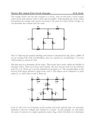
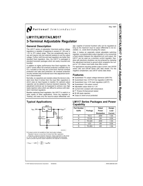
<strong>LM117</strong>/<strong><strong>LM317</strong>A</strong>/<strong>LM317</strong>3-<strong>Terminal</strong> <strong>Adjustable</strong> <strong>Regulator</strong>General DescriptionTypical ApplicationsMay 1997The <strong>LM117</strong> series of adjustable 3-terminal positive voltageregulators is capable of supplying in excess of 1.5A over a1.2V to 37V output range. They are exceptionally easy touse and require only two external resistors to set the outputvoltage. Further, both line and load regulation are better thanstandard fixed regulators. Also, the <strong>LM117</strong> is packaged instandard transistor packages which are easily mounted andhandled.In addition to higher performance than fixed regulators, the<strong>LM117</strong> series offers full overload protection available only inIC’s. Included on the chip are current limit, thermal overloadprotection and safe area protection. All overload protectioncircuitry remains fully functional even if the adjustment terminalis disconnected.Normally, no capacitors are needed unless the device is situatedmore than 6 inches from the input filter capacitors inwhich case an input bypass is needed. An optional outputcapacitor can be added to improve transient response. Theadjustment terminal can be bypassed to achieve very highripple rejection ratios which are difficult to achieve with standard3-terminal regulators.Besides replacing fixed regulators, the <strong>LM117</strong> is useful in awide variety of other applications. Since the regulator is“floating” and sees only the input-to-output differential voltage,supplies of several hundred volts can be regulated aslong as the maximum input to output differential is not exceeded,i.e., avoid short-circuiting the output.Also, it makes an especially simple adjustable switchingregulator, a programmable output regulator, or by connectinga fixed resistor between the adjustment pin and output, the<strong>LM117</strong> can be used as a precision current regulator. Supplieswith electronic shutdown can be achieved by clampingthe adjustment terminal to ground which programs the outputto 1.2V where most loads draw little current.For applications requiring greater output current, see LM150series (3A) and LM138 series (5A) data sheets. For thenegative complement, see LM137 series data sheet.Featuresn Guaranteed 1% output voltage tolerance (<strong><strong>LM317</strong>A</strong>)n Guaranteed max. 0.01%/V line regulation (<strong><strong>LM317</strong>A</strong>)n Guaranteed max. 0.3% load regulation (<strong>LM117</strong>)n Guaranteed 1.5A output currentn <strong>Adjustable</strong> output down to 1.2Vn Current limit constant with temperaturen P + Product Enhancement testedn 80 dB ripple rejectionn Output is short-circuit protected<strong>LM117</strong> Series Packages and PowerCapability<strong>LM117</strong>/<strong><strong>LM317</strong>A</strong>/<strong>LM317</strong> 3-<strong>Terminal</strong> <strong>Adjustable</strong> <strong>Regulator</strong>Part Number Rated DesignSuffix Package Power LoadDissipation CurrentK TO-3 20W 1.5AH TO-39 2W 0.5AT TO-220 20W 1.5AE LCC 2W 0.5AS TO-263 4W 1.5ADS009063-1Full output current not available at high input-output voltages*Needed if device is more than 6 inches from filter capacitors.†Optional—improves transient response. Output capacitors in the rangeof 1 µF to 1000 µF of aluminum or tantalum electrolytic are commonlyused to provide improved output impedance and rejection of transients.© 1997 National Semiconductor Corporation DS009063 www.national.com
Absolute Maximum Ratings (Note 1)If Military/Aerospace specified devices are required,please contact the National Semiconductor Sales Office/Distributors for availability and specifications.Power DissipationInternally LimitedInput-Output Voltage Differential+40V, −0.3VStorage Temperature−65˚C to +150˚CLead TemperatureMetal Package (Soldering, 10 seconds)300˚CPlastic Package (Soldering, 4 seconds)260˚CESD Tolerance (Note 5)3 kVOperating Temperature Range<strong>LM117</strong>−55˚C ≤ T J ≤ +150˚C<strong><strong>LM317</strong>A</strong>−40˚C ≤ T J ≤ +125˚C<strong>LM317</strong>0˚C ≤ T J ≤ +125˚CPreconditioningThermal Limit Burn-In All Devices 100%Electrical Characteristics (Note 3)Specifications with standard type face are for T J= 25˚C, and those with boldface type apply over full Operating TemperatureRange. Unless otherwise specified, V IN −V OUT= 5V, and I OUT= 10 mA.Parameter Conditions <strong>LM117</strong> (Note 2) UnitsMin Typ MaxReference VoltageV3V ≤ (V IN −V OUT ) ≤ 40V, 1.20 1.25 1.30 V10 mA ≤ I OUT ≤ I MAX ,P≤P MAXLine Regulation 3V ≤ (V IN −V OUT ) ≤ 40V (Note 4) 0.01 0.02 %/V0.02 0.05 %/VLoad Regulation 10 mA ≤ I OUT ≤ I MAX (Note 4) 0.1 0.3 %0.3 1 %Thermal Regulation 20 ms Pulse 0.03 0.07 %/WAdjustment Pin Current 50 100 µAAdjustment Pin Current Change 10 mA ≤ I OUT ≤ I MAX 0.2 5 µA3V ≤ (V IN −V OUT ) ≤ 40VTemperature Stability T MIN ≤ T J ≤ T MAX 1 %Minimum Load Current (V IN −V OUT ) = 40V 3.5 5 mACurrent Limit(V IN −V OUT ) ≤ 15VK Package 1.5 2.2 3.4 AH, K Packages 0.5 0.8 1.8 A(V IN −V OUT ) = 40VK Package 0.3 0.4 AH, K Packages 0.15 0.2 ARMS Output Noise, % of V OUT 10 Hz ≤ f ≤ 10 kHz 0.003 %Ripple Rejection Ratio V OUT= 10V, f = 120 Hz, 65 dBC ADJ= 0µFV OUT= 10V, f = 120 Hz, 66 80 dBC ADJ= 10 µFLong-Term Stability T J= 125˚C, 1000 hrs 0.3 1 %Thermal Resistance, K Package 2.3 3 ˚C/WJunction-to-Case H Package 12 15 ˚C/WE Package˚C/WThermal Resistance, Junction- K Package 35 ˚C/Wto-Ambient (No Heat Sink) H Package 140 ˚C/WE Package˚C/Wwww.national.com 2
Electrical Characteristics (Note 3)Specifications with standard type face are for T J= 25˚C, and those with boldface type apply over full Operating TemperatureRange. Unless otherwise specified, V IN −V OUT= 5V, and I OUT= 10 mA.Parameter Conditions <strong><strong>LM317</strong>A</strong> <strong>LM317</strong> UnitsMin Typ Max Min Typ MaxReference Voltage 1.238 1.250 1.262 V3V ≤ (V IN −V OUT ) ≤ 40V, 1.225 1.250 1.270 1.20 1.25 1.30 V10 mA ≤ I OUT ≤ I MAX ,P≤P MAXLine Regulation 3V ≤ (V IN −V OUT ) ≤ 40V (Note 4) 0.005 0.01 0.01 0.04 %/V0.01 0.02 0.02 0.07 %/VLoad Regulation 10 mA ≤ I OUT ≤ I MAX (Note 4) 0.1 0.5 0.1 0.5 %0.3 1 0.3 1.5 %Thermal Regulation 20 ms Pulse 0.04 0.07 0.04 0.07 %/WAdjustment Pin Current 50 100 50 100 µAAdjustment Pin Current10 mA ≤ I OUT ≤ I MAX 0.2 5 0.2 5 µAChange3V ≤ (V IN −V OUT ) ≤ 40VTemperature Stability T MIN ≤ T J ≤ T MAX 1 1 %Minimum Load Current (V IN −V OUT ) = 40V 3.5 10 3.5 10 mACurrent Limit(V IN −V OUT ) ≤ 15VK, T, S Packages 1.5 2.2 3.4 1.5 2.2 3.4 AH Package 0.5 0.8 1.8 0.5 0.8 1.8 A(V IN −V OUT ) = 40VK, T, S Packages 0.15 0.4 0.15 0.4 AH Package 0.075 0.2 0.075 0.2 ARMS Output Noise, % of V OUT 10 Hz ≤ f ≤ 10 kHz 0.003 0.003 %Ripple Rejection Ratio V OUT= 10V, f = 120 Hz, 65 65 dBC ADJ= 0µFV OUT= 10V, f = 120 Hz, 66 80 66 80 dBC ADJ= 10 µFLong-Term Stability T J= 125˚C, 1000 hrs 0.3 1 0.3 1 %Thermal Resistance, Junction- K Package 2.3 3 ˚C/Wto-Case H Package 12 15 12 15 ˚C/WT Package 4 5 4 ˚C/WThermal Resistance, Junction- K Package 35 35 ˚C/Wto-Ambient (No Heat Sink) H Package 140 140 ˚C/WT Package 50 50 ˚C/WS Package (Note 6) 50 50 ˚C/WNote 1: Absolute Maximum Ratings indicate limits beyond which damage to the device may occur. Operating Ratings indicate conditions for which the device is intendedto be functional, but do not guarantee specific performance limits. For guaranteed specifications and test conditions, see the Electrical Characteristics. Theguaranteed specifications apply only for the test conditions listed.Note 2: Refer to RETS117H drawing for the <strong>LM117</strong>H, or the RETS117K for the <strong>LM117</strong>K military specifications.Note 3: Although power dissipation is internally limited, these specifications are applicable for maximum power dissipations of 2W for the TO-39 and 20W for theTO-3, TO-220, and TO-263. I MAX is 1.5A for the TO-3, TO-220, and TO-263 packages and 0.5A for the TO-39 package. All limits (i.e., the numbers in the Min. andMax. columns) are guaranteed to National’s AOQL (Average Outgoing Quality Level).Note 4: Regulation is measured at a constant junction temperature, using pulse testing with a low duty cycle. Changes in output voltage due to heating effects arecovered under the specifications for thermal regulation.Note 5: Human body model, 100 pF discharged through a 1.5 kΩ resistor.Note 6: If the TO-263 package is used, the thermal resistance can be reduced by increasing the PC board copper area thermally connected to the package: Using0.5 square inches of copper area. θ JA is 50˚C/W; with 1 square inch of copper area, θ JA is 37˚C/W; and with 1.6 or more square inches of copper area, θ JA is 32˚C/W.3 www.national.com
Typical Performance CharacteristicsOutput Capacitor = 0 µF unless otherwise notedLoad RegulationCurrent LimitAdjustment CurrentDS009063-37DS009063-38DS009063-39Dropout VoltageTemperature StabilityMinimum Operating CurrentDS009063-40DS009063-41DS009063-42Ripple RejectionRipple RejectionRipple RejectionDS009063-43DS009063-44DS009063-45www.national.com 4
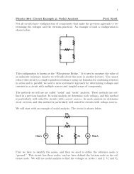
Application Hints (Continued)DS009063-6FIGURE 2. <strong>Regulator</strong> with Line Resistance in OutputLeadWith the TO-3 package, it is easy to minimize the resistancefrom the case to the set resistor, by using two separate leadsto the case. However, with the TO-39 package, care shouldbe taken to minimize the wire length of the output lead. Theground of R2 can be returned near the ground of the load toprovide remote ground sensing and improve load regulation.Protection DiodesWhen external capacitors are used with any IC regulator it issometimes necessary to add protection diodes to preventthe capacitors from discharging through low current pointsinto the regulator. Most 10 µF capacitors have low enoughinternal series resistance to deliver 20A spikes whenshorted. Although the surge is short, there is enough energyto damage parts of the IC.When an output capacitor is connected to a regulator andthe input is shorted, the output capacitor will discharge intothe output of the regulator. The discharge current dependson the value of the capacitor, the output voltage of the regulator,and the rate of decrease of V IN . In the <strong>LM117</strong>, this dischargepath is through a large junction that is able to sustain15A surge with no problem. This is not true of other types ofpositive regulators. For output capacitors of 25 µF or less,there is no need to use diodes.The bypass capacitor on the adjustment terminal can dischargethrough a low current junction. Discharge occurswhen either the input or output is shorted. Internal to the<strong>LM117</strong> is a 50Ω resistor which limits the peak discharge current.No protection is needed for output voltages of 25V orless and 10 µF capacitance. Figure 3 shows an <strong>LM117</strong> withprotection diodes included for use with outputs greater than25V and high values of output capacitance.DS009063-7D1 protects against C1D2 protects against C2FIGURE 3. <strong>Regulator</strong> with Protection Diodeswww.national.com 6
Schematic DiagramTypical ApplicationsDS009063-85V Logic <strong>Regulator</strong> with Electronic Shutdown*Slow Turn-On 15V <strong>Regulator</strong>DS009063-3DS009063-9*Min. output ≈ 1.2V<strong>Adjustable</strong> <strong>Regulator</strong> with Improved Ripple RejectionHigh Stability 10V <strong>Regulator</strong>DS009063-10†Solid tantalum*Discharges C1 if output is shorted to groundDS009063-117 www.national.com
Typical Applications (Continued)High Current <strong>Adjustable</strong> <strong>Regulator</strong>DS009063-12‡Optional—improves ripple rejection†Solid tantalum*Minimum load current = 30 mA0 to 30V <strong>Regulator</strong>Power FollowerDS009063-13Full output current not available at high input-output voltagesDS009063-14www.national.com 8
Typical Applications (Continued)5A Constant Voltage/Constant Current <strong>Regulator</strong>DS009063-15†Solid tantalum*Lights in constant current mode1A Current <strong>Regulator</strong>1.2V–20V <strong>Regulator</strong> withMinimum Program CurrentHigh Gain AmplifierDS009063-16*Minimum load current ≈ 4mADS009063-17DS009063-189 www.national.com
Typical Applications (Continued)Low Cost 3A Switching <strong>Regulator</strong>DS009063-19†Solid tantalum*Core—Arnold A-254168-2 60 turns4A Switching <strong>Regulator</strong> with Overload ProtectionDS009063-20†Solid tantalum*Core—Arnold A-254168-2 60 turnsPrecision Current LimiterDS009063-21www.national.com 10
Typical Applications (Continued)Tracking PreregulatorDS009063-22Current Limited Voltage <strong>Regulator</strong>DS009063-23(Compared to <strong>LM117</strong>’s higher current limit)—At 50 mA output only 3 ⁄4 volt of drop occurs in R 3 and R 4Adjusting Multiple On-Card <strong>Regulator</strong>s with Single Control*DS009063-24*All outputs within ±100 mV†Minimum load—10 mA11 www.national.com
Typical Applications (Continued)AC Voltage <strong>Regulator</strong>DS009063-2512V Battery ChargerDS009063-26Use of R S allows low charging rates with fully charged battery.50 mA Constant Current Battery ChargerDS009063-27www.national.com 12
Typical Applications (Continued)<strong>Adjustable</strong> 4A <strong>Regulator</strong>DS009063-28Current Limited 6V ChargerDigitally Selected Outputs*Sets peak current (0.6A for 1Ω)**The 1000 µF is recommended to filter out input transientsDS009063-29*Sets maximum V OUTDS009063-213 www.national.com
Connection Diagrams(TO-3)Metal Can Package(TO-39)Metal Can Package(TO-220)Plastic PackageDS009063-30CASE IS OUTPUTBottom ViewSteel PackageOrder Number <strong>LM117</strong>K STEELor <strong>LM317</strong>K STEELSee NS Package Number K02AOrder Number <strong>LM117</strong>K/883See NS Package Number K02CDS009063-31CASE IS OUTPUTBottom ViewOrder Number <strong>LM117</strong>H, <strong>LM117</strong>H/883,<strong><strong>LM317</strong>A</strong>H or <strong>LM317</strong>HSee NS Package Number H03A(TO-263) Surface-Mount PackageTop ViewDS009063-35DS009063-36Side ViewOrder Number<strong><strong>LM317</strong>A</strong>S or <strong>LM317</strong>SSee NS PackageNumber TS3BDS009063-32Front ViewOrder Number <strong><strong>LM317</strong>A</strong>T or<strong>LM317</strong>TSee NS Package Number T03BCeramic LeadlessChip CarrierDS009063-34Top ViewOrder Number <strong>LM117</strong>E/883See NS Package Number E20Awww.national.com 14
Physical Dimensions inches (millimeters) unless otherwise notedCeramic Leadless Chip CarrierOrder Number <strong>LM117</strong>E/883NS Package Number E20Awww.national.com 16
Physical Dimensions inches (millimeters) unless otherwise noted (Continued)(TO-39) Metal Can PackageOrder Number <strong>LM117</strong>H, <strong>LM117</strong>H/883, <strong><strong>LM317</strong>A</strong>H or <strong>LM317</strong>HNS Package Number H03ATO-3 Metal Can Package (K)Order Number <strong>LM117</strong>K STEEL,<strong>LM117</strong>K STEEL/883, or <strong>LM317</strong>K STEELNS Package Number K02A17 www.national.com
Physical Dimensions inches (millimeters) unless otherwise noted (Continued)TO-3 Metal Can Package (K)Mil-Aero ProductOrder Number <strong>LM117</strong>K/883NS Package Number K02Cwww.national.com 18
Physical Dimensions inches (millimeters) unless otherwise noted (Continued)(TO-220) Outline DrawingOrder Number <strong><strong>LM317</strong>A</strong>T or <strong>LM317</strong>TNS Package Number T03B19 www.national.com