Modeling of scattering and depolarizing electro-optic ... - CiteSeerX
Modeling of scattering and depolarizing electro-optic ... - CiteSeerX
Modeling of scattering and depolarizing electro-optic ... - CiteSeerX

Create successful ePaper yourself
Turn your PDF publications into a flip-book with our unique Google optimized e-Paper software.
<strong>Modeling</strong> <strong>of</strong> <strong>scattering</strong> <strong>and</strong> <strong>depolarizing</strong><strong>electro</strong>-<strong>optic</strong> devices. I. Characterization<strong>of</strong> lanthanum-modified lead zirconate titanatePaul E. Shames, Pang Chen Sun, <strong>and</strong> Yeshaiahu FainmanWe describe a new method <strong>of</strong> modeling <strong>electro</strong>-<strong>optic</strong> EO devices, such as lanthanum-modified leadzirconate titanate polarization modulators, that resolves two deficiencies <strong>of</strong> current methods: i theinclusion <strong>of</strong> depolarization effects resulting from <strong>scattering</strong> <strong>and</strong> ii saturation <strong>of</strong> the EO response atstrong electric-field strengths. Our approach to modeling depolarization is based on describing thetransmitted <strong>optic</strong>al field by superposition <strong>of</strong> a deterministic polarized wave <strong>and</strong> a scattered, r<strong>and</strong>omlypolarized, stochastic wave. Corresponding Jones matrices are used to derive a Mueller matrix todescribe the wave propagation in <strong>scattering</strong> <strong>and</strong> <strong>depolarizing</strong> EO media accurately. A few simple <strong>optic</strong>almeasurements can be used to find the nonlinear behavior <strong>of</strong> the EO phase function, which is shown todescribe accurately the material’s EO behavior for weak <strong>and</strong> strong applied electric fields. © 1998Optical Society <strong>of</strong> AmericaOCIS codes: 160.2100, 190.5890, 080.2730, 190.3270, 260.2130.1. IntroductionPolycrystalline lanthanum-modified lead zirconatetitanate PLZT is an <strong>electro</strong>-<strong>optic</strong> EO material thathas many advantages over single-crystal EO materials,including ease <strong>of</strong> manufacturing, low operatingvoltages, <strong>and</strong> reduced long-range strain effects. 1PLZT-based devices with compositions <strong>of</strong> 8.8–9.56535 are used in a variety <strong>of</strong> opto<strong>electro</strong>nic applicationsincluding high-speed scanning, 2 dynamiclenses, 3 <strong>optic</strong>al switches, 4 <strong>and</strong> shutters <strong>and</strong> eyeprotectiondevices. 5Bulk PLZT can be highly <strong>scattering</strong>, which hasconstrained the geometry <strong>of</strong> many devices to the use<strong>of</strong> thin wafers with interdigital surface-<strong>electro</strong>de designs.These design geometries can require the application<strong>of</strong> very strong electric fields. For example,consider a programmable phased-array device thatuses PLZT 9.06535 with surface <strong>electro</strong>des separatedby 40 m. To achieve an average phase shift<strong>of</strong> for light passing through such a deviceThe authors are with the Department <strong>of</strong> Electrical <strong>and</strong> ComputerEngineering, University <strong>of</strong> California, San Diego, 9500 GilmanDrive, La Jolla, California 92093-0407.Received 13 October 1997; revised manuscript received 2 March1998.0003-693598173717-09$15.000© 1998 Optical Society <strong>of</strong> Americarequires applying field strengths greater than 1.5 10 6 Vm throughout the gap region. At these fieldstrengths, we have found that even thin wafers <strong>of</strong>PLZT become highly <strong>scattering</strong>. 6 This <strong>scattering</strong>can significantly reduce the <strong>optic</strong>al signal strength,create <strong>of</strong>f-axis noise, <strong>and</strong> depolarize the transmittedlight. 7 Therefore design geometries that reduce theoperating electric-field strength <strong>and</strong> the associated<strong>scattering</strong> <strong>and</strong> <strong>depolarizing</strong> effects are critical forPLZT-based devices.Computer-aided design <strong>and</strong> modeling, or CAD–CAM, can be a very useful tool in the development <strong>of</strong>EO device geometries for improved performance.Traditionally, 8–13 these EO devices are modeled byuse <strong>of</strong> a simple Jones calculus 14 model that cannotaccount for the effects <strong>of</strong> depolarization. Additionally,PLZT 8.8–9.56535 device phase modulation isusually modeled by a classical Kerr quadratic EOeffect 1,3 or a combination <strong>of</strong> linear <strong>and</strong> quadratic effects5,15,16 i.e., second-order effects. These modelsfail to describe accurately both the weak <strong>and</strong> thestrong electric-field-induced EO response.To achieve accurate computer simulation, particularlyfor devices that experience strong electric fields,it is necessary to take into account <strong>scattering</strong> <strong>and</strong> theresultant depolarization effects, <strong>and</strong> a higher thansecond-order EO phase function must be used. Toderive a model that can account for depolarization,10 June 1998 Vol. 37, No. 17 APPLIED OPTICS 3717
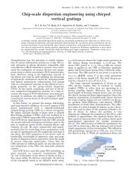
we describe the <strong>optic</strong>al field transmitted through a<strong>scattering</strong> EO medium by superposition <strong>of</strong> a deterministicpolarized wave <strong>and</strong> a scattered, r<strong>and</strong>omlypolarized, stochastic wave. The vector properties <strong>of</strong>such <strong>optic</strong>al fields are then described by the correspondingsuperposition <strong>of</strong> a deterministic <strong>and</strong> a stochasticJones matrix. The resulting Jones matricesare used to derive a Mueller matrix to describe accuratelythe wave propagation in a <strong>scattering</strong> EO medium.A few simple <strong>optic</strong>al measurements can beused to characterize the material for the Mueller matrixcoefficients. In addition, using the same set <strong>of</strong>measurements we solve for an EO function that accuratelydescribes the change in relative phase betweentwo orthogonal polarization componentsparallel <strong>and</strong> perpendicular to an applied electric field.Applying this method to PLZT 8.8–9.56535, wefind that, in contrast to the traditional quadratic EOmodel, the derived EO phase response is best fittedwith a fifth-order polynomial function. This higherorderphase function accounts for the experimentallyobserved EO response that is due to weak as well asstrong applied electric fields.In this manuscript part 1 <strong>of</strong> two papers we deriveour simplified Mueller matrix model <strong>and</strong> discuss itsapplication to characterizing PLZT; the application <strong>of</strong>this technique to device modeling is reported in thesecond paper, in this issue see pp. 3726–3734. Weshow how a few simple <strong>optic</strong>al transmission measurementsaccount fully for the electric-field-induced response<strong>of</strong> the material while allowing for the solution<strong>of</strong> an accurate EO function. In Section 2 we beginour discussion with a review <strong>of</strong> the various electricfield-inducedeffects that are included in our model.In Section 3 we use Stokes vectors <strong>and</strong> Mueller matricesto describe <strong>optic</strong>al beam transmission through<strong>depolarizing</strong> systems. We then present in Section 4our experimental characterization <strong>of</strong> a sample <strong>of</strong>PLZT material <strong>and</strong> compare the results to our newmodel. Finally, in Section 5 we give a summary <strong>and</strong>conclusions.Fig. 1. a PLZT sample with transverse <strong>electro</strong>des oriented togenerate an electric field along the y axis. A crossed polarizer–analyzer pair is oriented at 45° <strong>and</strong> 45°, respectively, to the yaxis. Linear polarized light is rotated 90° if the induced birefringenceresults in a phase difference <strong>of</strong> . b Experimentalmeasurement results filled circles <strong>of</strong> the transmission intensity <strong>of</strong>light passing through the system as a function <strong>of</strong> the electric-fieldstrength for a PLZT sample <strong>of</strong> L 388 m. The solid curveshows the simulated performance by use <strong>of</strong> Eq. 1 <strong>and</strong> a best-fitquadratic EO model. To account for the weak EO response at lowelectric fields, a constant field <strong>of</strong> E 0 2 10 5 Vm, opposite to theapplied field direction, is included in the model.2. Electric-Field-Induced EffectsPLZT is a ferroelectric ceramic material composed <strong>of</strong>crystallites, varying 1–10 m in grain size, 17 whosematerial phase <strong>and</strong> electrical characteristics aresensitive to changes in material composition, temperature,<strong>and</strong> applied electric field. In the absence <strong>of</strong> anapplied electric field the PLZT is <strong>optic</strong>ally isotropic,whereas an applied electric field induces refractiveindexanisotropy. This leads to an <strong>optic</strong>al phase difference for two orthogonally polarized lightcomponents passing through the material e.g.,parallel to <strong>and</strong> perpendicular to the direction <strong>of</strong> theapplied field. Figure 1a shows a typical experimentalsetup for the measurement <strong>of</strong> transmittedlight intensity through a PLZT sample by use <strong>of</strong>crossed polarizers set at 45° relative to the appliedfielddirection. Traditionally, the relative phasechange i.e., the EO response <strong>of</strong> the material is assumedto be quadratic, that is, E 2 , where E is themagnitude <strong>of</strong> the applied electric field. The transmissionintensity I <strong>of</strong> light through such a system isusually modeled by use <strong>of</strong> Jones calculus by the relationI 1 2 sin2 2 , (1)where the intensity reaches maxima <strong>and</strong> minima seeFig. 1b when n where n is an integer.However, a typical experimental result <strong>of</strong> intensitymeasurements as shown in Fig. 1b illustrates how areal device’s EO response departs from this simpleanalytic model. At low field strength there is almostno EO response, <strong>and</strong> the quadratic phase modelneeds to be shifted i.e., E E 0 2 to take thisweak response into account. At high field strengthwe can see that the EO effect diminishes i.e., theperiod increases compared to the quadratic approx-3718 APPLIED OPTICS Vol. 37, No. 17 10 June 1998
imation. We can conclude that the quadratic EOmodel is accurate for only a limited range <strong>of</strong> the appliedelectric-field strength. The technique to generatea more accurate EO phase function, which canaccount for the weak <strong>and</strong> the strong electric-field response<strong>of</strong> this material, is discussed in Section 4.In Fig. 1b we can also see that the transmitted<strong>optic</strong>al intensity, as well as the contrast ratio, decreaseas functions <strong>of</strong> the applied electric-fieldstrength. The decrease in the measured intensity isdue to <strong>scattering</strong>, which in PLZT has been found to bea function <strong>of</strong> material composition, 1 grain size, 17 <strong>and</strong>strength <strong>of</strong> the applied electric field. 7 The fieldinduced<strong>scattering</strong> can be related to index changes atgrain <strong>and</strong> domain boundaries <strong>and</strong> with small strainrelievingdomain formations. 18 For the majority <strong>of</strong>spatial light modulator devices, <strong>scattering</strong> introducesunwanted signal attenuation. Furthermore, thescattered light is depolarized, 7 <strong>and</strong> the portion thatremains within the solid angle <strong>of</strong> the system’s exitpupil creates noise in the detected signal. As theapplied electric field is increased, the intensity <strong>of</strong> thedetected depolarized light also increases, which canbe seen as increases in the minima intensities for thetransmission curve shown in Fig. 1b. At high fieldstrength the light is completely unpolarized, <strong>and</strong> wecan no longer detect any change in relative phase.3. Mueller Matrix Model for PLZT-Based DevicesJones 1 2 vectors <strong>and</strong> 2 2 matrices are convenienttools for describing polarized light propagatingthrough non<strong>depolarizing</strong> <strong>optic</strong>al devices <strong>and</strong> systems.However, to model <strong>depolarizing</strong> <strong>optic</strong>al devices suchas PLZT-based modulators, one must use a higherordermatrix representation. 19 In our case we useStokes vectors 20 <strong>and</strong> Mueller matrices 21,22 1 4 <strong>and</strong>4 4, respectively. Consider a normally incidentquasi-monochromatic <strong>optic</strong>al beam with a mean frequency. Using a right-h<strong>and</strong>ed Cartesian coordinatesystem, as shown in Fig. 1a, with the direction<strong>of</strong> propagation along the z axis, we obtain the twoorthogonal complex electric-field components byE x t E 1 texpi 1 t 2t,E y t E 2 texpi 2 t 2t, (2)where the absolute phase 1 t, 2 t <strong>and</strong> amplitudesE 1 t, E 2 t <strong>of</strong> each component are real functions<strong>of</strong> time. The Stokes parameters, which areused to describe the polarization state <strong>of</strong> the light, aregiven in vector form by0SS S 13E 2 1 E 2 2 E 2 1 E 2 2 (3)S 2 2E 1 E 2 cos S 2E 1 E 2 sin t,where t 1 t 2 t is the relative phase differencebetween the two orthogonal components.Transformation <strong>of</strong> the Stokes vector by a nonimaging21 device, such as a polarizer or a phase retarder,is described by a 4 4 Mueller matrix M. An <strong>optic</strong>alsystem comprising a cascade <strong>of</strong> N such devices isrepresented by the product <strong>of</strong> their respective Muellermatrices:M system M N M N1 ...M n ...M 1 , (4)where M system is the Mueller matrix representation <strong>of</strong>the entire <strong>optic</strong>al system <strong>and</strong> M n is the matrix <strong>of</strong> thenth device <strong>of</strong> the system. The transformation <strong>of</strong> theStokes vector by an <strong>optic</strong>al system is given byS out M system S in . (5)Given a known Jones matrix J see Appendix A,Subsection 1, describing a non<strong>depolarizing</strong> <strong>optic</strong>alelement, the corresponding Mueller matrix is given 21by the transformationM TJ J*T 1 , (6)where the symbol V denotes the Kronecker product 23see Appendix A, Subsection 2, the asterisk denotesthe complex conjugate, <strong>and</strong> T is the 4 4 lineartransformation between the Stokes parameters <strong>and</strong>the coherency matrix parameters 24 see Appendix A,Subsection 3. As an example, for an ideal non<strong>scattering</strong><strong>and</strong> non<strong>depolarizing</strong> EO device the Jones matrixis the same as a linear phase retarder <strong>and</strong> isgiven 10 byJ expi 2 00 expi 2, (7)where is the relative phase difference for the x- <strong>and</strong>y-polarization components <strong>of</strong> the light. SubstitutingEqs. 7, A5, <strong>and</strong> A9 into Eq. 6, we find the correspondingMueller matrix 25 :0 0 00 1 0 0M PLZTideal 1 . (8)0 0 cos sin0 0 sin cosHowever, for a real PLZT device that has r<strong>and</strong>om<strong>scattering</strong> <strong>and</strong> depolarization one must use an ensembleaverage <strong>of</strong> Jones matrices. 24 To create suchan ensemble, we distinguish in our model betweenthe spatial frequency <strong>of</strong> the light incident upon <strong>and</strong>the spatial frequency <strong>of</strong> the light exiting the PLZTdevice, i.e., because <strong>of</strong> <strong>scattering</strong> we expect that thelight exiting the device will have additional spatialfrequencycomponents. For example, in our experimentwe use a plane wave, i.e., with a single spatialfrequency, which we define as the dc spatialfrequency<strong>optic</strong>al field parallel to the <strong>optic</strong>al axis,incident upon our PLZT device, whereas the exitinglight is scattered <strong>and</strong> consists <strong>of</strong> a wide b<strong>and</strong> <strong>of</strong>spatial-frequency components. Under the assumptionthat the <strong>scattering</strong> field from every point can bemodeled as a zero-mean Gaussian r<strong>and</strong>om process, 26we can separate the <strong>optic</strong>al field transmitted throughthe PLZT device into two components: a nonscat-10 June 1998 Vol. 37, No. 17 APPLIED OPTICS 3719
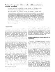
Fig. 2. Experimental setup for the characterization <strong>and</strong> modeling<strong>of</strong> PLZT samples. The PLZT sample is fully illuminated to avoidlocalized photorefractive effects. The low-pass filter was onlyused for experimental measurements for which the scattered fieldsneeded to be filtered out.tered dc field <strong>and</strong> the scattered field. By using alow-pass filter see Fig. 2 in the spatial Fouriertransform plane <strong>of</strong> the output lens, we are able t<strong>of</strong>ilter the scattered light out from the output signal.Experimental measurements <strong>of</strong> such a system showsee Fig. 3 that the dc field is polarized <strong>and</strong> has anegligibly small scattered or depolarized component,which justifies the use <strong>of</strong> our superposition model.Therefore we conclude that only the <strong>scattering</strong> fieldcontributes to the depolarization, which can be describedby an ensemble <strong>of</strong> r<strong>and</strong>omly polarized fields. 24We describe a typical PLZT-device Jones matrix bya superposition <strong>of</strong> a deterministic matrix, which accountsfor the DC field, <strong>and</strong> an ensemble <strong>of</strong> nondeterministicmatrices, which represents the scatteredunpolarized field, indicated by the superscript e,given byJ e a expi 2 00 b expi 2 u 1a expi 2 u 1eu 4eu 3eu 4u 3eu 2b expi 2 u 2e, (9)Fig. 3. Using a low-pass filter see Fig. 2, we remove the scatteredlight from the detected signal. The remaining dc componentcontains no <strong>optic</strong>al bias, allowing us to conclude that the dc light ispolarized. In this measurement we used parallel polarizers,which resulted in a maximum intensity at zero voltage. ThePLZT sample used was 1 mm thick, which accounts for the increasein phase variation compared with Fig. 1b.where a <strong>and</strong> b are the real transmittance amplitudes<strong>of</strong> the nonscattered light, is the relative phase differencefor the two orthogonal polarization components,<strong>and</strong> u i are the complex transmittanceeamplitudes that account for the r<strong>and</strong>omly polarizedlight. The coefficients u 1 <strong>and</strong> u 2 represent the amplitudes<strong>of</strong> the depolarized x <strong>and</strong> y light components,respectively, <strong>and</strong> u 3 <strong>and</strong> u 4 are the coupled or crossdepolarizationamplitudes.We assume that u e i are independent r<strong>and</strong>om variableswith a zero mean, u i e 0, <strong>and</strong> under theensemble over a large detection area e.g., a powermeter much larger than the coherence area <strong>of</strong> thescattered light the unpolarized components can beconsidered uncorrelated with each other as well aswith the deterministic polarized components, i.e.,u i u k * e 0 if i kU i if i k , (10)u i expj 2e 0, (11)where . .. e is shorth<strong>and</strong> notation for the averageover the ensemble <strong>and</strong> U i u i 2 . The transformationfor the ensemble average <strong>of</strong> Jones matrices intoa Mueller matrix then takes the form 24 <strong>of</strong>M TJ e J e* e T 1 . (12)Using Eqs. 10 <strong>and</strong> 11 allows the resultant Muellermatrix to be written as2M PLZT 1A B U 11 U 2 U 3 U 4 2 A B U 1 U 2 U 3 U 4 0 012 A B U 11 U 2 U 3 U 4 2 A B U 1 U 2 U 3 U 4 0 0 , (13)0 0 AB cos AB sin0 0 AB sin AB cos3720 APPLIED OPTICS Vol. 37, No. 17 10 June 1998
where we have used the definitions A a 2 <strong>and</strong> B b 2 , which represent the intensity <strong>of</strong> the nonscatteredlight for the two orthogonally polarized light components,<strong>and</strong> U i are the intensities <strong>of</strong> the depolarizationcomponents as defined in Eq. 10. As discussed inSection 2, the nonscattered <strong>and</strong> depolarized intensitiesas well as the change in phase are all functions <strong>of</strong>applied electric field. However, for simplicity we usethe abbreviated formsAE A, BE B,U i E U i , E , (14)where E is the magnitude <strong>of</strong> the applied electric field.A similar matrix 27 has been obtained for a reflectorwith incoherent <strong>scattering</strong> i.e., depolarization.However, in that case the cross-<strong>scattering</strong> is assumedto be negligible i.e., U 3 U 4 0. Applying such amatrix in our system, we find that the resultantStokes parameters do not coincide with our experimentaldata. Therefore we need to include thecross-depolarization terms in our derivation.Having derived an appropriate Mueller matrix fora PLZT device, we need to calculate the transformation<strong>of</strong> our complete experimental <strong>optic</strong>al system <strong>and</strong>determine what set <strong>of</strong> intensity measurements willallow us to solve for the unknown coefficients. Ourmeasurement apparatus uses normally incident coherentmonochromatic light, polarized at 45° relativeto the x axis see Fig. 1a. For our experiments theincident Stokes vector is determined by use <strong>of</strong> Eq. 3with the maximum intensity normalized to 1 <strong>and</strong>under the assumption that E 1 t E 2 t <strong>and</strong> t isconstant, which result inS in 1010. (15)The light passes through a cascade <strong>of</strong> <strong>optic</strong>al componentsmade up <strong>of</strong> a polarizer, a PLZT device, <strong>and</strong> asecond polarizer. The Mueller matrix for an idealpolarizer 25 isM Pol 1 21 cos2 sin2 0cos2 cos 2 2 cos2sin2 0sin2 cos2sin2 sin 2 2 00 0 0 0,(16)where is the angle between the polarizer axis <strong>and</strong>the x axis. The output Stokes vector is obtainedwith the transformation given by Eq. 5 applied toour system, yieldingS out M Pol a M PLZT M Pol p S in , (17)where p is the angle <strong>of</strong> the first polarizer <strong>and</strong> a is theangle <strong>of</strong> the second polarizer usually referred to asthe polarizer <strong>and</strong> the analyzer, respectively, withM PLZT from Eq. 13.From the Mueller matrix Eq. 13 for the PLZTdevice we have seven unknown coefficients: A, B,U 1 , U 2 , U 3 , U 4 , <strong>and</strong> , which represent the intensities<strong>of</strong> the nonscattered polarized light, the depolarizedlight, <strong>and</strong> the change in the relative phase betweenthe orthogonally polarized components. Our objectiveis to find equations <strong>of</strong> measured intensity thatallow us to solve for the seven unknowns that willcharacterize the PLZT sample as functions <strong>of</strong> E, theapplied electric-field strength. The first component<strong>of</strong> the output Stokes vector represents the measured<strong>optic</strong>al intensity. It can be described as a function <strong>of</strong>the two polarizer angles: S 0out I a , p. Using fiveconvenient pairs <strong>of</strong> polarizer–analyzer angles in Eq.17, we solve for S 0out<strong>and</strong> findI 45°,45° 1 4 A B U 1 U 2 U 3 U 4 2AB cos, (18)I 0°,0° 1 2 A U 1, (19)I 90°,90° 1 2 B U 2, (20)I 0°,90° 1 2 U 3, (21)I 90°,0° 1 2 U 4, (22)where we have normalized the incident light intensity.Equations 19 <strong>and</strong> 20 each contain one polarizedcomponent <strong>and</strong> one depolarized component.By subtracting the depolarized component by use <strong>of</strong>the low-pass filtering technique described above, wecan reduce these equations toI 0°,0°Filter 1 A, (23)2I 90°,90°Filter 1 B. (24)2Here we normalize the measurements with respect tothe intensity at zero applied voltage after the lowpassfilter. Including Eqs. 23 <strong>and</strong> 24, we havederived seven equations Eqs. 18–24, representingseven experimental measurements required to characterizethe PLZT sample fully, i.e., the seven coefficientsthat represent the intensity <strong>of</strong> the polarizedcomponents A <strong>and</strong> B, the depolarized componentsU 1 , U 2 , U 3 , <strong>and</strong> U 4 , <strong>and</strong> the change in relative phase.If we wish to reduce the number <strong>of</strong> required measurements,we can assume that the <strong>scattering</strong> isisotropic. This results in the amplitudes <strong>and</strong> intensities<strong>of</strong> the polarized components being identi-10 June 1998 Vol. 37, No. 17 APPLIED OPTICS 3721
This decomposition shows us how our ensembleaveragederivation <strong>and</strong> isotropic-<strong>scattering</strong> assumptionsresult in two known Mueller matrices: Thefirst is a combination <strong>of</strong> a linear attenuator <strong>and</strong> retardermatrix, 28 <strong>and</strong> the second is a depolarizer. 29Fig. 4. Seven <strong>optic</strong>al intensity measurements normalized to illustratethe envelope functionality <strong>of</strong> the vertical <strong>and</strong> horizontalcomponents to the I 45°,45° data.cal, i.e., A B, <strong>and</strong> the various depolarization intensitycoefficients U i would also be equivalent, i.e.,Equation 13 reduces toU U i , i 1, 2, 3, 4. (25) 2U 0 0 00 A 0 0M PLZT A . (26)0 0 A cos A sin0 0 A sin A cosWe now require only three equations to solve for thecoefficients, for example:I 45°,45° 1 A 2U A cos, (27)2I 0°,0° I 90°,90° 1 A U, (28)2I 0°,90° I 90°,0° 1 U. (29)2In Section 4 we describe experimental measurementdata Fig. 4 showing that, for the PLZT samplesused, the isotropic approximation is acceptable.Finally, the Mueller matrix <strong>of</strong> Eq. 26 can be decomposedinto deterministic <strong>and</strong> nondeterministicparts:0 0 00 A 0 0M PLZT A 0 0 A cos A sin0 0 A sin A cos0 0 00 0 0 02U(30)0 0 0 00 0 0 0.4. Experimental MeasurementsWe have developed experimental procedures that allowus to measure the effects <strong>of</strong> the electric field inPLZT on such characteristics as <strong>scattering</strong>, depolarization,<strong>and</strong> the EO response. In these experimentswe constructed a setup that produces a homogeneouselectric field within our sample that is achieved byuse <strong>of</strong> a parallel-plate capacitor configuration seeFig. 1a. By s<strong>and</strong>wiching our PLZT sample betweentwo parallel gold-plated copper plates, whichare much larger than the sample, we generate a constantelectric field inside <strong>and</strong> outside the ceramic <strong>and</strong>avoid fringing-field inhomogeneities. The distancebetween plates d <strong>and</strong> the applied voltage V give usthe electric-field strength E Vd, <strong>and</strong> the thicknessL <strong>of</strong> the PLZT is the <strong>optic</strong>al interaction length.In this experiment we use a He–Ne laser beampolarized at 45° relative to the direction <strong>of</strong> the appliedelectric field. The coherent light is transmittedthrough a spatial filter <strong>and</strong> recollimated to define thedc spatial frequency <strong>of</strong> the input <strong>optic</strong>al field illuminatingthe entire PLZT sample see Fig. 2. We usedichroic polarizers with an extinction ratio betterthan 1 10 3 . The transmitted light is captured bya lens <strong>and</strong> directed onto a Newport Si detector, Model818-SL, <strong>and</strong> the total intensity is measured with aNewport Model 835 <strong>optic</strong>al power meter.Using the experimental setup outlined above, wemeasure the transmitted <strong>optic</strong>al intensity versus anapplied electric field see Fig. 4 by using the fivepolarizer–analyzer orientations given in Eqs. 18–22. For comparison purposes we show twice theintensity values <strong>of</strong> the vertical <strong>and</strong> horizontal measurements,as we discuss below. We can see thatI 0°,0° I 90°,90° , I 0°,90° I 90°,0° . (31)Therefore in this case we may assume that theseterms are equivalent <strong>and</strong> use the isotropic <strong>scattering</strong>approximation made in deriving the simplified Muellermatrix Eq. 26. We can also see from the plotthat all the intensity curves converge to the samevalue above 1.75 10 6 Vm. This convergence indicatesthat the light becomes completely unpolarizedunder the influence <strong>of</strong> a very strong electric field.In Fig. 4 the maxima <strong>of</strong> the I 45°,45° data are approximatelyequal to the 2I 0°,0° <strong>and</strong> the 2I 90°,90° data sets,which is consistent with our equations, since themaxima values, i.e., cos 1, <strong>of</strong> Eq. 27 yieldI 45°,45°max AE UE 2I 0°,0° 2I 90°,90° . (32)Additionally, the minima areI 45°,45°min UE 2I 0°,90° 2I 90°,0° , (33)3722 APPLIED OPTICS Vol. 37, No. 17 10 June 1998
Fig. 5. Change in the relative phase calculated from measureddata for PLZT 8.96535 circles. For comparison we also showthe calculated change in phase obtained by use <strong>of</strong> a shifted E 0 1.5 10 5 Vm electric field in the st<strong>and</strong>ard quadratic model solidcurve with the quadratic EO coefficient R 17.0 10 16 mV 2 .The change in the index <strong>of</strong> refraction is calculated by use <strong>of</strong> thelinear relation L 2n.which again coincides with the measurements shownin Fig. 4. In Eqs. 32 <strong>and</strong> 33 we use a more completenotation showing the electric-field dependence<strong>of</strong> the coefficients.Substituting Eqs. 28 <strong>and</strong> 29 into Eq. 27 wesolve, using the simplified Mueller matrix, for thechange in relative 1 phase: cos I 45°,45° I 0°,0° I 0°,90°I 0°,0° I 0°,90° . (34)The calculated phase function is shown in Fig. 5.The smoothness <strong>of</strong> this curve represents the accuracy<strong>of</strong> our isotropic approximation. That is, intensitymeasurements with strong anisotropic <strong>scattering</strong> willresult in a phase function with clear discontinuities.Therefore for some materials a fine resolution <strong>of</strong> thephase function could require including the variations<strong>of</strong> transmitted intensity owing to anisotropic <strong>scattering</strong>,i.e., making all seven <strong>of</strong> the required measurementsEqs. 18–24. As we noted above see Fig.1b, upto2 10 5 Vm electric-field strength thePLZT has relatively no EO response <strong>and</strong> the phasefunction remains flat. From 2 10 5 Vmto1 10 6Vm the EO phase response is roughly quadratic, <strong>and</strong>at higher electric-field strengths the response diminishessignificantly, i.e., saturates, as discussed in Section2.Previous research has produced similar phasefunctions 1,10 that show the saturation <strong>of</strong> the EO effectat high field, with a maximum change in index <strong>of</strong>approximately 1 10 2 . However, the weak EOresponse <strong>of</strong> PLZT at low electric-field strength is <strong>of</strong>tennot present in published experimental data. Webelieve that this is due to the use <strong>of</strong> a surface<strong>electro</strong>deconfiguration to characterize the materials’EO response. 10 In this configuration the electricfield is not homogeneous, <strong>and</strong> it can be very difficultto calculate accurately the phase versus the electricfieldfunction.For simplification these PLZT compositions areusually assumed to have a quadratic EO response ora combination <strong>of</strong> a linear <strong>and</strong> a quadratic response.However, as can be seen from Fig. 5, the quadraticapproximation does not account for the saturation athigh electric fields, <strong>and</strong> neither model can account forthe weak response at low field strength. We findthat the use <strong>of</strong> a fifth-order polynomial achieves anexcellent fit to the change in phase–index versus theelectric-field data available. Although this material’sEO response is dominated by the quadratic Kerreffect, the linear Pockels response might also bepresent. The higher-order terms in the fifth-orderpolynomial fit can be associated with material constraintsthat freeze the polarizability under weakfields <strong>and</strong> limit molecular deformation under highfields.5. ConclusionIn this paper we have presented a new method forcharacterizing the polarization properties <strong>of</strong> <strong>scattering</strong><strong>and</strong> <strong>depolarizing</strong> EO materials by using as anexample PLZT 8.8–9.56535 compositions. Weshowed that the <strong>optic</strong>al field passing through bulkPLZT can be described by superposition <strong>of</strong> a nonscatteredpolarized component <strong>and</strong> a scattered depolarizedcomponent. Using the corresponding deterministic<strong>and</strong> stochastic Jones matrices, we havederived a simplified Mueller matrix representation inwhich only seven coefficients are required to describethe <strong>scattering</strong> <strong>and</strong> <strong>depolarizing</strong> EO device. UsingStokes vectors, we were then able to calculate thetransmitted <strong>optic</strong>al intensity for light passingthrough our device in terms <strong>of</strong> the seven correspondingcoefficients.By placing a PLZT device that has a parallel-plate<strong>electro</strong>de geometry between a pair <strong>of</strong> polarizers, weperform relatively simple compared with Muellermatrix ellipsometry 30 experimental measurementsto solve for the unknown coefficients. As we varythe electric potential across the PLZT device, we generatea data set describing the coefficients <strong>of</strong> <strong>scattering</strong>,depolarization, <strong>and</strong> EO phase response asfunctions <strong>of</strong> the applied electric field. Experimentalresults show practically no EO response for PLZTunder a weak electric field. This effect might not beobserved with a traditional surface-<strong>electro</strong>de geometry,since the electric field can be very high near the<strong>electro</strong>de edges, even under small applied voltages.Our characterization shows distinctly different EOresponses for weak, medium, <strong>and</strong> strong electric-fieldstrengths. Therefore, for accurate simulation <strong>of</strong>changes in phase or index <strong>of</strong> refraction resultingfrom large electric-field gradients e.g., surface<strong>electro</strong>dedevices, we must use a higher than secondorderEO model.Although PLZT has been shown to have anisotropic<strong>scattering</strong>, to reduce the number <strong>of</strong> unknowns in ourMueller matrix, we have assumed the simpler model<strong>of</strong> isotropic <strong>scattering</strong>. This can be justified on the10 June 1998 Vol. 37, No. 17 APPLIED OPTICS 3723
asis <strong>of</strong> the similarity between the measured intensitiesfor the various polarized <strong>and</strong> depolarized components.Using the experimental data shown in Fig.4, we have compared the intensities <strong>of</strong> the two orthogonalpolarized components A, B <strong>and</strong> have foundthat the average difference is less than 2%, with amaximum <strong>of</strong> 5%. Comparing the intensities <strong>of</strong> thefour depolarization-component intensities U 1 , U 2 ,U 3 , U 4 gives an average difference <strong>of</strong> less than 4%when dividing by the maximum depolarized intensity<strong>and</strong> a maximum difference <strong>of</strong> 13%. Thereforewithin a less than 5% average error we can use theisotropic-<strong>scattering</strong> approximation to simplify ourMueller matrix to have only three unknown coefficientsA, U, <strong>and</strong> <strong>and</strong> reduce the correspondingnumber <strong>of</strong> required experimental measurements.The application <strong>of</strong> our characterization study, asdiscussed in this paper, to computer-aided design <strong>and</strong>device simulation is discussed in a second paper, alsoin this issue. We also continue to characterize bulkPLZT in terms <strong>of</strong> temperature <strong>and</strong> ac electric-fielddependencies, as well as to characterize alternativeEO materials.Appendix A1. Jones Matrix FormulationFor a uniform monochromatic TE plane wave incidenton a non<strong>depolarizing</strong> <strong>optic</strong>al system, the outgoingplane wave can be described byE x J 11 E x J 12 E y ,E y J 21 E x J 22 E y ,which can be combined in matrix form as E xE y J 11 J 12J 21 J 22 E xE y ,(A1)(A2)(A3)or by the simplified notation E JE, where thetransformation by the <strong>optic</strong>al element or system,is called the Jones matrix. 20J J 11 J 12J 21 J 22 , (A4)2. Kronecker ProductThe Kronecker 23 or direct product for 2 2 matricesis given by11 J 11 J 11 J 12 J 12 J 11 J 12 J 12 JJ J J 11 J 21 J 11 J 22 J 12 J 21 J 12 J 22 (A5)J 21 J 11 J 21 J 12 J 22 J 11 J 22 J 12 J 21 J 21 J 21 J 22 J 22 J 21 J 22 J 22 .3. Stokes to Coherency-Parameter TransformationThe coherency matrix, like the Stokes vector, can alsobe used to describe the polarization state <strong>of</strong> light <strong>and</strong>is defined byC E xE x * E x E y , (A6)E y E x * E y E y *where E x <strong>and</strong> E y are defined in Eq. 2. Although thest<strong>and</strong>ard notation for the coherency matrix is J, weuse the notation C to avoid confusion with our use <strong>of</strong>J for the Jones matrix. By use <strong>of</strong> Eq. 3 the relationbetween the Stokes <strong>and</strong> the coherency parameterscan be written asS 0 C xx C yy ,S 1 C xx C yy ,S 2 C xy C yx ,S 3 jC xy C yx .(A7)Presenting the coherency matrix as a 4 1 vectoryieldsxxCC C xyC yxC yy;(A8)then the transformation from the Stokes parametersto the coherency parameters can be given by the relationS TC, where0 0 11 0 0 1T 1 . (A9)0 1 1 00 j j 0The authors thank James Thomas for his generousassistance. This study was funded in part fromgrants from the National Science Foundation, the AirForce Office for Scientific Research, <strong>and</strong> Rome Labs.References1. G. Haertling, “Electro-<strong>optic</strong> ceramics <strong>and</strong> devices,” ElectronicCeramics: Properties, Devices, <strong>and</strong> Applications, L. Levinson,ed. Marcel Dekker, New York, 1988, pp. 371–492.2. J. Thomas <strong>and</strong> Y. Fainman, “Programmable diffractive <strong>optic</strong>alelements using a multichannel lanthanum-modified lead zirconatetitanate phase modulator,” Opt. Lett. 20, 1510–15121995.3. Q. W. Song, X. M. Wang, <strong>and</strong> R. Bussjager, “Lanthanummodifiedlead zirconate titanate ceramic wafer-based <strong>electro</strong><strong>optic</strong>dynamic diverging lens,” Opt. Lett. 21, 242–244 1996.4. T. Utsunomiya, “Optical switch using PLZT ceramics,” Ferroelectrics109, 235–240 1990.5. J. T. Cutchen, J. O. Harris, <strong>and</strong> G. R. Laguna, “PLZT <strong>electro</strong><strong>optic</strong>shutters: applications,” Appl. Opt. 14, 1866–18731975.6. P. Shames, P. C. Sun, <strong>and</strong> Y. Fainman, “<strong>Modeling</strong> <strong>and</strong> optimization<strong>of</strong> <strong>electro</strong>-<strong>optic</strong> phase modulator,” in Physics <strong>and</strong> Simulation<strong>of</strong> Opto<strong>electro</strong>nic Devices IV, W. W. Chow <strong>and</strong> M.Osinski, eds., Proc. SPIE 2693, 787–796 1996.3724 APPLIED OPTICS Vol. 37, No. 17 10 June 1998
7. C. E. L<strong>and</strong>, “Variable birefringence, light <strong>scattering</strong>, <strong>and</strong>surface-deformation effects in PLZT ceramics,” Ferroelectrics7, 45–51 1974.8. E. E. Klotin’sh, Yu. Ya. Kotleris, <strong>and</strong> Ya. A. Seglin’sh, “Geometrical<strong>optic</strong>s <strong>of</strong> an electrically controlled phase plate made <strong>of</strong>PLZT-10 ferroelectric ceramic,” Avtometriya 6, 68–72 1984.9. K. Tanaka, M. Yamaguchi, H. Seto, M. Murata, <strong>and</strong> K.Wakino, “Analyses <strong>of</strong> PLZT <strong>electro</strong><strong>optic</strong> shutter <strong>and</strong> shutterarray,” Jap. J. Appl. Phys. 24, 177–182 1985.10. M. Title <strong>and</strong> S. H. Lee, “<strong>Modeling</strong> <strong>and</strong> characterization <strong>of</strong>embedded <strong>electro</strong>de performance in transverse <strong>electro</strong>-<strong>optic</strong>modulators,” Appl. Opt. 29, 85–98 1990.11. Y. Wu, T. C. Chen, <strong>and</strong> H. Y. Chen, “Model <strong>of</strong> <strong>electro</strong>-<strong>optic</strong>effects by Green’s function <strong>and</strong> summary representation: applicationsto bulk <strong>and</strong> thin film PLZT displays <strong>and</strong> spatial lightmodulators,” in Proceedings <strong>of</strong> the Eighth IEEE InternationalSymposium on Applications <strong>of</strong> Ferroelectrics, M. Liu, A. Safari,A. Kingon, <strong>and</strong> G. Haertling, eds. Institute <strong>of</strong> Electrical <strong>and</strong>Electronics Engineers, New York, 1992, pp. 600–603.12. A. E. Kapenieks <strong>and</strong> M. Ozolinsh, “Distortion <strong>of</strong> phase modulationby PLZT ceramics electrically controlled retardationplates,” Optik Stuttgart 63, 333–339 1983.13. D. H. Goldstein, “PLZT modulator characterization,” Opt. Eng.34, 1589–1592 1995.14. A. Yariv <strong>and</strong> P. Yeh, Optical Waves in Crystals Wiley, NewYork, 1984, Chap. 5.15. B. Mansoorian, “Design <strong>and</strong> characterization <strong>of</strong> flip-chipbonded SiPLZT smart pixels,” Ph.D. dissertation University<strong>of</strong> California, San Diego, La Jolla, Calif., 1994, Chap. 2.16. E. T. Keve, “Structure–property relationships in PLZT ceramicmaterials,” Ferroelectrics 10, 169–174 1976.17. G. H. Haertling <strong>and</strong> C. E. L<strong>and</strong>, “Hot-pressed Pb,LaZr,TiO 3ferroelectric ceramics for <strong>electro</strong><strong>optic</strong> applications,” J. Am. Ceram.Soc. 54, 1–10 1971.18. M. Ivey, “Birefringent light <strong>scattering</strong> in PLZT ceramics,”IEEE Trans. Ultrason. Ferroelec. Frequen. Contr. 38, 579–5841991.19. R. A. Chipman, “The mechanics <strong>of</strong> polarization ray tracing,” inPolarization Analysis <strong>and</strong> Measurement, D. H. Goldstein <strong>and</strong>R. A. Chipman, eds., Proc. SPIE 1746, 62–75 1992.20. M. Born <strong>and</strong> E. Wolf, Principles <strong>of</strong> Optics, 6th ed. Pergamon,New York, 1989, pp. 554–555.21. R. M. A. Azzam <strong>and</strong> N. M. Bashara, Ellipsometry <strong>and</strong> PolarizedLight North-Holl<strong>and</strong>, Amsterdam, 1987, Chap. 2.22. A. E. Kapenieks, “Mueller matrix determination for the transparentferroelectric PLZT ceramics in the transverse electricfield,” Lat. PSR Zinat. Akad. Vestis Fiz. Teh. Zinat. Ser. 6,61–65 1980.23. F. W. Byron <strong>and</strong> R. W. Fuller, Mathematics <strong>of</strong> Classical <strong>and</strong>Quantum Physics Dover, New York, 1970, Chap. 3.24. K. Kim, L. M<strong>and</strong>el, <strong>and</strong> E. Wolf, “Relationship between Jones<strong>and</strong> Mueller matrices for r<strong>and</strong>om media,” J. Opt. Soc. Am. A 4,433–437 1987.25. R. M. A. Azzam, “Propagation <strong>of</strong> partially polarized lightthrough anisotropic media with or without depolarization: adifferential 4 4 matrix calculus,” J. Opt. Soc. Am. 68, 1756–1767 1978.26. J. Goodman, Statistical Optics Wiley, New York, 1985, Chap.8.27. S. M. F. Nee, “The effects <strong>of</strong> incoherent <strong>scattering</strong> on ellipsometry,”in Polarization Analysis <strong>and</strong> Measurement, D. H. Goldstein<strong>and</strong> R. A. Chipman, eds., Proc. SPIE 1746, 119–1271992.28. R. A. Chipman, “Polarimetry,” in H<strong>and</strong>book in Optics, M. Bass,ed. McGraw-Hill, New York, 1995, Vol. 2, Chap. 22.29. C. Brosseau, “Mueller matrix analysis <strong>of</strong> light depolarizationby a linear <strong>optic</strong>al medium,” Opt. Commun. 131, 229–2351996.30. R. M. A. Azzam, “Ellipsometry,” in H<strong>and</strong>book in Optics, M.Bass, ed. McGraw-Hill, New York, 1995, Vol. 2, Chap. 27.10 June 1998 Vol. 37, No. 17 APPLIED OPTICS 3725