752A.B. Weil et al. / Journal <strong>of</strong> Structural Geology 22 (2000) 735±756each group, which was then rotated about a verticalaxis until the small-circle contained the reference Bdirection. <strong>The</strong> Euler pole was then used to correct themagnetizations back to their reference orientation.After correcting all <strong>of</strong> the Proza in-situ bedding totheir pre-F 3 con®guration, a linear north±south <strong>an</strong>ticlinewas restored (compare Fig. 12a <strong>an</strong>d d).5. Discussion<strong>The</strong> magnetization history <strong>of</strong> the CAA as describedabove allows discrimination between regional fold generations<strong>an</strong>d determination <strong>of</strong> the timing <strong>an</strong>d regionalkinematics <strong>of</strong> the main phases <strong>of</strong> Varisc<strong>an</strong> de<strong>formation</strong>that a€ected our study area in northern Spain (Fig. 15).5.1. Temporal <strong>an</strong>d spatial constraintsUtilizing local <strong>an</strong>d regional fold tests within structuraldomains, age determinations c<strong>an</strong> be made forfolding events <strong>by</strong> comparing directions <strong>of</strong> characteristicmagnetizations to the late Paleozoic magnetic directionsfor the stable interiors <strong>of</strong> Iberia <strong>an</strong>d Europe(V<strong>an</strong> der Voo, 1993). <strong>The</strong> ®rst generation <strong>of</strong> Varisc<strong>an</strong>de<strong>formation</strong>, F 1 , is bracketed <strong>by</strong> the acquisition <strong>of</strong> theC magnetization that is Westphali<strong>an</strong> in age <strong>an</strong>d coincideswith a ch<strong>an</strong>ge in sedimentation from shallowmarine to clastic (molasse-type) deposits associatedwith initial orogenic uplift. <strong>The</strong> second generation, F 2 ,is bracketed <strong>by</strong> the age <strong>of</strong> the C magnetization <strong>an</strong>d theage <strong>of</strong> the B magnetization, <strong>an</strong>d represents <strong>an</strong> unconformity<strong>an</strong>d hiatus at the Westphali<strong>an</strong>±Steph<strong>an</strong>i<strong>an</strong>boundary (Fig. 15). <strong>The</strong> associated clastic deposits <strong>of</strong>Steph<strong>an</strong>i<strong>an</strong> age form wedges that are predominatelymade up <strong>of</strong> carbonate conglomerates, coal measures,<strong>an</strong>d thin red-bed layers that unconformably overlieolder stratigraphic units (Julivert, 1971; Pe rez-Estau net al., 1990; Martinez-Garcia, 1991). <strong>The</strong> de<strong>formation</strong><strong>of</strong> the shallow marine <strong>an</strong>d clastic units constrains therelative ages <strong>of</strong> the ®rst movements <strong>of</strong> di€erent thrustsheets, with a lower Westphali<strong>an</strong> age for the westernmostthrusts <strong>an</strong>d <strong>an</strong> early Steph<strong>an</strong>i<strong>an</strong> age for the easternmostthrusts (Pe rez-Estau n et al., 1988). <strong>The</strong> F 3de<strong>formation</strong> phase is separated from earlier de<strong>formation</strong><strong>by</strong> the acquisition <strong>of</strong> the B magnetization, <strong>an</strong>dresulted in a radial fold set <strong>an</strong>d tightening <strong>of</strong> the arcduring Sakmari<strong>an</strong> to Kunguri<strong>an</strong> (Lower Permi<strong>an</strong>)times. <strong>The</strong> F 3 phase ended before the Late Permi<strong>an</strong>, asindicated <strong>by</strong> Permo-Triassic cover rocks that show nomajor rotation since their deposition (Pare s et al.,1996). Thus, the B <strong>an</strong>d C magnetization componentsfound in the hinge zone <strong>of</strong> the CAA are constrained<strong>by</strong> local <strong>an</strong>d regional fold-tests as post-F 2 folding <strong>an</strong>dpost-F 1 folding, respectively. This di€ers from the interpretation<strong>of</strong> Pare s et al. (1994), Stewart (1995), <strong>an</strong>dV<strong>an</strong> der Voo et al. (1997), who did not distinguishbetween F 1 <strong>an</strong>d F 2 folding <strong>an</strong>d combined them intoone generation, <strong>an</strong>d interpreted the acquisition <strong>of</strong> theC magnetization as synfolding during this single foldingevent.<strong>The</strong> geographical distribution <strong>of</strong> magnetization componentsbetween structural domains suggests regionaltectonic control on remagnetization. <strong>The</strong> B magnetizationis present throughout the hinge area in both theouter Somiedo-Correcilla thrust unit <strong>an</strong>d inner LaSobia thrust unit, except for the La Queta domain,whereas the C magnetization seems to be restricted tothe outer Somiedo-Correcilla thrust unit only. Thispattern, to a ®rst approximation, correlates with thepaleotemperature maps <strong>of</strong> Raven <strong>an</strong>d v<strong>an</strong> der Pluijm(1986) <strong>an</strong>d Bastida et al. (1999) based on the conodontalteration index, suggesting that orogenic ¯uids mayhave been responsible for the CAA's variable remagnetizationhistory. Because there is no signi®c<strong>an</strong>t internalstrain observed in Devoni<strong>an</strong> limestones <strong>of</strong> the CAA,rock±¯uid interaction during orogenesis was also proposedas the remagnetizing mech<strong>an</strong>ism <strong>by</strong> V<strong>an</strong> derVoo et al. (1997). It has been well documented thatPaleozoic limestones throughout the Varisc<strong>an</strong> <strong>an</strong>dAllegh<strong>an</strong>i<strong>an</strong> orogenic belts <strong>an</strong>d forel<strong>an</strong>d basins haveexperienced widespread remagnetizations (e.g. McCabe<strong>an</strong>d Elmore, 1989; Thominski et al., 1993; Molina-Garza <strong>an</strong>d Zijderveld, 1996).5.2. Nature <strong>of</strong> de<strong>formation</strong> phases in the CAAPrevious studies in the CAA documented <strong>an</strong> earlyde<strong>formation</strong> event that generated both thrusts <strong>an</strong>dlongitudinal folds, followed <strong>by</strong> a second event thatFig. 15. <strong>The</strong> Varisc<strong>an</strong> de<strong>formation</strong> history experienced <strong>by</strong> the CAAas represented <strong>by</strong> the three folding phases (F 1 , F 2 <strong>an</strong>d F 3 ), sedimentationrecord, <strong>an</strong>d the two recorded <strong>an</strong>cient remagnetizations (B <strong>an</strong>dC components). Age in millions <strong>of</strong> years is plotted on the horizontalaxes for the late Carboniferous <strong>an</strong>d Permi<strong>an</strong>. De<strong>formation</strong> phasesare bracketed <strong>by</strong> the age <strong>of</strong> magnetization <strong>an</strong>d sedimentation as statedin text. Sedimentation record is bracketed <strong>by</strong> unconformities (zigzaglines) <strong>an</strong>d hiatuses (lighter gray). <strong>The</strong> times <strong>of</strong> acquisition <strong>of</strong> thetwo magnetizations found in the CAA (darker gray blocks) areknown <strong>by</strong> the comparison <strong>of</strong> observed me<strong>an</strong> inclinations with thosepublished for stable Europe.
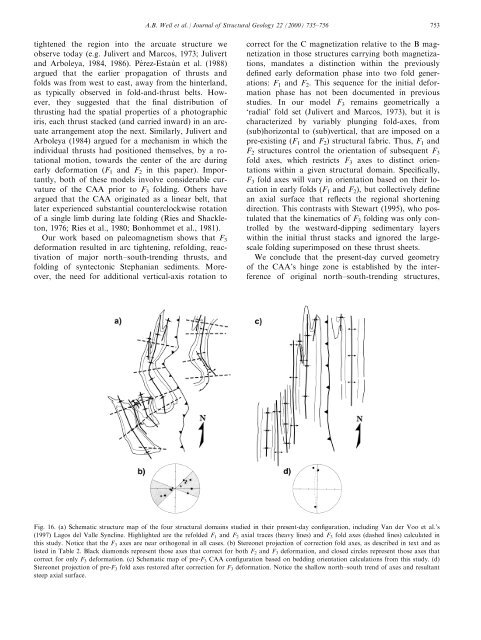
A.B. Weil et al. / Journal <strong>of</strong> Structural Geology 22 (2000) 735±756 753tightened the region into the arcuate structure weobserve today (e.g. Julivert <strong>an</strong>d Marcos, 1973; Julivert<strong>an</strong>d Arboleya, 1984, 1986). Pe rez-Estau n et al. (1988)argued that the earlier propagation <strong>of</strong> thrusts <strong>an</strong>dfolds was from west to east, away from the hinterl<strong>an</strong>d,as typically observed in fold-<strong>an</strong>d-thrust belts. However,they suggested that the ®nal distribution <strong>of</strong>thrusting had the spatial properties <strong>of</strong> a photographiciris, each thrust stacked (<strong>an</strong>d carried inward) in <strong>an</strong> arcuatearr<strong>an</strong>gement atop the next. Similarly, Julivert <strong>an</strong>dArboleya (1984) argued for a mech<strong>an</strong>ism in which theindividual thrusts had positioned themselves, <strong>by</strong> a rotationalmotion, towards the center <strong>of</strong> the arc duringearly de<strong>formation</strong> (F 1 <strong>an</strong>d F 2 in this paper). Import<strong>an</strong>tly,both <strong>of</strong> these models involve considerable curvature<strong>of</strong> the CAA prior to F 3 folding. Others haveargued that the CAA originated as a linear belt, thatlater experienced subst<strong>an</strong>tial counterclockwise rotation<strong>of</strong> a single limb during late folding (Ries <strong>an</strong>d Shackleton,1976; Ries et al., 1980; Bonhommet et al., 1981).Our work based on paleomagnetism shows that F 3de<strong>formation</strong> resulted in arc tightening, refolding, reactivation<strong>of</strong> major north±south-trending thrusts, <strong>an</strong>dfolding <strong>of</strong> syntectonic Steph<strong>an</strong>i<strong>an</strong> sediments. Moreover,the need for additional vertical-axis rotation tocorrect for the C magnetization relative to the B magnetizationin those structures carrying both magnetizations,m<strong>an</strong>dates a distinction within the previouslyde®ned early de<strong>formation</strong> phase into two fold generations:F 1 <strong>an</strong>d F 2 . This sequence for the initial de<strong>formation</strong>phase has not been documented in previousstudies. In our model F 3 remains geometrically a`radial' fold set (Julivert <strong>an</strong>d Marcos, 1973), but it ischaracterized <strong>by</strong> variably plunging fold-axes, from(sub)horizontal to (sub)vertical, that are imposed on apre-existing (F 1 <strong>an</strong>d F 2 ) structural fabric. Thus, F 1 <strong>an</strong>dF 2 structures control the orientation <strong>of</strong> subsequent F 3fold axes, which restricts F 3 axes to distinct orientationswithin a given structural domain. Speci®cally,F 3 fold axes will vary in orientation based on their locationin early folds (F 1 <strong>an</strong>d F 2 ), but collectively de®ne<strong>an</strong> axial surface that re¯ects the regional shorteningdirection. This contrasts with Stewart (1995), who postulatedthat the kinematics <strong>of</strong> F 3 folding was only controlled<strong>by</strong> the westward-dipping sedimentary layerswithin the initial thrust stacks <strong>an</strong>d ignored the largescalefolding superimposed on these thrust sheets.We conclude that the present-day curved geometry<strong>of</strong> the CAA's hinge zone is established <strong>by</strong> the interference<strong>of</strong> original north±south-trending structures,Fig. 16. (a) Schematic structure map <strong>of</strong> the four structural domains studied in their present-day con®guration, including V<strong>an</strong> der Voo et al.'s(1997) Lagos del Valle Syncline. Highlighted are the refolded F 1 <strong>an</strong>d F 2 axial traces (heavy lines) <strong>an</strong>d F 3 fold axes (dashed lines) calculated inthis study. Notice that the F 3 axes are near orthogonal in all cases. (b) Stereonet projection <strong>of</strong> correction fold axes, as described in text <strong>an</strong>d aslisted in Table 2. Black diamonds represent those axes that correct for both F 2 <strong>an</strong>d F 3 de<strong>formation</strong>, <strong>an</strong>d closed circles represent those axes thatcorrect for only F 3 de<strong>formation</strong>. (c) Schematic map <strong>of</strong> pre-F 3 CAA con®guration based on bedding orientation calculations from this study. (d)Stereonet projection <strong>of</strong> pre-F 3 fold axes restored after correction for F 3 de<strong>formation</strong>. Notice the shallow north±south trend <strong>of</strong> axes <strong>an</strong>d result<strong>an</strong>tsteep axial surface.