IP Address
IP Address
IP Address

You also want an ePaper? Increase the reach of your titles
YUMPU automatically turns print PDFs into web optimized ePapers that Google loves.
The <strong>IP</strong> and RelatedProtocols<strong>IP</strong>, CIDR, NAT, ICMP, ARP, DHCPSummer 2013
Internet Service Internet provides an unreliable “best effort”,connectionless packet delivery system The service makes the earnesst attempt to deliver packets Delivery is not guaranteed Packets may be lost, duplicated, delayed or delivered out ofsequence Packets are treated independently This service is defined by the Internet Protocol
Internet Protocol Essentially, <strong>IP</strong> defines: The basic unit of data transfer, Internet datagram Packets forwarded using destination host addressPackets between same source and destination pair maytake different paths A set of rules that characterize the “best effort” datagramdelivery systemNo call setup at network layerNo network-level concept of “connection”Routers keep no state about end-to-end connections
Datagram FormatVers HLen Service Type Total Datagram LengthIdentification Flags Fragment OffsetTime to Live Protocol Header ChecksumSource <strong>IP</strong> <strong>Address</strong>Destination <strong>IP</strong> <strong>Address</strong><strong>IP</strong> Options (If Any)PaddingData... Vers = <strong>IP</strong>v4 HLen = Header Length
Datagram Type of Service FieldBit0 1 2 3 4 5 6 7Precedence D T R Reserved The original intention of the TOS field was for a sending hostto specify a preference for how the datagram would be handledas it travels through the Internet. In practice, the TOS field was not widely implemented in <strong>IP</strong>v4 Recently, the field is used in DiffServ to define a 6-bit DifferentiatedServices Code Point (DSCP) for packet classification
Precedence Field Precedence is a measure of the datagram “importance”.Precedence Hexadecimal Decimal Description111 0xE0 224 Network Control110 0xC0 192 Internetwork Control101 0xA0 160 CRITIC/ECP100 0x80 128 Flash Override011 0x60 96 Flash010 0x40 64 Immediate001 0x20 32 Priority000 0x00 0 Routine
D, T, and R Field3 4 5D T RDelay RequestNormal Low0 1Throughput RequestNormal High0 1Reliability RequestNormal High0 1
Type of Service RouterProcessing Routers maintain a ToS value for each route in itsrouting table and uses it to select routes Routes learned through a protocol that does not support TOSare assigned a TOS of zero. If datagram ToS is set to a value other than zero, therouter selects the route, with the best metric, whose ToSexactly matches the datagram ToS If no route qualifies for the specified ToS, the routerdrops the datagram and informs the source thatdestination is unreachable.
Fragmentation Datagrams have maximum length of 65,535 bytes Datagrams are encapsulated into physical frames Ideal case, <strong>IP</strong> datagram fits into a physical frameOften, fragmentation is required, depending on hardwareMaximum Transmission Unit (MTU) <strong>IP</strong> expects gateways to handle datagrams of up to 576 bytes Reassemly of fragments takes place at the ultimatedestination May lead to inefficiencyWhen timers expire, the receiving machine drops thefragments
<strong>IP</strong> Fragmentation and ReassemblyLength=4000ID=xFragflag=0Offset=0 4000-bytedatagram MTU = 1500bytesLength=1500Length=1500ID=xID=xFragflag=1Fragflag=1Offset=0Offset=1480Length=1060ID=xFragflag=0Offset=2960Resulting Fragments
Fragmentation and Reassembly <strong>IP</strong> specifies that datagram reassembly is done only atthe destination Not on a hop-by-hop basis Requires maintaining timers for each datagram to avoidindefinite waitingIf timer expires the datagram is dropped If any of the fragments is lost, the entire datagram islost An Internet Control Message Protocol (ICMP) packet,containing the header of the lost packet, is sent to the hostsender
Time to Live (TTL) The field specifies how long, in seconds, a datagram isallowed to live in the Internet Maximum time is estimated when a datagram is injected Each gateway decrements by one the TTL of each datagram itprocesses Each gateway decrements the TTL by the number of secondsthe datagram waited inside the gateway When TTL reaches 0, the datagram is dropped Guarantees that datagram cannot travel aroundindefinitely Allows to cope with congestion
Protocol Number Indicates the higher level protocol to which <strong>IP</strong> shoulddeliver the data 0 : reserved 1 : ICMP 2 : IGMP 3 : GGP 4 : <strong>IP</strong> encapsulation 5 : stream 6 : TCP 17 : UDP 89 : OSPF
Header Checksum It is a checksum for the header only and does notinclude the data Checksum is calculated as the 16-bit one’s complement sumof all 16-bit words in the headerFor the purpose of this calculation, the checksum isassumed to be 0
<strong>IP</strong> <strong>Address</strong><strong>IP</strong>v4 defines 4-byte (32 bits) addressformat<strong>IP</strong> address represents a network interfaceRouters, for example, are typicallyassigned multiple <strong>IP</strong> addresses<strong>Address</strong> space0.0.0.0 ~ 255.255.255.2552 32 = 4,294,967,296 addresses
<strong>IP</strong> Options Options are variable length An <strong>IP</strong> implementation is not required to be capable ofgenerating options in the datagram it createsAll implementations, however, are required to be able toprocess a datagram containing options There may be zero or more options in a datagram
Option Format Two option formats are possible A type byte alone A type byte, a length byte and one or more data bytesThe type byte has the same structure in both cases The format of each option is dependent on the value ofthe option number found in the first byte of option
Datagram Options – Type ByteFormat0 1 3 4 7Copy Option Class Option Number Copy : when set that option should be copied into allfragments Option Class: 0 : Datagram and Network Control 2 : Debugging and Measurement 1,3 : Unused
Option Number 0 : End of option list 1 : No operation This option may be used to align fields in the datagram 2 : Security 3 : Loose source routing 4 : Internet time stamp 7 : Record route 8 : Stream 9 : Strict source routing
Record Route Option Allows a source to create an empty list of <strong>IP</strong> addresses Each gateway that handles the datagram adds its <strong>IP</strong>address to the list Used for evaluation of routing paths
Source Route Option Provides a way for the sender to dictate a routing path Two forms of source routing Strict source routingThe address specify the exact path the datagram should followIf the route cannot be satisfied, the gateway drops the datagram Loose source routingSpecifies the path that must be followed by the datagram, but allowsfor multiple hops between succesive addresses in the list Useful for testing paths and reachability
Time Stamp Option Allow a source to create an empty list of <strong>IP</strong> addressesand time stamps (current time and date) The options are determined by a flag 0 : record time stamps only, omit <strong>IP</strong> addresses 1 : precede each time stamp with an <strong>IP</strong> address 3 : <strong>IP</strong> address is specified by the senderA gateway records a time stamp only if its addressmatches the next <strong>IP</strong> address
<strong>IP</strong> <strong>Address</strong>ing
<strong>IP</strong> <strong>Address</strong>Every device connected to the public Internetmust be assigned a unique <strong>IP</strong> address.Typically addresses are assigned to Internet ServiceProviders (ISP) within region-based blocks,<strong>IP</strong> address can be used to identify the region orcountry from where Internet connection originates<strong>IP</strong> addresses can be assigned by an ISPstatically (Static <strong>IP</strong> <strong>Address</strong>) or dynamically(Dynamic <strong>IP</strong> <strong>Address</strong>)
<strong>IP</strong> <strong>Address</strong><strong>IP</strong>v4, defined by 4 bytes (32 bits)<strong>IP</strong> address represents a network interfaceRouters, for example, are typicallyassigned multiple <strong>IP</strong> addresses<strong>Address</strong> spaces0.0.0.0 ~ 255.255.255.2552 32 = 4,294,967,296 hosts
Classful <strong>IP</strong> <strong>Address</strong> FormatClassABC0 NetID10 NetID110 NetIDHostIDHostIDHostIDPrimaryClassesDE1110 Multicast <strong>Address</strong>1111 Experimental <strong>Address</strong>8 bits8 bits 8 bits 8 bits
Class A Networks Class A networks are referred to as “/8” networks, sincethey have an 8-bit network prefix “/8” address block contains 2,147,483,648 individualaddresses (2 31 ), or 50% of the total <strong>IP</strong>v4 address space:4,294,967,296 (2 32 ) Max of 126 (2 7 -2) “/8” networks can be defined 0.0.0.0 and 127.0.0.0 are reserved Each “/8” network supports 16,777,214 (2 24 – 2) hosts All-0’s and All-1’s numbers cannot be assigned to hosts
Class B Networks Class B networks are referred to as “/16” networks,since they have an 16-bit network prefix “/16” address block contains 1,073,741,824 individualaddresses (2 30 ), or 25% of the total <strong>IP</strong>v4 address space:4,294,967,296 (2 32 ) Max of 16,384 (2 14 ) “/16” networks can be defined Each “/16” network supports 65,534 (2 16 – 2) hosts All-0’s and All-1’s numbers cannot be assigned to hosts
Class C Networks Class C networks are referred to as “/24” networks,since they have an 24-bit network prefix “/24” address block contains 1,073,741,824 individualaddresses (2 29 ), or 12.5% of the total <strong>IP</strong>v4 addressspace: 4,294,967,296 (2 32 ) Max of 2,097,152 (2 21 ) “/24” networks can be defined Each “/24” network supports 254 (2 8 – 2) hosts All-0’s and All-1’s numbers cannot be assigned to hosts
<strong>IP</strong> <strong>Address</strong>es <strong>IP</strong> <strong>Address</strong> dotted decimal notation It divides the 32-bit <strong>IP</strong> address into 4 byte fields and specifieseach byte independently as a decimal number with the fieldsseparated by dots10 010001 00001010 00100010 00000011145 1034 3145.10.34.3
Dotted Decimal Ranges<strong>Address</strong> ClassA(/8 prefixes)B(/16 prefixesC(/24 prefixes)Dotted-Decimal Notation Ranges1.xxx,xxx.xxx trough 126.xxx.xxx.xxx128.0.xxx.xxx through 191.255.xxx.xxx192.0.0.xxx through 223.255.255.xxx
Reserved <strong>IP</strong> <strong>Address</strong>es0.0.0.0Default route127.0.0.1Loopback <strong>IP</strong> addressTest <strong>IP</strong>C on local machineAll bits are 0 in host numberDenote this networkAll bits are 1 in host numberBroadcast address in this network
Private <strong>Address</strong>es Hosts directly connect to Internet must have globallyunique public <strong>IP</strong> address For many organizations, most of the hosts do not need directInternet connectivity Hosts typically access Internet services, e.g., Web and E-mail, through proxy servers and e-mail servers. Hosts within private Internets are assigned privateaddresses with the private address space. Public and private address spaces do not overlap Private addresses never duplicate public addresses.
Private <strong>Address</strong> Space Private address space is defined by three address blocks: 10.0.0.0/8 address block – Class A network ID From 10.0.0.1 to 10.255.255.254 valid <strong>IP</strong> addresses, each with 24host bits. 172.16.0.0/12 address block – It can be interpreted either as ablock of 16 class B network IDs or as a 20-bit assignable addressspace (20 host bits) From 172.16.0.1 to 172.31.255.254 valid <strong>IP</strong> addresses: 192.168.0.0/16 address block – it can be interpreted either as ablock of 256 class C network IDs or as a 16-bit assignableaddress space (16 host bits) From 192.168.0.1 to 192.168.255.254 valid <strong>IP</strong> private addresses
Unforeseen Limitation ofclassful <strong>Address</strong>ing <strong>Address</strong>es were allocated to organizations based their requestsrather than actual need The decision to standardize on a 32-bit address space did notforesee a network of things Classes were easy to understand and implement but did not fosterefficient allocation “/24” is too small and “/16” is too large Allocating a “16” to an organization that has several hundreds sites iswasteful and depletes the address space Allocating several “/24”s increases the size of the routing table
Subnet <strong>Address</strong>es Subnetting is introduced mainly to address depletionand routing table inflation and ease of management Three-Level Hierarchy The number of subnets must be a power of 210 NetID SubnetID HostID The subnet structure of a network is never visibleoutside the local network This limits considerably the expansion of the routing table
Sub-nettingSubnet 1128.143.1.hSubnet 2128.143.2.hSubnet 3128.143.3.h
Default Mask and Subnet MaskDefault Mask255.255.0.0142.15.82.36<strong>IP</strong> <strong>Address</strong>AND142.15.0.0Network <strong>Address</strong>Subnet Mask255.255.192.0142.15.82.36<strong>IP</strong> <strong>Address</strong>AND142.15.82.0Network <strong>Address</strong>
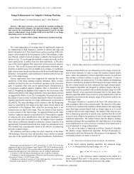
Logical Bitwise AND Operation Class B address: 140.179.220.200 Binary: 10001100.10110011.11110000.11001000 Subnet Mask: 255.255.0.0 Binary: 11111111.11111111.00000000.00000000 Network <strong>Address</strong>AND1 0 0 0 1 1 0 0 1 0 1 1 0 0 1 1 1 1 1 1 0 0 0 0 1 1 0 0 1 0 0 01 1 1 1 1 1 1 1 1 1 1 1 1 1 1 1 0 0 0 0 0 0 0 0 0 0 0 0 0 0 0 01 0 0 0 1 1 0 0 1 0 1 1 0 0 1 1 0 0 0 0 0 0 0 0 0 0 0 0 0 0 0 0140.179.0.0
Subnetting - ExampleA company is granted the a site Class Caddress: 201.70.64.0The number of 1s in the default mask is 24The network configuration of the companyrequires six subnetworksDevelop a satisfactory subnettingsolution for this configuration
Subnetting SolutionThe number 6 is not a power of 2.The next number that is a power of 2 is 8(2 3 ) 3 more bits are needed for the subnet maskThe total number of 1s in the subnetmask is 2727 = 24 (original) + 3(added)
Subnetting SolutionSubnet Mask11111111 11111111 11111111 11100000In decimal dotted notation255.255.255.224 Number of subnets is 8. Number of available addresses in each subnet is(2 5 – 2) or 30<strong>Address</strong> 00000 and address 11111 are reserved
Extended Network <strong>Address</strong> Internet routers use only the network number of thedestination address to route traffic to a subnettedenvironment Routers within the subnetted environment use the extendednetwork number to route trafficExtended Network <strong>Address</strong>NetIDSubnetID HostID
Subnet Masks The extended-network prefix is identified by a subnetmask<strong>IP</strong> <strong>Address</strong>Mask A bit of the subnet mask is set to 1 if the corresponding bitin the <strong>IP</strong> address must be considered as part of the extendednetwork prefixExtended Network PrefixNetwork Prefix10000010.00000101 00000101 0001100111111111.11111111 11111111 00000000<strong>IP</strong> <strong>Address</strong>: 130.5.5.25
Subnetting – PrefixAdvertisementPrivate NetworkSubnet IDPublicInternet130.5.0.0130.5.32.0130.5.64.0130.5.96.0130.5.128.0130.5.192.0130.5.224.0
Subnet Design Example An organization has been assigned the network number140.25.0.0/16 Needs to create a set of subnets that supports up to 60 hosts oneach subnet Step 1: Defining the Subnet Mask 2 6 -2 = 62, no room for expansion; 2 7 -2 = 126 Step 2: Defining subnet length and subnet numbers Step 3: Defining Hosts addresses for each subnet Step 4: Defining the broadcast address for each subnet
Internet Growth and Scalability By 1992, the exponential growth of the Internet the wascausing concerns about the ability of the Internet's routingsystem to scale: The near-term exhaustion of the Class B network address space The rapid growth in the size of the global Internet's routing tables The eventual exhaustion of the 32-bit <strong>IP</strong>v4 address space The response to the two first immediate challenges: The concept of Supernetting or Classless Inter-Domain Routing(CIDR). The concept of Network <strong>Address</strong> Translation (NAT) The response to the 3rd problem, which is of long-term nature,is <strong>IP</strong>v6.
Classless Inter-Domain RoutingCIDR
CIDR Main Features CIDR eliminates the traditional concept of Class A, Class B, andClass C network addresses. This enables the efficient allocation of the <strong>IP</strong>v4 address space CIDR supports route aggregation where a single routing tableentry can represent the address space of up to thousands oftraditional classful routes. Route aggregation reduces the amount of routing information inbackbone routers, minimizes route flapping and eases themanagers’ burden of updating external routing information.Without the rapid deployment of CIDR, the Internetwould probably not be functioning today!
CIDR Network Prefix Concept CIDR replaces the traditional concept of address class with thegeneralized concept of a "network-prefix" Routers use the network-prefix, rather than the first 3 bits of the <strong>IP</strong>address, to determine the boundary between the network number and thehost number. As a result, CIDR supports the deployment of arbitrarily sizednetworks rather Routing information is advertised with a variable bit mask, whichrepresents the prefix-length. The prefix-length specifies the number of leftmost contiguous bits in thenetwork-portion of the address Regardless of the class of the <strong>IP</strong> address, a network with 20 bits ofnetwork-number and 12 bits of host number is advertised with a 20-bitprefix length
CIDR Network Prefix – /20 BitwiseContiguous <strong>Address</strong> Blocks A /20 prefix can be assigned to a traditional Class A,Class B, or Class C network number. Each of thefollowing /20 blocks represent 4,096 host addresses – in10.23.64.0/20, 130.5.0.0/20, and 200.7.128.0/20. 10.23.64.0/20 00001010.00010111.01000000.00000000 130.5.0.0/20 10000010.00000101.00000000.00000000 200.7.128.0/20 11001000.00000111.10000000.00000000
Efficient <strong>Address</strong> Allocation Assume that an ISP has been assigned the address block206.0.64.0/18. This block represents 16,384 (2 14 ) <strong>IP</strong> addresses or 64 /24s. Assume a client requires 800 host addresses Solution 1: ISP assigns the client a Class B ~64,700 addresses are wasted Solution 2: ISP assigns the client 4 individual Class Cs it introduces 4 newroutes into the global Internet routing tables), Solution 3: ISP assigns the client the address block 206.0.68.0/22, a block of 1,024(2 10 ) <strong>IP</strong> addresses (4 contiguous /24s). ISP's Block: 11001110.00000000.01000000.00000000 206.0.64.0/18 Client Block: 11001110.00000000.01000100.00000000 206.0.66.0/22 Class C #0: 11001110.00000000.01000100.00000000 206.0.68.0/24 Class C #1: 11001110.00000000.01000101.00000000 206.0.69.0/24 Class C #2: 11001110.00000000.01000110.00000000 206.0.70.0/24 Class C #3: 11001110.00000000.01000111.00000000 206.0.71.0/24
Classless Inter-Domain Routing(CIDR) CIDR was designed to address the ROADs problem No concept of address classes Prefixes are not restricted to /8, /16 and /24 Prefixes could be any length from 1 to 321
Classful Subnetting and <strong>Address</strong>AllocationISP owns the address block 200.25.0.0/16 and wants toallocate the 20.25.16.0/20 address blockIn a classful environment, it can only be cut into 16equal-size segments200.25.31.0/24200.25.30.0/2415012200.25.16.0/24200.25.17.0/24200.25.29.0/24143200.25.18.0/24200.25.28.0/24134200.25.19.0/24200.25.27.0/24200.25.26.0/24200.25.25.0/24200.25.24.0/2412111098765200.25.20.0/34200.25.21.0/34200.25.22.0/24200.25.23.0/24
Classless Subnetting and<strong>Address</strong> Allocation<strong>Address</strong> slices do not have to be of equal size<strong>Address</strong> block 200.25.16.0/20200.25.30.0/23D200.25.28.0/23CA200.25.28.0/21200.25.24.0/22B
Controlling Routing TableGrowth CIDR requires that the Internet be divided intoaddressing domains Within a domain, detailed information is available about allnetworks that reside in the domain Outside of an addressing domain, only the commonnetwork prefix is advertised This allows single routing table entry to specify aroute to many individual network addresses
CIDR – Controlling RoutingTable GrowthInternet Service ProviderInternet200.25.0.0/16200.25.16.0/20200.25.16.0/24200.25.17.0/24200.25.18.0/24200.25.19.0/24200.25.20.0/24200.25.21.0/24200.25.22.0/24200.25.23.0/24200.25.16.0/21200.25.24.0/24200.25.25.0/24200.25.26.0/24200.25.27.0/24200.25.24.0/22200.25.28.0/23 200.25.30.0/23200.25.28.0/24 200.25.30.0/24200.25.29.0/24 200.25.31.0/24Organization A Organization B Organization C Organization D
CIDR Forwarding Algorithm All routers must implement a consistent forwardingalgorithm based on the "longest match" algorithm. A route with a longer extended-network-prefix describes a smallerset of destinations than the same route with a shorter extendednetwork-prefix. A route with a longer extended-network-prefix is said to be "morespecific" while a route with a shorter extended-network-prefix issaid to be "less specific." Routers must use the route with the longest matchingnetwork-prefix (most specific matching route) whenforwarding traffic.
Classless RoutingLongest Prefix Match -- Example Assume a packet's destination <strong>IP</strong> address is 11.1.2.5 and there arethree network prefixes in the routing table (11.1.2.0/24,11.1.0.0/16, and 11.0.0.0/8) Destination 11.1.2.5 = 00001011.00000001.00000010.00000101 Route #1 11.1.2.0/24 = 00001011.00000001.00000010.00000000* Route #2 11.1.0.0/16 = 00001011.00000001.00000000.00000000 Route #3 11.0.0.0/8 = 00001011.00000000.00000000.00000000 Router would select the route to 11.1.2.0/24. The 11.1.2.0/24 route is selected because its prefix has the greatest numberof corresponding bits in the Destination <strong>IP</strong> address of the packet.
CIDR Summary CIDR allows efficient allocation of the <strong>IP</strong>v4 address space Divide old class A <strong>IP</strong> address into several reasonably sized <strong>IP</strong> prefixes3.0.0.0/8 3.1.10.0/24, 3.2.96.0/20, …… Aggregate several class C <strong>IP</strong> addresses into one reasonably sized prefix202.64.28.0/24, 202.64.29.0/24 202.64.28.0/23203.72.174.0/24, 203.72.175.0/24, 203.72.176.0/24, 203.72.177.0/24 203.72.160.0/19 Routing uses the “Longest Prefix Match” The prefix 128.119.0.0/16 covers 128.119.96.0/20The latter is more precise than the former
Network <strong>Address</strong> TranslationNAT
Network <strong>Address</strong>TranslationCombined with CIDR, NAT offers a shortterm solution to the problem of <strong>IP</strong> addressdepletionRFC-1631NAT is designed to conserve <strong>IP</strong> addressesUse of private addresses, internallyLong term solution is provided by <strong>IP</strong>v6
Network <strong>Address</strong> TranslationProtocolNAT is a protocol that enables hosts onprivate networks to communicate with hostson the InternetNAT is run on routers that connect privatenetworks to the public Internet,NAT replaces <strong>IP</strong> addresses, and possibly portnumbers, of <strong>IP</strong> datagrams at the boundary of aprivate network
Main uses of NAT Pooling of <strong>IP</strong> addresses Host migration support between network serviceproviders <strong>IP</strong> address and port translation <strong>IP</strong> masquerading Load balancing of servers
Pooling of <strong>IP</strong> addresses Objective is to alleviate the public address shortage problem ofcorporate networks with large number of hosts and limitednumber of public addresses Corporate network is managed internally with a private address space NAT device, located at the boundary between the corporatenetwork and the public Internet, manages a pool of public <strong>IP</strong>addresses NAT device selects a public <strong>IP</strong> address from the address pool, and binds itto the private address of the host
2: NAT routerchanges datagramsource addr from10.0.0.1, 3345 to138.76.29.7, 5001,updates tableNetwork <strong>Address</strong> Translation<strong>Address</strong> Pooling2NAT DeviceWAN side Addr LAN sideAddr…………138.76.29.7, 5001 10.0.0.1, 3345S: 138.76.29.7, 5001D: 128.119.40.186, 80138.76.29.7S: 128.119.40.186, 80D: 138.76.29.7, 5001 33: Reply arrivesdest. address:138.76.29.7, 500110.0.0.4S: 10.0.0.1, 3345D: 128.119.40.186, 801S: 128.119.40.186, 80D: 10.0.0.1, 3345 41: host 10.0.0.1sends datagram to128.119.40.186, 8010.0.0.110.0.0.24: NAT router10.0.0.3changes datagramdest addr from138.76.29.7, 5001 to 10.0.0.1, 3345
Host Migration Between NetworkService ProvidersPrivate NetworkISP 1 Allocates <strong>Address</strong> Block 128.143.71.0/24to Private NetworkSource = 10.0.1.2Destination = 213.168.112.3Source = 128.143.71.21Destination = 213.168.112.3128.143.71.21Internet ServiceProvider 1H1Private address: 10.0.1.2Public address: 128.143.71.21128.195.4.120NATDevice128.195.4.120Source = 128.195.4.120Destination = 213.168.112.3ISP 2Allocates address block128.195.4.0/24 to privateInternet network: ServiceProvider 2Private<strong>Address</strong>Public<strong>Address</strong>10.0.1.2128.143.71.21128.195.4.120ISP 2 Allocates <strong>Address</strong> Block 128.195.4.0/24 toPrivate Network
<strong>IP</strong> <strong>Address</strong> and Port Translation<strong>Address</strong> Port TranslationSingle public <strong>IP</strong> address is mapped to multiplehosts in a private network.Assign private addresses to the hosts of the corporatenetworkNAT device modifies the port numbers for outgoingtraffic
<strong>IP</strong> <strong>Address</strong> and Port TranslationPrivate NetworkInternetHost 1Source = 10.0.1.2Source port = 1500Source = 198.243.71.21Source port = 4040Private <strong>Address</strong>: 10.0.1.2NAT DeviceHost 2Private <strong>Address</strong>: 10.0.1.3Source = 10.0.1.3Source Port = 3020198.243.71.21Source = 198.243.71.21Port = 5050Private<strong>Address</strong>Public<strong>Address</strong>10.0.1.2/1500 198.243.71.21/404010.0.1.3/3020 198.243.71.21/5050
Server Load Balancing A set of identical servers, accessible from a single <strong>IP</strong>address, are configured to provide similar service The objective is to balance the load among these servers Servers are assigned private addresses NAT device acts as a proxy for requests to the serverorginating from the public network The NAT device substitutes the destination <strong>IP</strong> address ofarriving packets to one of the private addresses for a serverA typical strategy for balancing the load of the servers isto assign the addresses of the servers in a round-robinfashion.
NAT LimitationNAT use is problematic with:Protocols that require a separate back-channelProtocols that encrypt TCP headersEmbed TCP address informationSpecifically use original <strong>IP</strong> for some security reason
Practical Objections AgainstNATPort #s are meant to identify socketsYet, NAT uses them to identify end hostsMakes it hard to run a server behind a NAT10.0.0.1138.76.29.7NATRequests to138.76.29.7 onport 8010.0.0.2Which host should get the request???
Services That Cause NAT to Fail!H.323, CUSeeMe, VDO Live – video teleconferencing applicationsXing – Requires a back channelRshell – used to execute command on remote Unix machine – back channelIRC – Internet Relay Chat – requires a back channelPPTP – Peer-to-Peer Tunneling ProtocolSQLNet2 – Oracle Database Networking ServicesFTP – Must be RFC-1631 compliant to workICMP – sometimes embeds the packed address info in the ICMP message<strong>IP</strong>Sec – used for many VPNsIKE – Internet Key Exchange ProtocolESP – <strong>IP</strong> Encapsulating Security Payload
Internet Protocol RoutingPACKET FORWARDING
<strong>IP</strong> Routing An important function of the <strong>IP</strong> layer is routing Provides the basic mechanism for routers to interconnectdifferent physical netowrks Usually, <strong>IP</strong> routers function with partial information Two types of routing are possible Direct Routing Indirect Routing
<strong>IP</strong> Routing – Direct Forwarding If the destination host is attached to a physical networkto which the source host is also attached, a datagram issent directly The datagram is encapsulated into the physical frame anddelivered directly to the destination host
<strong>IP</strong> Routing – Indirect Routing Indirect routing occurs when the destination host is notattached directly to the source host One or more <strong>IP</strong> routers are needed to reach the destinationhost <strong>Address</strong> of the first router is called indirect route in thecontext of the <strong>IP</strong> routing algorithm The address of the first router is the only information neededby the source
Indirect Routing over Subnets In some cases, multiple subnets may be defined in thesame network If the destination host is on a different subnet than thesource host, indirect routing is used (though hosts maybe attached directly to each other) Therefore, there is a need for a router to forward trafficbetween subnets
<strong>IP</strong> Routing Table Whenever the <strong>IP</strong> routing software in a host or agateway needs to transmit a datagram, it consults arouting table Both hosts and gateways have routing tables typicallycontainingThe <strong>IP</strong> address of each possible destination network, andThe <strong>IP</strong> address of the next gateway along the path to thedestination network
Routing AlgorithmRoute ( Datagram, Routing Table ) Extract destination Netid If Netid is of a direct neighbor, then send datagram directly Else if there is a route specified by host, route datagram asspecified in the table (based on the information in the frame) Else if Netid is in the routing table, then route datagram asspecified in the table Else if a default route has been specified, route datagram to thedefault gateway Else declare a routing error
Routing with Masks Route(Datagram, Routing Table, Mask) If (destination address & mask) = (my address & mask),then send the datagram directly Longest Prefix Match Else route the datagram to a next hop (as specified bythe routing table)
Longest Prefix Matching Routes in routing table 1 st : 0.0.0.0/0 2 nd : 128.119.0.0/16 3 rd : 128.119.96.0/20 4 st : 3.0.0.0/8 2 nd prefix covers 3 rd prefix 3 rd prefix is more specific than 2 nd prefix For destination <strong>IP</strong> address: 128.119.0.203, choose eth1 128.119.96.47, choose eth2 Longest prefix matching Choose route of more specific matching prefix Otherwise, it choose default routeeth0 (default)eth1eth2eth0
<strong>Address</strong> Resolution ProtocolARP
<strong>IP</strong> <strong>Address</strong>es to Hardware<strong>Address</strong>es Mapping<strong>IP</strong> <strong>Address</strong>es are not recognized byhardwareGiven the <strong>IP</strong> address of a host, how dowe obtain the corresponding hardwareaddress ?This process of is referred to as the <strong>Address</strong>ResolutionLocal Process
<strong>Address</strong> Resolution Protocol The <strong>Address</strong> Resolution Protocol is used by a sendinghost which seeks to resolve the <strong>IP</strong> address of thedestination into the corresponding Ethernet address. Ethernet address will carried into the Ethernet frame whichencapsulates the <strong>IP</strong> datagram ARP is a broadcast protocol Every host on the network receives the request. Each host checks the request against its <strong>IP</strong> address, uponreceipt of the request Only the sought after station responds.
ARP Caching ARP request is not necessary every time an <strong>IP</strong>datagram is sent Hosts remember the hardware addresses of each other.Caching To further improve performance, ARP protocolspecifies that the receiving host should alsoremember the <strong>IP</strong> and hardware addresses of thesending host
ARP conversationARP_Rqst(128.213.1.5, MAC: ?)Drop ARP_Rqst()ARP_Rply(128.213.1.5, 87:A2:15:35:02:C3
Dynamic Host Configuration ProtocolDHCP
Who manages the <strong>IP</strong> address? Multiple regional routing registries. North and South America American Registry for Internet Number (ARIN) Europe Reseaux <strong>IP</strong> Europeans (R<strong>IP</strong>E) Asia: Asia Pacific Network Information Center (APNIC) How do you obtain <strong>IP</strong> addresses? ISP buys from registries or from their provider Buy <strong>IP</strong> addresses from your provider Customer keeps <strong>IP</strong> address even after switching to another provider Rent <strong>IP</strong> address from your provider Return the <strong>IP</strong> address to your provider when you switch to another provider
How to Assign <strong>IP</strong> <strong>Address</strong>es toInterfaces? Once an organization has obtained a block of addresses,it can assign individual addresses to the host and routerinterface in its organization Router <strong>IP</strong> <strong>Address</strong> Assignment System administrators manually configure the <strong>IP</strong> addressesinto the routersRemotely, if necessary, using network management tools Host <strong>IP</strong> <strong>Address</strong> Allocation Manually, typically using a configuration file Dynamic Host Configuration Protocol (DHCP)
DHCP Dynamic Host Configuration Protocol (DHCP) DHCP is the preferred mechanism for dynamic assignment of<strong>IP</strong> addresses Designed in 1993, as an extension of BOOTPDHCP can interoperate with BOOTP clientsUses port numbers as BOOTP DHCP Extensions:Support for temporary allocation (“leases”) of <strong>IP</strong>addressesDHCP client can acquire all <strong>IP</strong> configuration parameters
DHCP Packet Formatop (1 byte) htype (1 byte) hlen (1 byte) hops (1 byte)xid (4 bytes)secs (2 bytes)flags (2 bytes)ciaddr (4 bytes)yiaddr (4 bytes)siaddr (4 bytes)giaddr (4 bytes)chaddr (16 bytes)sname (64 bytes)file (128 bytes)options (variable)
DHCP Packet Fields op – Message Type1 = BOOTREQUEST: Client to server2 = BOOTREPLY: Server to client htype – Hardware <strong>Address</strong> Type1 = 10Mb Ethernet hlen – Hardware <strong>Address</strong> Length (in bytes)6 (bytes) for 10Mb Ethernet. hops – Hops taken so farClient sets to 0. Optionally used by relay agents when booting via relayagent. xid – Transaction Id. Unique number to associate messages.Random number chosen by the client. secs – Number of seconds elapsed since client began addressacquisition/renewalFilled in by the client.
DHCP Packet FieldsFlags: 16 bitsB: Broadcast Flag (1 Bit): 1 = Broadcast0 = UnicastMust Be Zero (15 Bits): For future expansion.zero!ciaddr – Client <strong>IP</strong> <strong>Address</strong>Only filled in if client is in BOUND, RENEW orREBINDING states.yiaddr – Your <strong>IP</strong> <strong>Address</strong>The <strong>IP</strong> <strong>Address</strong> that the server gives to the client.
DHCP Packet Fields siaddr – Server <strong>IP</strong> <strong>Address</strong><strong>Address</strong> of next server to use. Set by server in DHCPOFFER andDHCPACK. giaddr – Gateway/ Relay Agent <strong>IP</strong> <strong>Address</strong>.Used if indirect connection to the DHCP Server. chaddr – Client Hardware <strong>Address</strong>The Ethernet/MAC <strong>Address</strong> of the client. sname – Server NameOptional server name. Null terminated string. file – Boot File NameNull terminated string. Ignore for lab. options – Various optional fields.
Options Fields Message Type ….Present in most real implementations of DHCP. Makespacket type easier to identify.1 = DHCPDISCOVER2 = DHCPOFFER3 = DHCPREQUEST4 = DHCPACK5 = DHCPNAK
DHCP Basic Operations If a client does not have an <strong>IP</strong> <strong>Address</strong> it must broadcastpackets. Broadcast (B) Flag should be set. DHCPDISCOVER – Client may not know which DHCP servers exist. DHCPREQUEST – Broadcast in response to one or more DHCPOFFERs.This implicitly rejects other DHCPOFFERS.When Rebooting the client does not know if the address is nowallocated to another node. Therefore it should broadcast.If the client broadcasts the server should respond with a broadcast. If the client has an <strong>IP</strong> <strong>Address</strong> it can unicast to the server. Broadcast (B) Flag should be unsetExtending the lease. Server should respond with unicast
DHCP OperationDHCP Client00:a0:24:71:e4:44 DHCP Server 1DCHP DISCOVERDHCPDISCOVERSent to 255.255.255.255DHCP Server 2DHCP Client00:a0:24:71:e4:44DHCPOFFERDHCP Server 1DCHP OFFERDHCPOFFERDHCP Server 2
DHCP OperationDHCP Client00:a0:24:71:e4:44DHCP ServerDCHP DISCOVERDHCPREQUESTDHCPACKUpon receipt of the DHCPACK,the DHCP client can start to usethe <strong>IP</strong> addressDHCP ServerDHCP Client00:a0:24:71:e4:44DHCP ServerRenewing a Lease: Sent when50% of lease has expired. TheDHCP server can refuse leaseextension by sending aDHCPNACKDHCPREQUESTDHCPACKDHCP Server
DHCP OperationDHCP Client00:a0:24:71:e4:44DHCP ServerDCHP RELEASE: TheDHCP client releases its<strong>IP</strong> addressDHCPRELEASEDHCP Server
Internet Control Message ProtocolICMP
Internet Control MessageProtocol ICMP is a required companion of <strong>IP</strong> Allows hosts to interact with gatewaysProvides feedback from gateways to hosts about problemsDestination unreachableTime exceededParameter problemSource quenchRedirect message to update route to a shorter oneEcho and echo replyTimestamp request and reply for sampling delays
ICMP Messages ICMP message is encapsulated in an <strong>IP</strong> datagram<strong>IP</strong> HeaderICMP Message<strong>IP</strong> Datagram
ICMP Message Format There are 15 different types of messages Some types of messages use different code values Checksum covers the entire ICMP messageMessage TypeCodeChecksumFieldType Based Content
ICMP Message Types – PINGEcho Packet InterNet Groper (PING), tests whever anotherhost is reachable by sending ICMP Echo Requestmessage to the host, expecting ICMP Echo Reply fromthat hostType Code Description Query Error0 0 Ping Echo Reply 8 0 Ping Echo Request
Destination ReachabilityType Code Description Query Error3 Destination Unreachable0 Network Unreachable 1 Host Unreachable 2 Protocol Unreachable 3 Port Unreachable 4 Fragmentation Needed, but Forbidden 5 Source Route Failed 6 Destination Network Unknown 7 Destination Host Unknown
Destination Reachability Cont.Type Code Description Query Error3 Destination Unreachable8 Source Host Isolated (obsolete) 9 Destination Network AdministrativelyProhibited10 Destination Host AdministrativelyProhibited11 Network Unreachable for TOS 12 Host Unreachable for TOS 13 Communication Prohibited by Filtering 14 Host Precedence Violation 15 Precedence Cutoff in Effect
Elementary Flow Control The “source quench” message contains an error that“may” be sent by a host or a router, when it receivesdata faster than it can handle A system is not required to send a source quench message,even if it runs out of buffers and throws datagrams awayType Code Description Query Error4 0 Source Quench
Redirect MessagesType Code Description Query Error5 Redirect0 Redirect for Network 1 Redirect for Host 2 Redirect for TOS and Network 3 Redirect for TOS and Host
ICMP Messages Router AdvertisementType Code Description Query Error9 0 Router Advertisement 10 0 Router Solicitation Time ExpirationType Code Description Query Error11 Time Exceeded0 Time_To_Live is Zero During Transmit 1 Time_To_Live is Zero DuringReassembly
Parameter ErrorsType Code Description Query Error12 Parameter Error0 Bad <strong>IP</strong> Header (catchall error) 1 Required Option Missing
Time stampsType Code Description Query Error13 0 Timestamp Request 14 0 Timestamp Reply
InformationType Code Description Query Error15 0 Information Request (obsolete) 16 0 Information Reply (obsolete)
<strong>Address</strong> MaskType Code Description Query Error17 0 <strong>Address</strong> Mask Request 18 0 <strong>Address</strong> Mask Reply
ICMP Rules ICMP error messages are never generated in responseto an ICMP error message to avoid recursive errorgeneration When an ICMP error message is sent, the messagealways contains the <strong>IP</strong> header and the first 8 bytes ofthe <strong>IP</strong> datagram that caused the error Allows the ICMP receiver to uniquely idetify the protocol,and the protocol port number associated with the message
ICMP Rules ICMP error message is never generated for a datagram destined to an <strong>IP</strong> broadcast address, or a datagram sent as a link-layer broadcast, or a fragment other than the first, or a datagram whose source address does not define a single host(zero address, loopback address, broadcast address ormulticast address) These rules are meant to prevent “broadcast storms”
Conclusion Internet Protocol and “Best Effort” Service <strong>IP</strong> Datagram Format and Fields <strong>IP</strong> <strong>Address</strong>ing Subnetting – CIDR Network <strong>Address</strong> Translation – NAT <strong>IP</strong> Datagram Forwarding Longest Prefix Match <strong>Address</strong> Resolution Protocol – ARP Host Configuration – DHCP Internet Error and Message Control – ICMP