
You also want an ePaper? Increase the reach of your titles
YUMPU automatically turns print PDFs into web optimized ePapers that Google loves.
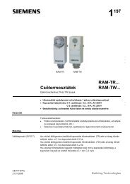
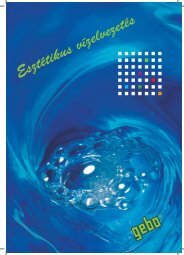
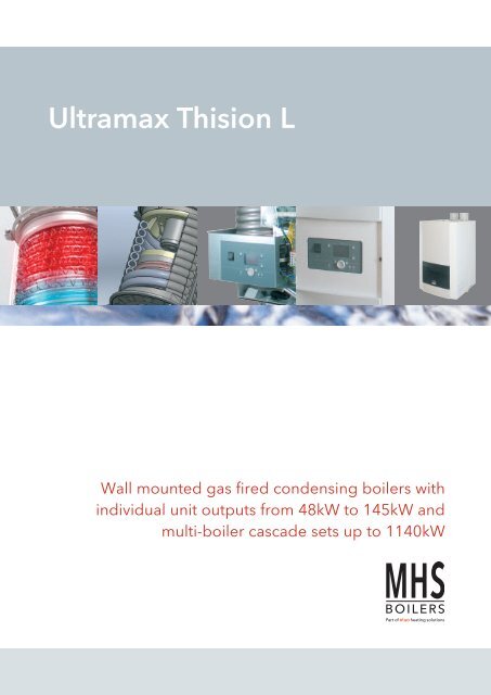
<strong>Ultramax</strong> <strong>Thision</strong> LWall mounted gas fired condensing boilers withindividual unit outputs from 48kW to 145kW andmulti-boiler cascade sets up to 1140kW
Dependable performance andlifelong high efficiencyThe <strong>Thision</strong> L is the latest addition to the popular and extremely well regarded<strong>Ultramax</strong> family of boilers from MHS Boilers, and sets new benchmarks inreliability, performance and design features.Utilising a new state-of-the-art double helixfinned tube heat exchanger design, which isthe product of extensive research,development and field testing, the <strong>Ultramax</strong><strong>Thision</strong> L wall mounted appliances setnew standards in gas fired condensingboiler design.The cool flame, low emission premix burnersystem accords extremely low NOx, whilstthe all stainless steel construction heatexchanger returns a long and reliableservice life of non-fading top level efficiency.The water ways of the unique design heatexchanger consists of a pair stainless steelfinned tubes arranged in a vertical doublehelix and affords low hydraulic resistance.The 1:6 modulation ratio of the burnercontrol system in the <strong>Thision</strong> L allowsoptimum seasonal efficiency through itsability to closely follow changes in load,whilst environmental impact is kept to aminimum through NOx emission of less than39mg/kWh @ 0% O² (which adequatelyexceeds the requirements for the highestBREEAM credits). Another standard featureis the option to utilise room sealed or openflue systems.The <strong>Ultramax</strong> <strong>Thision</strong> L boilers are suitable foruse in single boiler or multiple/cascadeinstallations and a range of cascade systemaccessories is available for arrangements oftwo to eight boilers with output up to a classleading 1140kW.2
Put your mind at restIt’s easy to ignore your boiler and heating system - until it goes wrong orbreaks down. A system failure, especially one caused by lack of maintenance,can be inconvenient and costly.It isn’t hard to imagine thedifficulties that problems withyour heating system can cause.And in some situations lack ofheating and hot water can becritical. Similar to your car, aregularly maintained heatingsystem will run more efficientlyand any potential problems canbe resolved before they developinto major system failure.Financially, planned maintenancemakes sense too. It avoids majorcapital outlay and the associatedcosts of system down time - plus itcan keep your fuel costs down aswell as ensuring you areminimising your emissions.At MHS Boilers we provide amaintenance and service solutionfor your boiler - enabling you torest safe in the knowledge thatwe’ll take care of it.Go to www.mhsboilers.com anddownload or request a copy ofour Maintenance and ServiceSolutions brochure.Please contact our servicedepartment and we will bedelighted to arrange a quotation:Tel : 01268 546770 or e-mail:service@mhsboilers.co.ukOur highly skilledand trainedservice andtechnical supportengineers areonly a phonecall away3
FeaturesQualityExceptional high quality & unequalled lifetime highefficiency through the use of corrosion resistant stainlesssteel as a heat exchanger material.Compact dimensionsMindful that space is at a premium in commercialbuildings, the <strong>Thision</strong> L delivers high power from minimalspace requirements.Controls optionsThe <strong>Ultramax</strong> <strong>Thision</strong> L series boilers may be installed assingle appliances or in cascade/ multiple boilerarrangements of up to 16 appliances. Time andtemperature control over a hot water cylinder and heatingzones is easily possible via the use of optional additionalcontrol components. Up to eight heating circuits, eitherconstant flow or with VT mixing valves may controlled inconjunction with a single boiler or a cascadearrangement. It is also possible to use either constantspeed boiler primary pumps or with the inclusion of anoptional interface, modulating speed pump/s may becontrolled leading to enhanced boiler operationalefficiency and reduced pump electricity consumption.See page 8 for details.Extreme efficiencyAn all stainless steel heat exchanger coupled with amodulating radiant premix burner with turndown to 16%of maximum output, the <strong>Thision</strong> L boilers can returnannual efficiency >110% net. The working principle of theheat exchanger is “cross-flow” where the water flows in anupward direction and the flue gasses flow downward, andwith this operation, the most efficient combustion resultsare obtained.Low hydraulic resistanceUtilising an arrangement of generous bore, twin watertubes in helical fashion, the pressure loss of the heatexchanger is extremely low for an appliance of its typewhich avoids the need to use high head pumps.Inherent reliabilityWith all solid state controls, and moving parts confined tothe gas valve and fan there is little to wear through usage,plus all components are sensibly laid out within theuncluttered frame making maintenance a simple task.Very low operating noiseAt just 50 / 56 dB(A) at a distance of 1m, the <strong>Ultramax</strong><strong>Thision</strong> L series are extremely quiet making them an idealappliance to choose in noise sensitive applications suchas residential blocks, schools and libraries etc.Varied fluing possibilitiesThe appliance may take air for combustion from the roomor it may be room sealed using a parallel tubes orconcentric tubes arrangement.WarrantyAs standard the <strong>Ultramax</strong> <strong>Thision</strong> L carries a 24 monthwarranty (see terms and conditions of sale).All guarantees are against manufacturing or materialdefects only.First annual serviceIncluded in the purchase price of the boiler is the firstannual regular service visit.Radiant premix burnerThe use of a metal fibre sheathed burner brings about alower flame temperature and a higher degree of radiantheat emission, which in turn significantly reduces theproduction of NOx.4
Technical dataModel TH-L50 TH-L65 TH-L85 TH-L100 TH-L120 TH-L145Nominal heat output 80/60°C kW 7.5–45.1 10.1–60.8 13.4–81.1 15.6–92.9 18.7–111.6 23.3–132.2Nominal heat output 40/30°C kW 8.3–48.0 11.1–63.9 14.8–85.3 17.2–100.0 20.6–120.0 25.6–142.3Nominal heat input Gross kW 8.54–51.27 11.5–69.2 15.3–92.4 17.7–105.6 21.3–126.8 26.5–150.3Nominal heat input Net kW 7.7 – 46.2 10.4–62.4 13.8–83.3 16.0–95.2 19.2–114.3 23.9–135.5*Boiler seasonal efficiency (gross) % 94.86 94.85 94.83 94.87 94.87 94.86Max flow temperature ºC 90 90 90 90 90 90Water content litres 4.0 4.0 4.7 6.5 8.0 9.4Design temperature rise (∆t) ºC 20 20 20 20 20 20Nominal water flow @ ∆t 20K (ºC) l/s 0.52 0.72 0.94 1.11 1.33 1.55Hydraulic resistance at nominal water flow kPa 9 16 29 15 22 34Nominal residual head of optional extrastd boiler pumpkPa26 17 22 14 25 30Min/Max operating pressure @ 90°C bar 1.5 / 6.0Min/Max operating pressure @ 80°C bar 1.0 / 6.0Gas consumption Nat Gas (G20) @ max load m 3 /h 4.2 5.7 7.6 8.7 10.5 12.4Gas consumption LPG (G31) @ max load kg/h 3.6 4.9 6.5 7.4 8.9 10.6Gas inlet press nom. Nat Gas (G20) mbar 20 20 20 20 20 20Gas inlet press min/max LPG (G31) mbar 30/50 30/50 30/50 30/50 30/50 30/50Approx flue gas volume max @ max load m 3 /h 88 119 159 178 213 253NOx level @ 0% O² (max) mg/kWh 39 39 39 39 39 39Approx flue gas temperature @ 80/60°Csystem operation min/max ºC63/76 63/76 63/76 63/76 63/76 63/76Maximum system flue resistance Pa 150 150 150 150 200 200Gas connection R ¾" R ¾" R ¾" R 1" R 1" R 1"Flow/return connections R1 ¼" R1 ¼" R1 ¼" R1 ½" R1 ½" R1 ½"Air supply connection mm 100 100 100 100 100 130Flue connection mm 100 100 100 100 100 130Condensate waste connection mm 22 22 22 22 22 22Nominal weight (dry) kg 60 60 68 80 90 97Noise level @ 1m distance(room sealed/non room sealed)dB(A) 50 / 56Electrical supply (50Hz) V 230 230 230 230 230 230Mains connection fuse rating A 10 10 10 10 10 10Power consumption boiler (excl pump) min/max W 25/80 26/98 38/167 30/195 36/228 44/248Power consumption pump (optional extra) W 150 150 205 150 210 385Gas Category II 2H3P/BAppliance Category B23, C13, C33, C43, C53, C63, C83CE Product Identification Number 0063BU9068*Calculated using the formula given in Equation 2 9 in the Non-Domestic Building Services Compliance Guide6
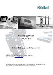
Dimensions & clearancesFront ViewSide ViewRear ViewABB1F95120205D13586 H85643W1 K G W281197 162 16274154B2Dimensions TH-L50 TH-L65 TH-L85 TH-L100 TH-L120 TH-L145Bottom View / ClearancesB mm 490 490 490 590 590 590B1 mm 140 140 140 140 140 190B2 mm 245 245 245 295 295 295D mm 500 500 500 600 600 600100mm200mmH mm 810 810 810 950 950 950W1 (Flow) mm R1 1 /4” R1 1 /4” R1 1 /4” R1 1 /2” R1 1 /2” R1 1 /2”W2 (Rtn) mm R1 1 /4” R1 1 /4” R1 1 /4” R1 1 /2” R1 1 /2” R1 1 /2”G (Gas) mm R 3 /4” R 3 /4” R 3 /4” R1” R1 R1”1000mmF (Flue) mm 100 100 100 100 100 130A (Air) mm 100 100 100 100 100 130K mm 22 22 22 22 22 227
Controls and OptionsThe ability to control the charging of an indirect hot water cylinder, with time scheduling is a standardfeature of the <strong>Ultramax</strong> <strong>Thision</strong> L boilers. Heating circuits, either, constant temperature, weather variablevia mixing valves or weather variable via direct-on-boiler compensation may be controlled by theinclusion of optional extra control components as listed below. Multiple boiler cascade control systemsare easily created by the inclusion of bus communication modules in the boilers.Outside air temperature sensorQAC34. Allows weather compensated heating flow circuitflow temperatures to be provided. QAC34 Wireless.As above but with the inclusion of an AVS13 wirelesstransmitter. This kit must be used in combination with thewireless receiver unit (AVS71) to enable wirelesscommunication between the outside air temperature sensorand the boiler.Heating zone sensorQAD36. Heating zone clamp-on temperature sensor, for usewhen any heating zone included in the control scheme isweather compensated and the variable flow temperature iscontrolled via a mixing valve.Header/hot water sensorQAZ36. Kit includes a QAZ36 sensor with 6m lead and a ½”BSP threaded sensor pocket for use either as a (low loss)header sensor or as a hot water cylinder temperature sensor.sensor and the boiler.Room unitQAA75. Room unit for the time and temperature control ofany connected heating zone. Every heating zone may have anindividual room unit connected, providing for differing timeand temperature scheduling in different areas of a building ifdesired. QAA78 Wireless. Using wireless communication,the QAA78 device provides the same control features as theconventionally wired QAA75 unit described above. TheQAA78 Wireless unit must be used in combination with thewireless receiver unit (AVS71) to enable wirelesscommunication between the room control unit and the boiler.Wireless ReceiverAVS71. When connected to a <strong>Thision</strong> L boiler it can transmitand receive data between wireless room units (QAA78) and /or receive information from a wireless outside air temperaturesensor arrangement (QAC34 +AVS13).Extension modulesAGU2.550. Including a communication cable for connectionto the boiler’s control system, up to 3 AGU2.550 extensionmodules may be installed into a <strong>Thision</strong> L boiler. Modules 1& 2 for the control of heating zones (one module per heatingzone, with the capability to drive a heating zone circulationpump and a 3 way mixing valve (if fitted)). Module 3 is usedif it is required to control an external gas valve.Up to 2 x AGU2.550 extension modules for the control ofheating zones may be installed per boiler in a cascadeinstallation, for the control of up to a maximum of 8 heatingzones per system. Up to a maximum of 8 heating zones mayalso be controlled in conjunction with a single boiler ifrequired, with zones 1 & 2 being controlled by 2 x AGU2.550extension modules installed within the boiler, and zones 3 to8 being controlled by Logon B controllers (see below).AGU2.551. Including a communication cable for connectionto the boiler’s control system, the AGU2.551 is used when aspeed controlled 0-10V (modulating) boiler pump is utilised.It will also provide a 0-10V output feedback signal to a BMSsystem for boiler firing rate monitoring purposes.Logon B with wall hung boxA wall mounted console including a controller which allowsthe connection and control of up to 2 additional heatingzones and an additional hot water cylinder.Cascade Controls(Up to 16 boilers may be included within a cascade controlarrangement) Cascade kit - Master. Kit includes an OCI345communication module and a (QAZ36) header sensor.The communication module is mounted within the first(master) boiler of a multiple boiler cascade installation.Cascade kit - Slave. Kit includes an OCI345 communicationmodule. A Cascade kit – Slave is required to be installedwithin every additional boiler (over and above the Master) ina cascade installation.8
Accessories – Wall MountedLow Loss HeadersAs an aid to installation, a range of wall mounted prefabricated vertical low velocity headers are availablefor either single boiler applications or installer fabricated multi – boiler installations. Prefabricatedinsulating jackets for the headers are also available.Vertical Low Velocity HeadersData Type A Type B Type C Type D Type ETappings a 1/2" BSP-F 1/2" BSP-F 1/2" BSP-F 1/2" BSP-F 1/2" BSP-FTappings b 1 1 /4" BSP-F 2" BSP-F 2" BSP-F 2 1 /2" BSP-F 3" BSP-FW mm 50 60 100 120 150Depth mm 50 60 100 120 150Distances C from wallto L Tappingsmm 205 205 205 205 205G mm 285 280 470 470 470H mm 345 350 540 570 570I mm 44 44 44 66 66J mm 95 120 120 120 120K mm 44 44 44 44 44Duty @ 20k ∆t kW Up to 90 91 to 155 156 to 300 301 to 500 501 to 600Type LLH65 LLH100a1 (boilers) DN65 PN16 DN100 PN16a2 (system) DN65 PN16 DN100 PN16b(air venttapping)c(sensortapping)d(tapping fordrain)¾” BSPFemale½” BSPFemale¾” BSPFemale¾”BSPFemale½” BSPFemale¾” BSPFemaleD1 350mm 475mmH1 935mm 1150mmH2 445mm 620mmH3 305mm 460mmH4 290mm 330mmNote:Vertical lowvelocity headersare reversible inorder that theymay be installedat either the lefthand side, orright hand sideof a boiler/sinstallation.GAir VentSensoraabb 30160 100IHFlow toSystemDistance from wallto centre line oftappings = 215mmStandard type low loss headerfor boiler cascade systemsH3a1cba2H2H1DrainbaWbaJKReturn fromSystema1da2H4260Fill PointD19
Accessories - Cascade SystemsThe cascade system optional accessories shown in the following drawings consist of themounting frame components complete with interconnecting gas and water pipes(boiler cascade set), and also the cascade installation flue headers (flue cascade set),and which are two separate sets of components designed to complement one another.The boiler cascade set may be utilised with suitable alternative flue arrangements as/if necessary. The cascade flue sets are purposedesigned and matched kits of components fabricated from corrosion resistant PPS material. The individual branches are connectedinto the main header via a swept arrangement to ensure minimum resistance to flow and they are engineered to provide the correctfall back towards the (included) condense waste outlet syphon. A very important feature of the cascade flue set is the inclusion of anon return valve in each individual boiler flue leg which prevents the possibility of flue gas recirculation from operating appliancesinto any non-firing unit.Options: Cascade systems are available for "Wall-Mounting In-Line" for 2 to 6 boilers, "Free-Standing In-Line" for 2 to 6 boilersand Free-Standing Back-to-Back from 3 to 8 boilers. Also available, to compliment the cascade pipe work sets are preformed easyto-fitinsulation sets, which not only reduce heat loss and plant room temperatures but also create pleasing aesthetics for thecompleted cascade installation.Cascade Wall-Mount In-Line (in a row on the wall)CWL2 CWL3 CWL4 CWL5 CWL6Cascade Free-Standing In-Line (in a row free standing)CFL2 CFL3 CFL4 CFL5 CFL6Cascade Free-Standing Back-to-Back (back to back free standing)CFBB3 CFBB4 CFBB5 CFBB6 CFBB7 CFBB8The Cascade sets are available with an option of either a standard low loss header or a header that incorporates also dirt and airseparation features. Both types of header are available with system connection sizes of either DN65 for outputs up to 462kW orDN100 for outputs from 463 to 1140kW @ Δt 20KFor complete hydraulic separation, cascade sets incorporating a plate type heat exchanger (as an alternative to a low loss header)are available for duties up to 462kW.Guidance for selection of cascade (water) header connection sizeDN65 Connections (for outputs up to 462kW)DN100 Connections (for outputs 463kW to 1140kW)BoilerModelsNumber of Boilers2 3 4 5 62 xAnyTh-LModel3 xAnyTh-LModel4 x TH-L50 5 x TH-L50 6 x TH-L504 x TH-L65 5 x TH-L65 6 x TH-L654 x TH-L85 5 x TH-L85 6 x TH-L854 x TH-L100 5 x TH-L1004 x TH-L120BoilerModelsNumber of Boilers4 5 6 7 84 x TH-L145 5 x TH-L120 6 x TH-L100 7 x5 x TH-L145 6 x TH-L120 Any6 x TH-L145 TH-L Model8 xAnyTH-L Model10
Cascade SystemsDimensionsIn-Line systems with Low Loss Header withDN65 Connections681 650345677*560, **660BøD18101691DN 651776339644538R 2"H3º241L445The low loss headers shown in the above diagram depict the optional unit which includes dirt and air separation features.As an alternative, a standard type unit is available, see page 9 for details.See page 17 for guidance on selection/suitability of flue cascade common header diameter.Number of Boilers 2 3 4 5 6L mm 1672 2322 2972 3622 4272øD = 150mm B = 400 - 450 H mm 553 646 738 831 924øD = 200mm B = 350 - 450 H mm 616 709 801 894 987* = <strong>Thision</strong> L 50 - 85, ** = <strong>Thision</strong> L 100 - 145Note: maximum output with DN65 system water connections is limited at 462kW @ Δt 20K11
Cascade SystemsDimensionsIn-Line systems with Low Loss Headerwith DN100 Connections1115650345660577BøD18104085381831868H3ºDN 1001916L445241DN 65The low loss headers shown in the above diagram depict the optional unit which includes dirt and air separation features.As an alternative, a standard type unit is available, see page 9 for details.See page 17 for guidance on selection/suitability of flue cascade common header diameter.Number of Boilers 4 5 6L mm 3407 4057 4707øD = 150mm B = 400 - 450 H mm 738 831 924øD = 200mm B = 350 - 450 H mm 801 894 98712
Cascade Systems DimensionsIn-Line systems with plate type heat exchangerwith DN80 connectionsHeat Exchanger Type / DutyBoiler Models TH - L 50 - 85 TH - L 100 - 145∆t 10KkW >250 251 - 462Type CB200-30M CB200-64M∆t 15K - 20KkW >250 251 - 462Type CB200-30M CB200-50M945 650 345681CB200-30M = 92CB200-50M = 146CB200-64M = 184720*560 , **660BøDDN 80339538644624R 2"1052181016911776H3º241L445See page 17 for guidance on selection/suitability of flue cascade common header diameter.Number of Boilers 2 3 4 5 6L mm 1940 2590 3240 3890 4540øD = 150mm B = 400 - 450 H mm 553 646 738 831 924øD = 200mm B = 350 - 450 H mm 616 709 801 894 987* = <strong>Thision</strong> L 65-85, ** = <strong>Thision</strong> L 100 - 145Note: the In-Line cascade system incorporating a plate heat exchanger as the interface between the boiler set and the system islimited to 462kW (as per the heat exchanger type and duty table at the top of the page). Ensure that the numbers of boilersselected, multiplied by their individual output, does not exceed a maximum of 462kW. Plate heat exchangers by others must beutilised for installations of outputs greater than 462kW.13
Cascade SystemsDimensionsBack-to-Back systems with Low Loss Headerwith DN65 Connections681 650345677*530, **630 530øD18101691DN 653396445381776R 2"H3º241L445The low loss headers shown in the above diagram depict the optional unit which includes dirt and air separation features.As an alternative, a standard type unit is available, see page 9 for details.See page 17 for guidance on selection/suitability of flue cascade common header diameter.Number of Boilers 3 - 4 5 - 6L mm 1672 2322øD = 150mm H mm 553 646øD = 200mm H mm 616 709* = <strong>Thision</strong> L 50 - 85, ** = <strong>Thision</strong> L 100 - 145Note: maximum output with DN65 system water connections is limited at 462kW @ Δt 20K14
Cascade SystemsDimensionsBack-to-Back systems with Low Loss Headerwith DN100 Connections1115650345577*530 , **630 *530 , **630øD4085388681810 3º1831H1916LDN 100445241DN 65The low loss headers shown in the above diagram depict the optional unit which includes dirt and air separation features.As an alternative, a standard type unit is available, see page 9 for details.See page 17 for guidance on selection/suitability of flue cascade common header diameterNumber of Boilers 3 - 4 5 - 6 7 - 8L mm 2107 2757 3407øD = 150mm H mm 53 646 738øD = 200mm H mm 616 709 801* = <strong>Thision</strong> L 65-85, ** = <strong>Thision</strong> L 100 - 14515
Cascade SystemsDimensionsBack-to-Back systems with plate typeheat exchanger with DN80 connectionsHeat Exchanger Type / DutyBoiler Models TH - L 50 - 85 TH - L 100 - 145∆t 10KkW >250 251 - 462Type CB200-30M CB200-64M∆t 15K - 20KkW >250 251 - 462Type CB200-30M CB200-50M945650345681CB200-30M = 92CB200-50M = 146CB200-64M = 184690*530 , **630 *530 , **630øDDN 80339538644R 2"6241810105216911776H3º241L445See page 17 for guidance on selection/suitability of flue cascade common header diameter.Number of Boilers 3 - 4 5 - 6 7 - 8L mm 1940 2590 3240øD = 150mm H mm 553 646 738øD = 200mm H mm 616 709 801* = <strong>Thision</strong> L 65-85, ** = <strong>Thision</strong> L 100 - 145Note: the Back-to-Back cascade system incorporating a plate heat exchanger as the interface between the boiler set and the systemis limited to 462kW. Ensure that the numbers of boilers selected, multiplied by their individual output, does not exceed a maximumof 462kW. Plate heat exchangers by others must be utilised for installations of outputs greater than 462kW.16
Flue SystemsThe optional flue cascade sets are available in either 150mm or 200mm diameter forboth the "In-Line" and "Back-to-Back" boiler cascade sets.The diameter of the horizontal collector part of the flue cascade sets (150 or 200mm diameter) and the vertical chimney (fromthe flue cascade set to the terminal position) depends upon the total heat output of the installation (based upon full loadboiler heat output @ 80/60°C – see technical data on page 6) and the vertical height of the chimney. Prefabricated cascadesets are available for cascade boiler installations of up to 834kW output (see table below).The table shows the maximum system output related to the vertical chimney length (based upon a maximum horizontal lengthof 3m after the flue cascade set and the diameter (collector diameter/chimney diameter).Example: The maximum heat output of a cascade installation of <strong>Ultramax</strong> <strong>Thision</strong> – L Boilers when using a 200mm diameterflue cascade set, connected to a 250mm diameter vertical chimney of 15m height is 658kW.Maximum output (kW) o f boiler cascade @ 80/60°Cby flue cascade diameter and vertical chimney lengthDiameter(collector Ø/chimney Ø)Vertical chimney Length5m 15m 30m150mm / 150mm 319 305 281150mm / 200mm 439 402 361200mm / 200mm 517 488 470200mm / 250mm 680 658 630200mm / 300mm 834 815 777A = 380B = 450C = 450A = 810B = 810C = 950A = 230B = 230C = 230Max effectivelength “EL”(wall thickness)A = 740B = 690C = 690ELA = 175B = 180C = 180A = 125B = 150C = 150Parallel toconcentricadaptorGuidance on flue systems for single boilersModel<strong>Ultramax</strong><strong>Thision</strong> LFlue gastemperature@ flow /return80/60°CFlue gasvolumeMaximum fluesystemresistance°C m³h Pa50 76 88 15065 76 119 15085 76 159 150100 76 178 150120 76 213 200145 76 253 200Model<strong>Ultramax</strong>*Maximum length of straight flue pipe in metres<strong>Thision</strong> L Ø 80mm Ø 100mm Ø 110mm Ø 125mm Ø 130mm50 17 7065 10 6585 30 51100 20 34 42 44120 32 54 68 70145 18 31 38 40*Includes an allowance for up to 1.5m of horizontal flue pipe and 2 x 87° bendsin the connector piece from the boiler to the main straight flue pipe installation.The above listed maximum lengths of flue pipe are relative to an open flue typeinstallation; if the installation is room sealed then the lengths apply to air inlet andflue pipe lengths combined.For every bend that is introduced into the system, the maximum length must bereduced by 1m.The maximum horizontal length of flue pipe that may be installed is 20m; burnerignition difficulties may result from longer horizontal lengths.A = Boiler models <strong>Ultramax</strong> <strong>Thision</strong> L 50 & 65B = Boiler model <strong>Ultramax</strong> <strong>Thision</strong> L 85C = Boiler models <strong>Ultramax</strong> <strong>Thision</strong> L 100, 120 & 145As standard <strong>Ultramax</strong> <strong>Thision</strong> L boilers have independant connectionsfor combustion air supply and flue gas (parallel tubes). To utilise aconcentric flue system, either 80/125 for the models 50 & 65 or110/150 for all other models, an adaptor is required as shown in thediagram on the left. A horizontal flue arrangement is shown but theadaptor may also be used for a vertical concentric flue installation.Model<strong>Ultramax</strong><strong>Thision</strong> LMaximum length of straightconcentric flue pipe in metresØ 80/125mmØ 110/150mm50 9 1265 5 785 - 6100 - 5120 - 6145 - 417
System waterAll systems must be thoroughly cleansed prior to connection of the boiler and the systemwater must be dosed with a good quality water treatment to prevent corrosion within thesystem and formation of scale within the boiler waterways. For detailed guidance on waterquality, refer to either the installer guide or the planning documentation which is availableby visiting MHS Boilers web site @ www.mhsboilers.comThe chloride content of the fill water must not exceed 50mg/l and the PH should be in the range 8.0 to 9.5. Particular care must betaken when installing the boiler onto an old system, with consideration given to the installation of the optional extra separation “plateheat exchanger kit” or a dirt arrester/filter.For specialist advice and water treatment products, contact: Cookson Electronics (Fernox) Forsyth Road, Sheerwater, Woking SurreyGU21 5RZ Tel: 01483 793200 or Betz Dearborn Ltd, Foundry Lane Widnes, Cheshire WA8 8UD. Tel: 0151 495 1861Installation requirements<strong>Ultramax</strong> <strong>Thision</strong> L series boilers should be installed in accordance with the relevant requirements of the Building Regulations,Health and Safety Executive Regulation PM5, IEE Regulations, Gas Safety (Installation and Use) Regulations, National and WaterBylaws and any Insurance Company requirements.Codes of practiceThe following list of codes of practice give guidance on the requirements for system design and installation.BS 6880-2:1988Code of Practice for low temperature hot water heatingsystems for output greater than 45kW.BS 6644:2005+A1:2008Installation of gas-fired hot water boilers of rated inputsbetween 70kW (net) and 1.8MW (net).BS EN 12828:2003Heating systems in buildings - design for water basedheating systems.CISBE GuideReference sections B7, B11 and B13.IGE/UP/2 Gas installation pipework and compressors onindustrial and commercial premises.IGE/UP/10 Installation of gas appliances in industrial andcommercial premises, Part 1: Flued appliances.Filling the systemThe initial filling of a sealed heating system and subsequent refilling must be by a method that has been approved by the WaterRegulations Advisory Scheme (WRAS) for the type of heating system, i.e. Non Domestic (other than in-house) Fluid Category 4 (C4).For Category 4 systemsThe approved method of filling must comprise of the followingcomponents in the arrangement shown;• Control Valve, on the Mains Cold Water pipework.• Strainer.• Verifiable Backflow Device with Reduced Pressure Zone(RPZ Valve) Incorporating a ‘Type BA’ air gap.• Tundish• Control Valve, on the Heating System pipework.• Alternatively, the use of a Pisces Minifill PressurisationManager from MHS Boilers meets all of the requirements –see appropriate literature or visit www.mhsboilers.comRPZMCWS CV StrainerCVTundishHeatingsystem18
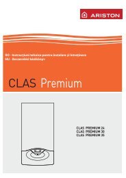
Hydraulic system design<strong>Ultramax</strong> Thison L Series Boilers are designed to operate with a nominal Δt 20ºC.The water system shall be sealed and pressurized with a minimum static head of 10m(1bar) for operation at 80ºC or 15m (1.5bar) for operation at 90ºC. The system shall bewater treated in accordance with BS 7593:2006, code of practice for treatment of hotwater central heating systems.Single boiler schematicQAC34QAA75QAA75Heating Zones1 2Typical single boiler installation schematic with 2 nrheating zones plus a domestic hot water cylinder.Both heating zones may be with or without VT mixingvalve included.CondenseWastePUSV<strong>Ultramax</strong><strong>Thision</strong> LBoilerIV**FPDOCIVLSVAAVLow Velocity Mixing HeaderMax. Velocity 0.5m/sDOCStrainerQAZ36MVNRVQAZ36IndirectHot WaterCalorifierCTLegend for system schematics* Extension module AGU2.550(optional extra component)installed within boilerQAC34 Outside air temperature sensorQAA75 Room control unitQAZ36 Water temperature sensor for lowloss header, VT heating zone andhot water cylinderCT Cylinder thermostat (may be usedas an alternative to a QAZ36 on ahot water cylinder)CWMExpansionVesselQAC34LSVDOCCascade schematicQAA75QAA75CWMPUFPLSVDOCAAVCold water mainSealed system pressurisation unitFilling point (Refer to waterregulations for acceptablemethod)Lockshield valveDrain tapAir ventHeating Zones1 2MVNRVVT mixing valveNon return valve<strong>Ultramax</strong><strong>Thision</strong> LBoiler<strong>Ultramax</strong><strong>Thision</strong> LBoilerQAZ36IVSVIsolation valveSafety relief valveS**MCondenseWasteSVCWMAAVSVDOCIV IV IV IVQAZ36NRVNRVPUExpansionVesselFPLSVLSVLow Velocity Mixing HeaderMax. Velocity 0.5m/s 0.5m/sDOCStrainerMVQAZ36IndirectHot WaterCalorifierCTTypical cascade boilerinstallation schematic with 2nr heating zones plus adomestic hot water cylinder.Both heating zones may bewith or without VT mixingvalve included.DOC19
RC/0611/63163 Juniper West, Fenton Way, Southfields Business Park,Basildon, Essex SS15 6SJTel: 01268 546700 Fax: 01268 888250www.mhsboilers.com20This publication is issued subject to alteration or withdrawal without notice.The illustrations and specifications are not binding in detail. All offers and salesare subject to the Company's current terms and conditions of sale.