
You also want an ePaper? Increase the reach of your titles
YUMPU automatically turns print PDFs into web optimized ePapers that Google loves.
<strong>EN</strong> <strong>71</strong>-1:<strong>2005+</strong><strong>A8</strong>:2009 (E)<br />
Key<br />
52<br />
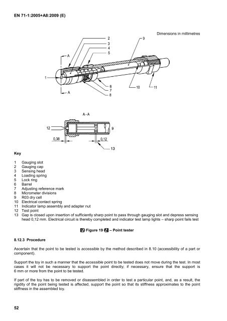
Dimensions in millimetres<br />
1 Gauging slot<br />
2 Gauging cap<br />
3 Sensing head<br />
4 Loading spring<br />
5 Lock ring<br />
6 Barrel<br />
7 Adjusting reference mark<br />
8 Micrometer divisions<br />
9 R03 dry cell<br />
10 Electrical contact spring<br />
11 Indicator lamp assembly and adapter nut<br />
12 Test point<br />
13 Gap is closed upon insertion of sufficiently sharp point to pass through gauging slot and depress sensing<br />
head 0,12 mm. Electrical circuit is thereby completed and indicator test lamp lights – sharp point fails test<br />
8.12.3 Procedure<br />
-Figure 19. – Point tester<br />
Ascertain that the point to be tested is accessible by the method described in 8.10 (accessibility of a part or<br />
component).<br />
Support the toy in such a manner that the accessible point to be tested does not move during the test. In most<br />
cases it will not be necessary to support the point directly; if necessary, ensure that the support is<br />
6 mm or more from the point to be tested.<br />
If part of the toy has to be removed or disassembled in order to test a particular point, and, as a result, the<br />
rigidity of the point being tested is affected, support the point so that its stiffness approximates to the point<br />
stiffness in the assembled toy.