You also want an ePaper? Increase the reach of your titles
YUMPU automatically turns print PDFs into web optimized ePapers that Google loves.
<strong>EN</strong> <strong>71</strong>-1:<strong>2005+</strong><strong>A8</strong>:2009 (E)<br />
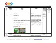
Adjust the point tester (8.12.2) by loosening the locking ring and rotating it so that it moves a distance toward<br />
the indicator lamp assembly sufficient to expose the calibration reference mark on the barrel. Rotate the<br />
gauging cap clockwise until the indicator lamp lights. Rotate the cap counter-clockwise until the sensing head<br />
moves a distance of (0,12 ± 0,02) mm from making contact with the dry cell, as shown -in Figure 19..<br />
NOTE Where the gauging cap includes micrometer markings, the distance may be readily achieved by rotating the<br />
cap counter-clockwise until the appropriate micrometer marking corresponds to the calibration reference mark. The<br />
gauging cap may now be locked in this position by rotating the locking ring until it fits firmly against the cap.<br />
Insert the point into the cap slot in the direction which confers the greatest rigidity on the point, and apply a<br />
force of 4,5 N to depress the spring as far as possible without shaving the point on the edges of the slot or<br />
extruding the point through the slot.<br />
Determine whether or not the indicator lamp lights up.<br />
If the point penetrates a distance of 0,50 mm or more into the gauging slot, causing the indicator lamp to light,<br />
and the point maintains its original shape while under a force of 4,5 N, the point tested is considered to be a<br />
sharp point.<br />
8.13 Flexibility of +metallic, wires (see 4.8 and A.41)<br />
8.13.1 +General<br />
If the metallic wire has a covering, apply the test to the metallic wire in the condition in which it appears in the<br />
toy (i.e. do not remove the metallic wire from the toy).<br />
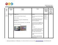
Grip the metallic wire firmly between two metal cylinders, radiused pliers, or equivalent metal pieces with a<br />
diameter of (10 ± 1) mm. At a point 50 mm from the point of gripping or, if less than 50 mm protrudes, at the<br />
end of the metallic wire, apply a force of (70 ± 2) N perpendicular to the metallic wire. If the metallic wire<br />
bends more than 60°, continue the test as follows.<br />
Bend the metallic wire from the upright position to one side through 60°, and then bend in the opposite<br />
direction through 120°, and finally return to the upright position. This is one cycle.<br />
8.13.2 Metallic wires and other metallic components intended to be bent<br />
Perform the cycle described in 8.13.1 (general) 30 times at a rate of one cycle per 2 s with a 60 s rest period<br />
after each 10 cycles. To ensure that the metallic wire or other metallic component bends at the point emerging<br />
from the cylinders, it shall be kept taut during the test.<br />
Examine the metallic wire or metallic component for breakage or hazardous sharp points (8.12, sharpness of<br />
points), removing any covering material, if applicable, to aid the examination.<br />
8.13.3 Metallic wires likely to be bent<br />
Perform the cycle described in 8.13.1 (general) one time.<br />
Examine the metallic wire for breakage or hazardous sharp points (8.12, sharpness of points), removing any<br />
covering material, if applicable, to aid the examination.,<br />
8.14 Expanding materials (see 4.6)<br />
Condition the toy or component at (20 ± 5) °C and at a relative humidity of 40 % to 65 % for at least 7 h before<br />
the test. Measure the maximum dimensions of the toy or any component of the toy in the x, y and z<br />
dimensions using callipers. Submerge the toy or component completely in a container of demineralised water<br />
at (20 ± 5) °C for (72 ± 0,5) h. Ensure that sufficient water is used so that the toy or component still remains<br />
under water at the end of the test.<br />
53