Presentation 2nd IAG Task1 Codes of practice - ESR Technology
Presentation 2nd IAG Task1 Codes of practice - ESR Technology
Presentation 2nd IAG Task1 Codes of practice - ESR Technology

Create successful ePaper yourself
Turn your PDF publications into a flip-book with our unique Google optimized e-Paper software.
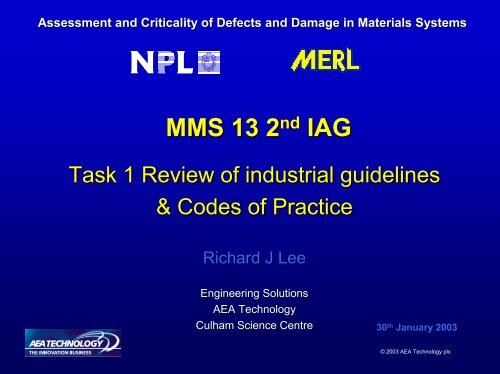
Assessment and Criticality <strong>of</strong> Defects and Damage in Materials SystemsMMS 13 2 nd <strong>IAG</strong>Task 1 Review <strong>of</strong> industrial guidelines& <strong>Codes</strong> <strong>of</strong> PracticeRichard J LeeEngineering SolutionsAEA <strong>Technology</strong>Culham Science Centre30 th January 2003© 2003 AEA <strong>Technology</strong> plc
Assessment and Criticality <strong>of</strong> Defects and Damage in Materials Systems• Purpose– Review & assess current industrial guidelines & codes <strong>of</strong> <strong>practice</strong>from a range <strong>of</strong> industrial sectors• Procedure– Review existing guidelines for defect assessment (Dow, CEN, BSI,ISO, ASME, NORSOK, ESA, NASA, Boeing, MIL HDBK-17, etc.)– Examine defect types applicable to various materials systems– Review approaches for different industry sectors– Compare defect assessment codes for metallics– Task 1 report issued to <strong>IAG</strong> for comment and subsequently revised© 2003 AEA <strong>Technology</strong> plc
MMS 13 Assessment and Criticality <strong>of</strong> Defects & Damage in Materials SystemsTask 7Case studiesIndustrysupport(range <strong>of</strong>sectors)Task 6Draft procedural guideTask 8DisseminationTask 2 – Experimental testing (material data from MERL)Task 3 – NDE assessment (acoustic emission information from Brunel)Task 4 – Defect characterisationTask 5 – Assessment <strong>of</strong> defect criticalityTask 1- Review <strong>of</strong> industrial guidelines &<strong>Codes</strong> <strong>of</strong> PracticeOther/ past programme inputsCPD, DCC, VAMAS, MMS4, MMS5, MMS15, IACFA, AMCAPSIIAEA main tasks© 2003 AEA <strong>Technology</strong> plc
Assessment and Criticality <strong>of</strong> Defects & Damage in Materials SystemsTask 1 Review– Identify• Damage mechanisms and defect types• Current approaches for assessment <strong>of</strong> defects in compositestructures• Best <strong>practice</strong>– Determine capability <strong>of</strong> available inspection techniques– Establish what is currently available and identify where furtherdevelopment is required© 2003 AEA <strong>Technology</strong> plc
Assessment and Criticality <strong>of</strong> Defects & Damage in Materials SystemsTask 1 Review• Defect growth mechanisms– Delamination– Matrix microcracking– Fatigue– Fibre debonding– Matrix thermal and chemical degradation– Environmentally assisted cracking• Analysis techniques– estimation <strong>of</strong> critical defect dimensions– estimation <strong>of</strong> defect growth rates• Inspection techniques for composite structures© 2003 AEA <strong>Technology</strong> plc
Assessment and Criticality <strong>of</strong> Defects & Damage in Materials SystemsMaterials SystemsUnidirectional laminatesMultidirectional laminatesSandwich structures© 2003 AEA <strong>Technology</strong> plc
Assessment and Criticality <strong>of</strong> Defects & Damage in Materials SystemsProperty dataply propertieslaminate stress strain curveInitiation and propagation <strong>of</strong> damagetransverse crackingdelaminationSignificant damage processes related to failure eventsinitial crackingcrack saturationdelaminationchange in elastic propertiesstress redistribution resulting in delayed fibre failure© 2003 AEA <strong>Technology</strong> plc
MATERIALSYSTEMTYPICAL APPLICATIONSTYPES OFDAMAGERESIDUALLOADING MODESPre-preg carbonfibre/epoxy andsandwichstructuresAerospaceAutomotiveBuilding and ConstructionSports equipmentDelaminationFibre breakageMatrix cracking- compression- tension- flexure/shear- fatigueChopped-strandmatglass-fibre/polyesterMarineWater and chemical tanks, process piping,RailConstructionHousingsTransportationFibre breakageLarge matrixcracksFibre pull-out- compression- tension- flexure/shearGlass-fibre/polyesterpultrusionChemical plantAutomotive and rail components. Ladders, cable trays. Switch gearcomponents.Civil Engineering - composite bridgesSmall amount <strong>of</strong>delaminationMatrix cracking- compression- tension- flexure/shearTherm<strong>of</strong>ormedglass-fibre mat/polypropyleneAutomotive -shields, under-body structures, trays, dashboardsBeamsMarine hullsFibre pull-outMatrix cracking- tension- flexure/shearPre-pregglass-fibrefabric epoxyElectrical applications, circuit boards.Automotive leaf springsStructural applications – wind turbinesMatrix crackingFibre breakageFibre pull-out- tensionInjection mouldedglass-fibre/polypropyleneAutomotiveConsumerBuilding/hardwareMarineUnderwater systemsFibre pull-outMatrix cracking- tension- compression-flexureMaterial Systems Applications, Main Defect Types and Loading Modes
Assessment and Criticality <strong>of</strong> Defects & Damage in Materials SystemsDefect TypesInclusionsDebondingDelaminationFibre breakageManufacturing defectsIn-service defectsImproper splicing/ joiningFibre misalignment and wrinklingIncorrect stacking sequencePorosityResin starved areasDamage from tooling removalMachining imperfectionsMatrix CrackingHeat damage© 2003 AEA <strong>Technology</strong> plc
Porosity
Interlaminar andTransverse cracking© 2003 AEA <strong>Technology</strong> plc
Delamination© 2003 AEA <strong>Technology</strong> plc
Matrix cracking/delamination after impact
GRP pipe transportation damage
Assessment and Criticality <strong>of</strong> Defects and Damage in Materials Systems• Specific IssuesHow do we characterise damage ?What techniques are available ?What assessment criteria are available ?© 2003 AEA <strong>Technology</strong> plc
MMS 13 Assessment and Criticality <strong>of</strong> Defects & Damage in Materials SystemsMETHODS OF CHARACTERISING DEFECTSDESTRUCTIVE TECHNIQUESOptical and scanning electron microscope(SEM) fractography,De-plyingEdge replication (thin laminates)© 2003 AEA <strong>Technology</strong> plc
Assessment and Criticality <strong>of</strong> Defects & Damage in Materials SystemsNON DESTRUCTIVE TECHNIQUESVisual inspectionUltrasonic c-scans (reflection & transmission)X-radiographyLaser shearographyThermographyTap/ vibration testingAcoustic emissionOther© 2003 AEA <strong>Technology</strong> plc
Methods for inspecting large areasMinimum <strong>of</strong> expert interpretationLocation with latest informationPerformance data on real manufacturing and service defectsQuality control limits linked to pro<strong>of</strong> test requirementsSpeed <strong>of</strong> data interpretationDefect assessment manufacturingAssessment <strong>of</strong> repair qualityInspection <strong>of</strong> metal components through composite repairsQuantitative performance informationLack <strong>of</strong> suitable standardsImproved defect assessmentUnderstanding <strong>of</strong> damage mechanisms relevant in-serviceUse <strong>of</strong> data in life assessment and maintenance planningImproved classification <strong>of</strong> defectsSimple, rapid, reliable methods for in-service assessment© 2003 AEA <strong>Technology</strong> plc
APPLICATIONS IN INDUSTRY SECTORSPROCESS INDUSTRIESOIL & GAS REFININGOFFSHOREAEROSPACEAUTOMOTIVEMARINECONSTRUCTION
REVIEW OF EXISTING DESIGN STANDARDS & GUIDELINESincluding manufacturing defect assessmentBS 4994 :1987ASME RTP-1:1995ASME X: 2001ISO 14692: 2002DNV F-100: F2001EN 13706: 2001NORSOK M-622: M1999Dow Chemicals SpecificationsESA Composite Design Handbook GuidelinesCommercial aircraft industry guidelines (NASA/ Boeing & Airbus)MIL-HDBKHDBK-17: 2002© 2003 AEA <strong>Technology</strong> plc
BS 4994: 1987 Table 16 - Permissible limits for laminate defectsDefect Inner (process) surface (thermoset linings only) Outer (non-process) surfaceBlisters None Maximum 6 mm diameter, 1.5 mm highChips None Maximum 6 mm, provided it does notCracks None NoneCrazing None Slightpenetrate the reinforcing laminateDry spotsEntrapped airNoneNone at surface. If in laminate,Maximum 10 per m 2 with total notgreater than 100 mm 2 in area3 mm diameter maximum; inot greater than 1.5 mm diameter andno more than 3 % <strong>of</strong> areanot more than 2/100 mm 2Exposed glass None NoneExposed cut edges None NoneForeign matter None None if it affects the properties<strong>of</strong> the laminatePits Maximum 3 mm diameter, 0.5 mm deep, Maximum 3 mm diameter, 1.5 mm deepnumber shall not exceed 1/10 4 mm 2Scores Maximum 0.2 mm deep Maximum 0.5 mm deepSurface porosity None NoneWrinkles Maximum deviation 20 % <strong>of</strong> wall thickness Maximum deviation 20 % <strong>of</strong> wall thicknessbut not exceeding 3 mmbut not exceeding 4.5 mmSharp discontinuity Maximum 0.5 mm Maximum 1 mm© 2003 AEA <strong>Technology</strong> plc
MMS 13 Assessment and Criticality <strong>of</strong> Defects & Damage in Materials SystemsASME/ ANSI RTP-1: 1995American National Standard covering reinforced thermoset plasticcorrosion resistant equipmentMaterials covered by the standard include the following :Glass fibre reinforcements in the form <strong>of</strong> surface veils, random mat (choppedstrand mat or CSM), woven fabrics, unidirectional rovings (typically to be usedin filament winding)Matrix systems including polyester and vinyl esterThermoplastic linersStandard allows for fabrication by hand lay up and/or filament winding.© 2003 AEA <strong>Technology</strong> plc
© 2003 AEA <strong>Technology</strong> plc
MMS 13 Assessment and Criticality <strong>of</strong> Defects & Damage in Materials SystemsASME X: 2001ASME Boiler and Pressure Vessel Code and applies specifically to fibrereinforced plastic pressure vesselsGlass-fibre reinforcements in the form <strong>of</strong> surface veils, random mat(chopped strand mat or CSM), woven fabrics, unidirectional rovings(typically to be used in filament winding). ASME X also allows for otherfibre reinforcement types including carbon/graphite and aramid fibres.Matrix systems including polyester, vinyl ester, epoxy, phenolic andfurane.Thermoplastic liners, e.g. PVC, PFA.© 2003 AEA <strong>Technology</strong> plc
Allowable defects as defined by ASME V and ASTM D 2563as defined by ASME V and ASTM D 2563
MMS 13 Assessment and Criticality <strong>of</strong> Defects & Damage in Materials SystemsISO 14692: 2002Qualification, system design and operation <strong>of</strong> GRP pipe systemsPipe systems include both pipelines and piping systems.Intended primarily for the oil and gas industry and covers both on-shoreand <strong>of</strong>f-shore applications© 2003 AEA <strong>Technology</strong> plc
MMS 13 Assessment and Criticality <strong>of</strong> Defects & Damage in Materials SystemsISO 14692: 2002GRP material/ adhesive bondsDefect type Description Criteria Corrective actionManufactureBlisteringBurn/DiscolorationChalking andloose fibresChemicalattackBlisters forming under outer plies <strong>of</strong>laminate or inner resin rich layerThermal decomposition evidenced bydistortion or discoloration <strong>of</strong> the laminatesurfaceMinor breakdown <strong>of</strong> outer surface dueto UV radiation or acid rain, caused bystorage over prolonged periodCorrective actionDeliveryCorrective actionInstallationCorrective actionOperationNone permitted Reject Reject Reject / Major repair Acceptable if noleakageDistortion and/or burn deeper thansurface resin layerMinor discoloration, and/or limited tosurface resin layer, no extent limitDepth limited to surface resin layer,surface area unlimited, no loose fibresDepth limited to surface resin layer,surface area unlimited, loose surfacefibresReject (major defect) N/A Reject / Major repair Reject / Major repairRepair (minor repair) N/A Minor repair Minor repairRepair (minor repair) Accept Accept Accept.Reject Reject Minor repair Minor repairAbsence <strong>of</strong> resin surface None permitted Reject Reject Reject Reject / Major repairChemical spill Minor breakdown <strong>of</strong> surface resin Subject to immediate action Clean, accept Clean, accept Clean accept Clean acceptChip Small piece broken from edge orsurface. If reinforcing fibres are broken,the damage is considered to be a crackCrack Actual separation <strong>of</strong> the laminate,visible on opposite surfaces, extendingthrough the wall. A continuous crackIf undamaged fibres are exposed overany area; or no fibres are exposed butan area greater than 10 mm × 10 mmlacks resinIf no fibres are exposed and the arealacking resin is less than 10 mm ×10 mmMax. depth equal to or less than resinlayerMinor repair Minor repair Minor repair Minor repairAccept Accept Accept AcceptMinor repair Minor repair Minor repair Acceptmay be evidenced by a white area. Max. depth greater than resin layer Reject Reject Reject / Major repair Major repair© 2003 AEA <strong>Technology</strong> plc
EN 13706 : 2001Specifications for reinforced plastic composite pultruded pr<strong>of</strong>ilesName Definition Acceptance LevelBlister A rounded elevation <strong>of</strong> the pultruded surface with Permitted if formed between surfacing veilboundaries that may be more or less sharply defined.NOTE The rounded elevation somewhat resembles inshape a blister on the surface <strong>of</strong> human skin. Blisters mayexist within the pultrusion as a hollow delaminated area(gas-filled) under a raised portion <strong>of</strong> the surface.Crack A visual separation that occurs internally or penetrates Noneperpendicularly down from the pultruded surface to theequivalent <strong>of</strong> one full layer or more transverse to thereinforcement.and next layer <strong>of</strong> reinforcement. Size notgreater than 15 % <strong>of</strong> width and not greaterthan 10 mm in any direction. No morethan 1 per 5 m <strong>of</strong> length.Product must meet test requirements andnot exceed dimensional tolerances.Crater A small, shallow pultrusion surface imperfection, greater None greater than 5 mm diameter andthan 1 mm in diameter.1 mm depth. No more than two per metrefor craters between 1 mm and 5 mmdiameter.Delamination The visible separation <strong>of</strong> two or more layers or plies <strong>of</strong> NoneDieParting Linereinforcing material within a pultrusion.A lengthwise flash or depression on the surface <strong>of</strong> apultruded plastic part.NOTE The die-parting line is associated with the areawhere separate pieces <strong>of</strong> the die join together to form theThe line projection caused by the dieparting line shall not extend past theproducts surface by more than 0,20 mm. Itshall not create a sharp edge or haveInternalDry Fibrecavity.A condition in which fibres are not fully impregnated byresin during pultrusion.loose fibres. Repair if limits exceeded.Permissible if area less than 0,5 mmdiameter and not more than 2 % <strong>of</strong> the
MMS 13 Assessment and Criticality <strong>of</strong> Defects & Damage in Materials SystemsNORSOK STANDARD M-622:1999Recommended <strong>practice</strong> for non-destructive examination and testing <strong>of</strong> lowto medium pressure GRP piping systemsNORSOK M-622 considers a number <strong>of</strong> inspection techniques includingultrasonics, radiography, thermography and acoustic emission.In each case a list is given <strong>of</strong> the types <strong>of</strong> defect which the technique iscapable <strong>of</strong> detecting.Acceptance criteria are provided for some <strong>of</strong> the defect types.© 2003 AEA <strong>Technology</strong> plc
MMS 13 Assessment and Criticality <strong>of</strong> Defects & Damage in Materials SystemsESA GUIDELINES :1994Structural Materials Handbook Vol. 1 covers defect types in aerospacecomposite structuresHighlights how manufacturing faults can be preventedLists defects that can occur in composite materials, includingsandwich panelsPorosityPrepreg gapsContamination (solvent, solid,prepreg backing sheet)Fibre alignmentLay-up orderState <strong>of</strong> cure <strong>of</strong> the matrixFibre/resin ratio variationsPrepreg jointsInter-ply delaminationsSkin to core debondingResin microcrackingDamaged honeycomb coreMisplaced potting compoundEdge member/ shear connectiondebond
MMS 13 Assessment and Criticality <strong>of</strong> Defects & Damage in Materials SystemsCOMMERCIAL AIRCRAFT INDUSTRYLong history <strong>of</strong> managing metallic structures with defects in-serviceDesign and in-service maintenance/ inspection approaches are highlydeveloped in their treatment <strong>of</strong> defects and damageBasic philosophy developed has been applied to composite structuresConsideration <strong>of</strong> in-service defects and damage forms a major elementin the design and qualification <strong>of</strong> composite structures for commercialaircraft application© 2003 AEA <strong>Technology</strong> plc
MMS 13 Assessment and Criticality <strong>of</strong> Defects & Damage in Materials SystemsDEFECT ASSESSMENT CODES FOR METALLIC STRUCTURESBS 7910: 1999CODE R6 - NUCLEAR ELECTRIC: 1990API 579: 2000Contents – Minimum RequirementDefinition <strong>of</strong> the defect typesDefinition <strong>of</strong> material properties needed to perform the assessmentGuidance on defect characterisation - geometryDefinition <strong>of</strong> loading to be consideredDefinition <strong>of</strong> the analysis proceduresGuidance on acceptability criteria© 2003 AEA <strong>Technology</strong> plc
Assessment and Criticality <strong>of</strong> Defects & Damage in Materials SystemsReview defect assessment codes• Background• BS 7910 – Guide on methods for assessing the acceptability <strong>of</strong>flaws in fusion welded structures• R6 – Crack like defects in fusion welded steel structures• API 579 – Fitness for Service – Recommended PracticeGuidance document for assessment will incorporate aspects <strong>of</strong> currentcodes, e.g. different assessment levels (Level 1 – 3) with decreasingconservatisms but increasing complexity and demand for accurateinput information© 2003 AEA <strong>Technology</strong> plc
MMS 13 Assessment and Criticality <strong>of</strong> Defects & Damage in Materials SystemsANALYSING EFFECTS OF DAMAGE AND DEFECTSIdentify available approaches for the analysis <strong>of</strong> relevant defect and damage typesAssess the relevance <strong>of</strong> approaches in the context <strong>of</strong> fitness for service assessmentSee what modifications may be required for practical implementationLook at areas for which no suitable approaches are currently available – Task 5
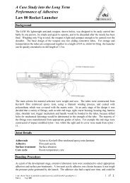
Assessment and Criticality <strong>of</strong> Defects & Damage in Materials SystemsCase Study: Composite overwrap repairs© 2003 AEA <strong>Technology</strong> plc
NDT Techniques - Composite RepairsTypes <strong>of</strong> damage in pipes• External corrosion• External damage - dents, gouges, axial or radial grooves,fretting at supports• Internal corrosion - general wall loss leading to leakageTypes <strong>of</strong> defects or damage in overwrapcomposite• Blisters• Delamination is defect <strong>of</strong> interest• Cracking• Entrapped air/ resin voids• Foreign matter• Pits, scores, surface porosity, wrinklesInspection Requirements• composite overwrap repair• surface and bond quality• underlying pipe
Assessment and Criticality <strong>of</strong> Defects & Damage in Materials SystemsNDT TechniquesVisualEddy CurrentAcoustic EmissionUltrasonicsThermographyLaser ShearographyInputs from MMS 15And Task 3
Assessment and Criticality <strong>of</strong> Defects & Damage in Materials SystemsIndustrially relevant - complex problemDefect assessment methodology usedfor composite repairs has beengeneralised to form basis forprocedures to be developed in MMS 13
Assessment and Criticality <strong>of</strong> Defects and Damage in Materials SystemsReview SummaryDefect types and acceptance criteria have been considered only formanufacturing defectsSeveral industrial guidelines & codes have been considered forassessing defects and and in-service damageAerospace industries implement comprehensive assessments fordamage toleranceRecent industrial guidelines (NORSOK & ISO 14692) cover in-servicedefects and acceptance criteria only on a simple basisNo formal guidance on in-service defect assessment procedures exists
http://materials.npl.co.uk/matsol/
Assessment and Criticality <strong>of</strong> Defects & Damage in Materials SystemsInformation SourcesConference Reports e.g. I Mech E, IoM, ECCM, ICCM, etc.Reference & Technical Literature AGARD, IACFA, ESA, NASAMIL-HDBK-17, ASM, etc.Standards BSI CEN ISO, ASME, ASTM, NORSOK, etc.In-house & published literaturePrevious & current DTI programmes, e.g MTS, CPD, DCC, MMS, etc.Current projects, e.g HOIS, ADM, etc.Internet/ S<strong>of</strong>twareIndustry/ Academic Contacts© 2003 AEA <strong>Technology</strong> plc
Task 2 – Experimental TestingCharacterisation <strong>of</strong> materialsM Gower and G Sims