engineering statement of technical requirements (sotr) -m8
engineering statement of technical requirements (sotr) -m8
engineering statement of technical requirements (sotr) -m8

You also want an ePaper? Increase the reach of your titles
YUMPU automatically turns print PDFs into web optimized ePapers that Google loves.
E V'00<br />
PE It- Pi SA1<br />
6JA^1^11^ JJ<br />
yam!<br />
"9 O"FCT OF<br />
2100N 0QG^'<br />
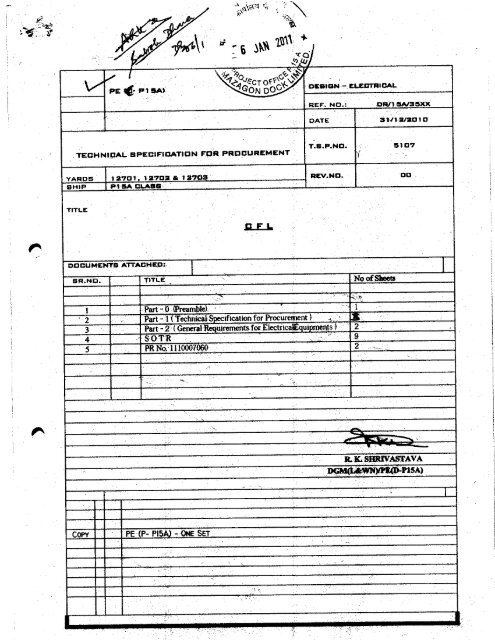
TECHNICAL SPECIFICATION FOR PROCUREMENT<br />
DESIGN - ELECTRICAL<br />
REF: ND,: DRM6A135XX<br />
DATE 31112/2D1D<br />
TS.P.ND.<br />
5107<br />
Y. -„'<br />
YARDS 12701 , 1272 & 1272 REV.ND . DD<br />
SHIP P1 5ACLASS ....`.-<br />
TITLE<br />
DOCUMENTS ATTACI4Ep--.<br />
Q FL<br />
SR,ND. TITLE No <strong>of</strong>Sheeta<br />
Copy<br />
I Part - 0 (Preamble) 1<br />
2 Part - 1Technical ificationfor Procurement )<br />
3 Part - 2 (General uirements for tiectrica ui eturtts) 2<br />
4 SOTR 9<br />
5 PR No. I 110007060 2<br />
PE (P- PIS - ONE SET<br />
it.K.SBRIVASTAVA<br />
DQ4I(#,^cyYNf lZ(U P15A)
M<br />
PART C PREAMBLE 1 :<br />
ESRNI6AL DEFMIFICAtION FOii pROCLRFA&Ent<br />
'p$<br />
PART I TECHNICAL 'SPECIFICATIS1 AND SOTR<br />
PART 2 GENERAL. REMENTS OF ELECTRICAL ESwIPMENT<br />
PART 5 PR NO, 1110007060<br />
AQON DOCK UMtE0<br />
MuMe/4i 400010.<br />
OESISN EISCTRICAL<br />
E:-" SPEC IJO..<br />
5107<br />
at)<br />
12/2010
PART OI<br />
01 INTRODUCTION<br />
010 Part 0<br />
This specification is written in two (2) parts:<br />
Preamble<br />
Oil Part I Technical Specification and SOTR<br />
012 Part 2 General Requirements <strong>of</strong> Electrical Equipments<br />
02 DEVIATION<br />
021 The supplier shotdd clearly indicate the clauses in the specification not being complied with. In the a bsence<br />
<strong>of</strong> a clew gaMWIPAC contrary. it will be assumed that the equipment A"WW wilt.nuel the requirement<br />
l<br />
d Inierai ltnquitements <strong>of</strong><br />
sin full, in case th a is Comotbetweenclause m roc unea s<br />
$lecvical Bgsuutnessft clause i Technical Specification shall cake pretence=<br />
022 T e supplier should not after the binding drawings or the scope <strong>of</strong> supply or any other aspect governed by<br />
this ponoct ' requis Lion as mall} agreed, without specific concurrence, f mm Ml3L , eves if any<br />
Clause<br />
Ir resident ' inspectors snacattaBCw^a a' uiG iii,w.<br />
Mecds the re9uirea<br />
Yes / No
1'<br />
, <strong>of</strong> Gam,<br />
tf<br />
-<br />
15 its" f,is; ^ 50 tt<br />
mw
Y^ 12701.127021 12703<br />
" acem?c Mft as1071ttv4<br />
Mumma<br />
(Part-1 ) S.ist 3 <strong>of</strong> 3<br />
8. GUARANTEE<br />
The manufacturer should give guarantee against poor pelforrrrarrcelbad<br />
workman ship<br />
for the period <strong>of</strong> 48 months from the date <strong>of</strong> delivery are 12 months from the date <strong>of</strong><br />
commissioning <strong>of</strong> the ship.<br />
PRODUCT SUPPORT<br />
The supplier should confirm product support for 10 years.<br />
10. ^f • °° •0 h. elial by a vendor with trehnkkat-hiler_<br />
a. A brief speeificationldescription <strong>of</strong> the equipment being <strong>of</strong>fered including a <strong>statement</strong><br />
showing anyway in which the equipment deviated from this TSP.<br />
b Operating supply voltage and frequency<br />
c. Wattage <strong>of</strong> lamp and lux<br />
d. Power factor<br />
e. Part number<br />
f Dirnentional details <strong>of</strong> CFL and weight<br />
g. Type <strong>of</strong> CFL ie. electronic or magnetic -ballast<br />
h. Colour ie. Daylight<br />
I<br />
PART - a<br />
(Psfl. t 1012<br />
ragNIERALI<br />
REDUtREMENTB OE ELECTRICAL EQUIPMENTS<br />
e / Item is generally required to withstand following . maritte conditions:<br />
Th<br />
Attdntatt termsera u Of-50 °C for Machinery Space and 45 °C at other places.<br />
t re<br />
h umid ty loo % at 35 °C, Seawater temperature 35 °C, Rol{.+1- 300P& S, pitch 0+/- 15°, list 20 °.<br />
2. All items must strictly conform to relevant drawings / specifications mentioned. in therequisitim<br />
3. General arrangement dr<br />
Gravity is to be supplied along with the <strong>of</strong>fer, for non-pattermseu ira<br />
awing &I 8 overall dimensions and approximate weight <strong>of</strong> the unit and center <strong>of</strong><br />
Wherever applicable, the production drawings are to be approvedby DQA / Statutory & regulatory agency- The<br />
manufacture <strong>of</strong>tbe itemsls tote started only on approval <strong>of</strong> the drawings. A ad <strong>of</strong> approvedprodwCtton<br />
.<br />
drawings is to be made avmleble to MDL for dimensions , faring details etc<br />
Whenever a pilot sample is required to be. manufactured, the lankproduction is to start only alter approval <strong>of</strong> the<br />
sample by inspecting Agarucy f MDL•<br />
6. No Component will be supplied by MDL<br />
7. The items an to be <strong>of</strong> robust construction so as to withstand adverse marine conditions. Similar parts are to be<br />
interchangeable The castings are to be fix from blowholes, sharp edges to be rounded <strong>of</strong>t the threads are to be<br />
oven and sharp . The switches, lamps, fuses, internal wires etc. used in 1te eg njnnent are to be either patternised<br />
ortype approved by'DQAI classification societies, as applicable. The details regarding this can be obtained from<br />
respective agencies. The indicating lamps should be easily accessible by unscrewing the lull's eye from the front.<br />
Fuses are to be clearly marked:<br />
8.<br />
,<br />
.shock /<br />
d) Lilting arrmtgememis to beprovided for heavy items.<br />
vibration<br />
a) The holes for mounting the equipment should be on hip outside the casing <strong>of</strong>the equipment<br />
b) :T a equipment lets be suitable forbulkhead! deck movnting.If equipment contains movableparts<br />
cowactaus or electronics assemblies etc. the equipment is m be antable for mounting on<br />
such as relaym<br />
Mw mounts we to be supplied Along with the equipment.<br />
c) Suitable earthingarrangement is to beprovided on the equipment.<br />
For Ship'<br />
s cables, the entries are to be through glands, unless otherwise stated The glands are to be as per<br />
specification DGS/EEDM/I5351K6, (For Naval Ships) I Standard Siemen's gland for Merchant Ships The<br />
gland mu and washers are to be left un chilled, unless specified.<br />
9. For connection <strong>of</strong> the ship's cables the terminals are to be easily accessible, For cables <strong>of</strong> sizes <strong>of</strong> 7/0,044 and<br />
higher, crimped sockets and clamp type terminals are to be provided for incoming & outgoing cable connection.<br />
block,<br />
the<br />
eating<br />
<strong>of</strong> n the equpment<br />
and the<br />
Aa apace should bemaw between terminals, tarannal<br />
cable entry glands:<br />
a. Internal wiring inthe panels to be <strong>of</strong> Low Fire Hazard cables.<br />
b The install n material , viz. free end connectors, cable ;maps, special tools if any,`mounts arc. to<br />
complete installation is to be supplied by you along with the equipment.<br />
10. The Part No. /The Pats. No. <strong>of</strong> each item is to beprominently and indelibly cast/ embossed ! tallied.
11. The following engraved tallies <strong>of</strong> brass I anodized aluminum are to be screwed on each equipment<br />
a. ManufCture's tally indicating name, description <strong>of</strong> the item, partlpatt. No,., rating, Sr. No., Year <strong>of</strong><br />
manufacture, weight etc.<br />
b. Functional tallies for switches, lamps, pushes etc.<br />
c. Danger tallies for equipment operating on 220 V andabove, the tally should have white letter on red<br />
d. Whore applicable 'MODWICfION STATE' <strong>of</strong> the equipment tally.<br />
e. Special tal Ies-to be provided as applicable viz. Circuit diagram tallies, operating instructions motor<br />
direction <strong>of</strong> rotation etc.<br />
12. The item is to be painted with admiralty ship's gray paint as per approved pang spec fication*ocedure.<br />
13. Minor modifications required by Owner/Inspecting Agencies / MUL are to be incorporated.<br />
14. For any deviations, however minor, prior approval is to be obtained from DQA (Navy) MDL Deviations<br />
once granted will not be icesaa&y applicable for repeat manufacture.<br />
15. Net weight <strong>of</strong> each item is to be recorded in the presence <strong>of</strong> the mapectorani a certificate to that effect is to be<br />
submittad-along with supplies:<br />
16. The equipment supplied by you will be installed on board the ship byMDL. The services <strong>of</strong> your engineers, if<br />
required during mstallatim setting to work, harbour trials, we trials, etc. to prove your eft to NAVY, be<br />
provided Your service engineers are to bring their own test equipments/toolsand spares for this purpose.<br />
- End Of Part 2
DIRECTORATE OF ELECTRICAL ENGINEERING<br />
STATEMENT OF TECHNICAL REQUIREMENTS (SOTR)<br />
-M8<br />
COMPACT FLUORESCENT LAMPS (CFCs)<br />
SUZTABLEFOR 23OVSUPPLV<br />
BPB<br />
P-17AND LSTR)<br />
SOTR NO. DEE101/04<br />
DATEOFISSUE: OCT O4<br />
IRtJ_°_ 68
a<br />
- 4<br />
STATEMENT OF TECHNICAL REOLOREMENTSISOTR)<br />
Mg<br />
P-17AND LSTIL)<br />
1. Scope. The <strong>statement</strong> <strong>of</strong> <strong>requirements</strong> covers the design , construction , testing<br />
methods and conditions for lighting system luminaries including CFLs with integrated<br />
means for controlling, starting and stable operation (Self Ballasted Lamps) to be fitted<br />
onboard Naval ships . The design, shape & size <strong>of</strong> the CFIs should be compatible to<br />
existing GLS luminaries (with B22/PP) fitted onboard ships and catered for trouble free<br />
operation under the most adverse environmental and marine conditions . The CFLs<br />
should conform to IS 15111 (Part I &II)- 2002 for safety and performance<br />
<strong>requirements</strong>.<br />
2. Pgrom. The purpose <strong>of</strong> CFLs is to provide lighting <strong>of</strong> requisite luminosity<br />
onboard Naval ships. The CFIs will be used in lieu <strong>of</strong> incandescent lamps in non-CAT<br />
`N compartments onboard ships.<br />
3. wattage <strong>of</strong> CFLs. The CFLs <strong>of</strong> following ratings equivalent to incandescent<br />
lamps will be used onboard IN ships . The wattage should be marked on the lamps.<br />
Wattage <strong>of</strong> Incandescent Lamps Eauivalent Wattage <strong>of</strong> CFLs<br />
40 W 11W<br />
60 W 15-1.91=.<br />
100W 20W<br />
4. Supply Voltage. The CFLs should be designed for 230V 50Hz Ph supply. The<br />
voltage or the voltage range should be marked on the lamp deary.<br />
4.1 Input AC Supply Characteristics. The input AC supply characteristics shall be as<br />
per table given below:-<br />
CHARACTERISiIC DESCRIPTION VALUE<br />
Nominal Voltage 230V<br />
Load range tolerance Line to Line ±5%<br />
Constant Load Tolerance + 1%<br />
Maximum Modulation Transients 2%<br />
(Excluding Spikes)<br />
Frequent Transients -10% to + 6%<br />
Voltage Recovery Time 0.5 Sec<br />
Infrequent Transients -16% to + 10%<br />
Recovery Time 1 Sec<br />
Frequency Nominal Frequency 50 Hz
I<br />
5. Technical Reauireme ts.<br />
5.1 Qnstrixtion. The CFL casing shall be made <strong>of</strong> cast aluminum alloy (A6M) with<br />
suitable glass covering . The enclosure <strong>of</strong> CFI- should be <strong>of</strong> splash pro<strong>of</strong> (IP 55)<br />
construction providing adequate protection against ingress <strong>of</strong> moisture and dust.<br />
All electronic components , lamp holder and reflector etc. should be <strong>of</strong> standard<br />
manufacturer and be mounted on single PCB . However the transformer should<br />
be secured Inside the casing. The panel cover should be secured with captive<br />
screws with lock-in-nuts.<br />
5.2 r mq lity <strong>of</strong> CFL vis-h-vis Lamp Fitinos. The details are as follows:-<br />
CFLs (EL Type) CFI- Length in mm Compatible Lamp Fittings<br />
which are already<br />
Remarks<br />
Min Max<br />
Pattemised<br />
20 W 140 155 Patt No . 0581/923-7422<br />
Patt No. 0581/923-5751<br />
Patt No . 0581/923-5752<br />
To be used with<br />
large type lamp<br />
fittings as per BR<br />
320 D<br />
15 W 106 125 Patt No . 0581/923-5758 To be used with<br />
small type lamp<br />
fittings as per BR<br />
320 D<br />
11 W 120 142 Patt No. 0581/923-7421 To be used only<br />
for lighting<br />
bathroom/cabin<br />
mirrors.<br />
5.3 Mane urerer's Technical S flcation. The manufacturer 's <strong>technical</strong><br />
specification <strong>of</strong> the above CFLs Is shown In Appendix 'A'
I<br />
6. Tests.<br />
6.1 Classification <strong>of</strong> Tests<br />
6.2 TYce Test. The type tests to be carried out on selected samples <strong>of</strong> self ballasted<br />
lamps would be as per IS 15111 Part I and II . The details are given in<br />
succeeding paragraphs:-<br />
As per IS 15111 Part I<br />
6.2.1 Marking . The lamps shall be clearly and durably marked with the following<br />
mandatory markings:-<br />
(a) Mark <strong>of</strong> origin (this may take the form <strong>of</strong> a trade-mark, the manufacturers<br />
name or the name <strong>of</strong> the responsible vendor);<br />
(b) Rated voltage or the voltage range (marked 'V' or 'Volts);<br />
(c) Rated wattage (marked 'W' or 'Watts');<br />
(d) Rated Frequency (marked in 'Hz');<br />
(e) Rated luminous flux;<br />
(f) Rated colour temperature; and<br />
(g) Country <strong>of</strong> manufacture.<br />
6.2.1.1 The durability <strong>of</strong> the marking Is checked by trying to remove it by rubbing lightly<br />
for 15 seconds with a piece <strong>of</strong> loth soaked with water and, after drying, for a<br />
further 15 seconds with a piece <strong>of</strong> dotty soaked with hexane. The marking shall<br />
be legible after the test.<br />
6.2.2 Interchangeability. Compliance <strong>of</strong> combination <strong>of</strong> cap and bulb Is checked by<br />
the use <strong>of</strong> gauges for checking the dimensions controlling interchangeability in<br />
accordance with IS 9206:<br />
6.2.3 . Test finger shall not touch live parts in normal<br />
use when applied In all directions with force <strong>of</strong> 10 N.<br />
6.2.4 Insulation -Resistance and Electric Strength after Humidly Treatment. The<br />
lamps shall be conditioned for 48 hours in a cabinet containing air with a relative<br />
humidity between 91 % and 95%. The tempe rature <strong>of</strong> the air Is maintained<br />
within 1°C <strong>of</strong> any convenient value between 20t and 30°C.
6.2.4.1 Insulation resistance shall be measured in the humidity cabinet with a dc<br />
voltage <strong>of</strong> approximately 500V . One minute after application <strong>of</strong> the voltage, the<br />
insulation resistance between current-carrying metal parts <strong>of</strong> the cap and<br />
accessible parts <strong>of</strong> the lamp (assessable parts <strong>of</strong> the insulating material are<br />
covered with metal foil) shall be not less than 4 MO.<br />
6.2.4.2 The insulation resistance <strong>of</strong> B 22 caps between shell and contact shall be not<br />
less than 5 Mfg.<br />
6.2.5 Mechanical Strength. The cap shall be subjected to the torque by means <strong>of</strong> the<br />
torsion test holder. The torque shall not apply suddenly, but shall be increased<br />
continuously from 0 to the specified value . The Lamp should withstand minimum<br />
3.0 Nm <strong>of</strong> mechanical strength.<br />
6.2.6 Cap Temperature Rise. The cap temperature rise tests <strong>of</strong> the complete lamp<br />
during run-up, stabilization period and after stabilization shall not exceed the<br />
value mentioned below:-<br />
For B 22d ........................ 125 K<br />
6.2.7 Resistance to Heat . External part <strong>of</strong> insulating material <strong>of</strong> self ballasted lamp<br />
shall be sufficiently resistant to heat . The test is made in a heating cabinet for a<br />
sufficient time to ensure that they have attained the stabilized testing<br />
temperature before the test commences . The surface <strong>of</strong> the part to be tested is<br />
placed in the horizontal position and a steel ball <strong>of</strong> 5 mm diameter pressed<br />
against this surface with a force <strong>of</strong> 20 N . After ball pressure test the diameter <strong>of</strong><br />
impression shall not exceed 2 mm.<br />
6.2.8 Resistance to Rame Ignition . External parts <strong>of</strong> the insulating material retaining<br />
n live parts in position and external parts <strong>of</strong> insulating material providing protection<br />
against electric shock are subjected to the glow wire test at 650°C.<br />
6.2.9 Fault Condition . Lamps shall not impair safety when operating under following<br />
fault conditions:<br />
(a) Short circuit in starter.<br />
(b) Short circuit across capacitors.<br />
(c) Broken cathode.<br />
(d) De-activated lamp.
OPN<br />
/1^<br />
(e) open circuit<br />
LOAD Part_II<br />
The lamp dimension shall comply with the <strong>requirements</strong> as<br />
6.2.10 rement agency.<br />
indicated by the procu<br />
6.2.11 c+°, and Run-up. The lamp shall fully light up and remain alight within 4.0<br />
seconds at 92% <strong>of</strong> rated voltage. The time to reach 80% <strong>of</strong> the Initial lumen<br />
characteristics shall not exceed 120 sec.<br />
6.2.12 yamo Wati• The initial wattage dissipated by the lamp shall not differ by<br />
mote than + 15% and -10%.<br />
1I uMMULElux. Initial lumen flux after the ageing time shall not be less than<br />
and the<br />
6.2.13 90% <strong>of</strong> the rated luminousthe colour P specified in the standard).<br />
efficacy corresponding<br />
6.2.14 I r• The colour Coordinated <strong>of</strong> a lamp shall be within the tolerance area on<br />
the chromaticity chart<br />
wer Factor. The power factor <strong>of</strong> the combination <strong>of</strong> the ballast and the lamp<br />
6.2.15 Po<br />
shall not be less than 0.80.<br />
Lift.<br />
The average life <strong>of</strong> lamp shall not be less than 6000 hrs.<br />
6.2.17 Lamp Effic W. The efficacy <strong>of</strong> the lamp will be as given in the table 2 <strong>of</strong> IS<br />
15111 (Part II).<br />
After 2000 h <strong>of</strong> operation inducting the aging period, the<br />
6.2.18 Lumen Maintenance .<br />
shall be not less than 90% <strong>of</strong> the initial luminous<br />
iumen m<br />
characteristics.<br />
6.3 ^+nta^ Test The acceptance tests would include the above<br />
tests at<br />
6.2.1 to 6 .2.6 and 6S<br />
1 tox6 2.1 . In addition, CFLs will be subjected<br />
vibration test as per<br />
The CFLs should meet EMI/EMC <strong>requirements</strong> onboard ships as per IEC<br />
7. FWIEM<br />
OEM will provide EMI/EMC Test report The CFLs have been cleared to be used<br />
1547. dth i hail room storage spy.<br />
in non-CAT' A' com r i.e. i, n n<br />
a ys etc-onboard ships.<br />
8. Nnsoe Linn<br />
A oritY. DQA(N) would be the inspection authority.
9. Procurement. The following information be provided to the<br />
manufacturer/vendor at the time <strong>of</strong> the procurement <strong>of</strong> CFL: -<br />
(a) Operating Supply (in terms <strong>of</strong> voltage and frequency)<br />
(b) Wattage <strong>of</strong> lamp<br />
(c) Power factor<br />
(d) Part No.<br />
(e) Dimensional details <strong>of</strong> CFL.<br />
(f) Type <strong>of</strong> CFL (with electronic or magnetic ballast)<br />
(g) Colour (Day light/Warm white/Blue/Red)<br />
10. Related Documents and Acceptable Standards.<br />
SOCICWWAMOFIS Titles<br />
IS 15111 (Part I &II ) (2002) - Self ballasted lamps for general lighting<br />
services.<br />
Part I - Safety <strong>requirements</strong>.<br />
Part II- Performance <strong>requirements</strong>.<br />
IS 1258 (1987) - Bayonet lamp holders.<br />
IS 8913 (1978) - Methods <strong>of</strong> measurement <strong>of</strong> lamp cap<br />
temperature rise.<br />
IS 9206 (1979) - Dimensions <strong>of</strong> caps for tungsten filament GLS<br />
lamps.<br />
IS 11000 (Part II/Sec 1x1988) - Fire hazard testing.<br />
Part H - Test methods<br />
Section 1- Glow wire test and guidance<br />
IS 6873 (Part 5)(1999) - Methods <strong>of</strong> measurement <strong>of</strong> electromagnetic<br />
interference<br />
Part 5 - Florescent lamps and luminaries.
IS 2592 (1980) - Vibration tests.<br />
NES 587 - Requirements for lighting system.<br />
EED-Q- 261 - Specification for light fittings<br />
BR 320 D - Catalogue <strong>of</strong> Naval Stores (pass Group 0581)
APPENDDC `A'<br />
Lamp Related Data ELD-11WI ED-15W ELT-20W Remarks<br />
Working Voltage 230V Voltage to<br />
(V)<br />
Working Frequency 50 Hz<br />
(HZ)<br />
Rated light output 2700 K 600 900 1200<br />
(Base up) (Im) 4000 K 600 900 1200<br />
6500 K 565 850 - 1 1120<br />
Colour Temperature 2700, 4000,6500<br />
2700 K 55 55 60<br />
Efficacy (Im/W) 4000 K 54 54 59<br />
6500 K 51 51 56<br />
Lamps caps B-22d<br />
Lamp current(A): 0.080 0.100 0.140<br />
(Input)<br />
Maximum starting < 4 Second<br />
time mS<br />
Starting Voltage 170<br />
Nominal Power 11 1 15 20<br />
Lamp Power (W) + 15% - 10% (As per BIS)<br />
(Tolerance)<br />
Lumen Maintenance 85 (As per BIS)<br />
(100 + 2000h ) %<br />
Lumen Maintenance 70 (As per OG)<br />
(2000 + 6000h) (%)<br />
Frequemy (kHz) >20<br />
We (with-W 6000 hrs (As per BIS)<br />
operation) 165 min<br />
ON AS Min <strong>of</strong>f Hrs<br />
Burning Position Universal<br />
Applicable Torque 3.0 NM<br />
cap (8-22d/E-27)<br />
Warm-up time after<br />
switch ON<br />
-80% <strong>of</strong> light output 120 Max<br />
(S)<br />
-100%<strong>of</strong> light output 300<br />
S<br />
Max cap 129C<br />
temperature rise °C<br />
Min Starting 140V<br />
V Pnwar Fartnr n Rn<br />
be<br />
spedflecl