

2. Perforation device - Tambula Textilmaschinenteile GmbH
2. Perforation device - Tambula Textilmaschinenteile GmbH
2. Perforation device - Tambula Textilmaschinenteile GmbH

Create successful ePaper yourself
Turn your PDF publications into a flip-book with our unique Google optimized e-Paper software.
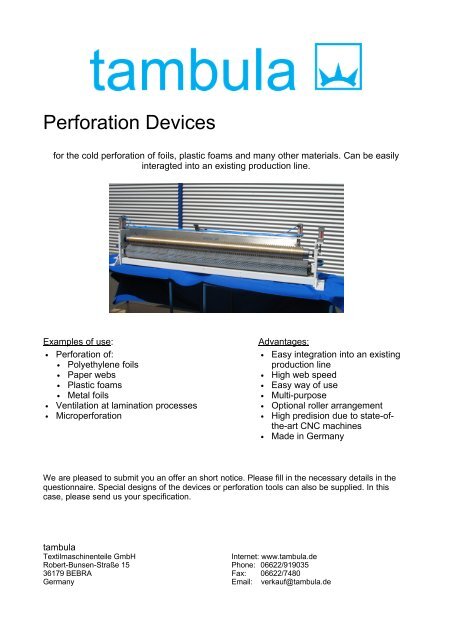
<strong>Perforation</strong> Devices<br />
for the cold perforation of foils, plastic foams and many other materials. Can be easily<br />
interagted into an existing production line.<br />
Examples of use: Advantages:<br />
• <strong>Perforation</strong> of:<br />
• Polyethylene foils<br />
• Paper webs<br />
• Plastic foams<br />
• Metal foils<br />
• Ventilation at lamination processes<br />
• Microperforation<br />
• Easy integration into an existing<br />
production line<br />
• High web speed<br />
• Easy way of use<br />
• Multi-purpose<br />
• Optional roller arrangement<br />
• High predision due to state-ofthe-art<br />
CNC machines<br />
• Made in Germany<br />
We are pleased to submit you an offer an short notice. Please fill in the necessary details in the<br />
questionnaire. Special designs of the <strong>device</strong>s or perforation tools can also be supplied. In this<br />
case, please send us your specification.<br />
tambula<br />
<strong>Textilmaschinenteile</strong> <strong>GmbH</strong> Internet: www.tambula.de<br />
Robert-Bunsen-Straße 15 Phone: 06622/919035<br />
36179 BEBRA Fax: 06622/7480<br />
Germany Email: verkauf@tambula.de
Description:<br />
• The <strong>device</strong> is basically intended for the cold perforation process.<br />
• The correct penetration depth is adjusted via adjusting screws.<br />
• After the adjustment of the correct penetration depth by the adjusting screws, the top<br />
roller is actuated either manually, pneumatically with hand lever valve or electropneumatically<br />
with remote control.<br />
• The <strong>device</strong> does not include any maintenance unit, as the pressure air can be normally<br />
taken from the system.<br />
• The support shafts can be exchanged according to the material guiding (see <strong>2.</strong>1).<br />
• Mounting brackets for the fitting at the machine are available.<br />
• The <strong>device</strong> will be adjusted accordingly if the fastening ponits are specified.<br />
Questionnaire:<br />
Please mark the desired version with a cross and fill in the form completely. If there are any questions<br />
concerning the desired spiked or counter rollers please feel free to contact us and/or to send us a sample of<br />
your material for testing purposes.<br />
1. Purpose of use<br />
Material to be processed: (z.B.: HDPE)<br />
Material thickness: (µm, mm)<br />
Working width of material: (mm)<br />
(Working width of <strong>device</strong> = working width of material + 100mm)<br />
Product speed: (m/min)<br />
Type of machine:<br />
<strong>2.</strong> <strong>Perforation</strong> <strong>device</strong><br />
<strong>2.</strong>1 Material guiding:<br />
(The material to be perforated should always be guided over the counter roller)<br />
� Spiked roller up (sketch A)<br />
α: , β:<br />
� Counter roller up (sketch B)<br />
α: , β:<br />
2
<strong>2.</strong>2 Lowering of the roller:<br />
� Manually<br />
• Push rod clamping <strong>device</strong> for lowering the roller manually<br />
• Fine adjustment with adjusting screws<br />
� Remote controlled<br />
• Pneumatically actuated cylinders<br />
• Fine adjustment by adjusting screws<br />
Control by:<br />
� Hand lever valve<br />
� Solenoid valve (please specify the voltage)<br />
<strong>2.</strong>3 Shock-proof protection:<br />
� Cover plates or hood<br />
• Not essential if integrated into an existing production line<br />
• Protects from unintentional contact with the spiked rollers<br />
• You must comply with the valid safety instructions when using the <strong>device</strong><br />
• Please fill in under (<strong>2.</strong>1) web guiding and angle<br />
<strong>2.</strong>4 Possibilities of transport:<br />
� Bracket handles<br />
• Not essential<br />
• Facilitates the manual transport (for lightweight <strong>device</strong>s) or the application of transport<br />
material<br />
� Ring nuts (ISO 582 M10)<br />
• Not essential<br />
• Facilitates the application of transport material<br />
3
<strong>2.</strong>5 Support shaft material:<br />
� Steel<br />
• Cheaper option<br />
• Heavy construction<br />
� Aluminum<br />
• Optional: Light construction<br />
<strong>2.</strong>6 Surface structure of the counter roller:<br />
� Brushes<br />
• According to the material suited for coarser till fine pins (T > 5mm)<br />
• By choosing a balanced brush-counterroller there is always a steelshaft installed<br />
� Felt<br />
• Suited for fine pins<br />
� Grooved aluminum / steel<br />
• The grooves have been directly worked into the steel or aluminum counter roller<br />
• The pins run in the grooves<br />
• Suited e. g. for harder material which is to be perforated<br />
• Possible from pitch 5 mm (in rows), or from 10mm (staggered)<br />
� PU-coated<br />
• Necessary for microperforation<br />
• Suited for very fine pins or for very small hole diameters<br />
4
<strong>2.</strong>7 Balancing of rollers:<br />
� Balancing of support shafts<br />
• From the following web speeds and working widths (AB) balancing is advisable:<br />
AB: 500mm-1500mm 95m/min (300 rpm) AB: 1600mm-2000mm 120m/min (300 rpm)<br />
<strong>2.</strong>8<br />
Color of the <strong>device</strong>:<br />
� Standard color: Blue (RAL 5010)<br />
� Special color as required:<br />
<strong>2.</strong>9<br />
Working width (AB) and standard mounting dimensions:<br />
5
3. Pin Segments<br />
3.1<br />
Dimensions of the standard pin segments:<br />
(Dimensions in mm)<br />
Unstaggered pins (A) Staggered pins (B)<br />
Density T W F PinØ Density T W F PinØ<br />
� 16 pins/cm² 2,5 2,5 3,85 0,99 � 16 pins/cm² 2,5 2,5 3,85 0,99<br />
� 4 pins/cm² 5 5 3,85 0,99 � 4 pins/cm² 5 5 3,85 0,99<br />
� 1 pins/cm² 10 10 5,5 1,63 � 1 pins/cm² 10 10 5,5 1,63<br />
� 0,25 pins/cm² 20 20 10 2,62 � 0,25 pins/cm² 20 20 10 2,62<br />
(pinØ = maximum diameter at the pin shank)<br />
� Customer request<br />
• We will be pleased to offer upon request any individual pin arrangements of the segments according to<br />
your specification.<br />
• In this case please fill in our “Questionnaire Spiked Rollers” or send us a drawing.<br />
• Please note that the outer diameters of the support shafts at the following working widths (AB) are as<br />
follows:<br />
AB: (500mm – 1500mm) Di= ø80 mm AB: (1600mm – 2000mm) Di= ø110 mm<br />
6
3.2<br />
Core material of the standard segments:<br />
� Without core<br />
• The roundness is not as accurate as with core<br />
• Low-cost version from AB 1600 or coarse pins (0.25 pin/cm²)<br />
• Attachment between clamping disks<br />
� Steel core<br />
• Cheaper than aluminum core<br />
• Heavy construction<br />
� Aluminum core<br />
• Light construction<br />
• Also suited for high product speeds<br />
3.3<br />
Attachment of the standard pin segments:<br />
� Setscrews<br />
• Standard version<br />
• Any roller is attached separately at the support shaft<br />
• Serves as axial (displace) and radial (turn) fixing<br />
• In connection with a notched support shaft, a correct pin arrangement can be<br />
reached<br />
• Only up to a pitch of T>10 mm (0.25 N/cm², 1 N/cm²). At a smaller pitch the<br />
pins are omitted at the screw connection.<br />
• Is necessary for movable single segments at partial perforation<br />
� Tensed between clamping disks<br />
• Manual alignment of the pin segments<br />
• The segments are tensed by clamping disks which are attached at the front of<br />
the support shafts. In this way the segments are protected from axial and<br />
radial displacement<br />
• Only necessary for fine pins (16 pins/cm²) and segments without core<br />
� Front studs<br />
• Special equipment<br />
• The spiked rollers are put together and they are correctly aligned by the studs.<br />
• For the axial fixing 2 additional edge segments are necessary. These<br />
segments are attached by clamping screws at the support shaft.<br />
7
tambula<br />
<strong>Textilmaschinenteile</strong> <strong>GmbH</strong> Internet: www.tambula.de<br />
Robert-Bunsen-Straße 15 Telefon: 06622/919035<br />
36179 BEBRA Telefax: 06622/7480<br />
Germany Email: verkauf@tambula.de