RS82 VHF System Radio - Simrad Professional Series
RS82 VHF System Radio - Simrad Professional Series
RS82 VHF System Radio - Simrad Professional Series

You also want an ePaper? Increase the reach of your titles
YUMPU automatically turns print PDFs into web optimized ePapers that Google loves.
MAXIMIZING YOUR PERFORMANCE AT SEA
Instruction manualM A N U A L<strong>Simrad</strong> RS81/<strong>RS82</strong><strong>VHF</strong> <strong>Radio</strong> <strong>System</strong>III
RS81/<strong>RS82</strong> <strong>VHF</strong>© 2004 <strong>Simrad</strong> LtdThe technical data, information and illustrations contained in this publication were to the best of our knowledgecorrect at the time of going to print. We reserve the right to change specifications, equipment, installation and maintenanceinstructions without notice as part of our policy of continuous development and improvement.No part of this publication may be reproduced, stored in a retrieval system or transmitted in any form, electronic orotherwise without prior permission from <strong>Simrad</strong> Ltd.No liability can be accepted for any inaccuracies or omissions in the publication, although every care has been taken tomake it as complete and accurate as possible.IV Part no. E04572 Issue E 26/04/04 CR
Instruction manualC O N T E N T SPart I – INTRODUCTION1 GENERAL1.1 Introduction . . . . . . . . . . . . . . . . . . . . . . . . . . . . . . . . . . . . . . . . . . . .111.1.1 About this manual . . . . . . . . . . . . . . . . . . . . . . . . . . . . . . . . .121.2 Licensing . . . . . . . . . . . . . . . . . . . . . . . . . . . . . . . . . . . . . . . . . . . . . .131.3 MMSI number . . . . . . . . . . . . . . . . . . . . . . . . . . . . . . . . . . . . . . . . . .141.4 Group ID MMSI . . . . . . . . . . . . . . . . . . . . . . . . . . . . . . . . . . . . . . . . .141.5 ATIS number . . . . . . . . . . . . . . . . . . . . . . . . . . . . . . . . . . . . . . . . . . .14Part II – THE RS81 <strong>VHF</strong> RADIO SYSTEM2 INTRODUCTION3 MAIN FUNCTIONS3.1 General notes . . . . . . . . . . . . . . . . . . . . . . . . . . . . . . . . . . . . . . . . . . .173.2 Switching the radio on & off . . . . . . . . . . . . . . . . . . . . . . . . . . . . . .183.3 Second country modes . . . . . . . . . . . . . . . . . . . . . . . . . . . . . . . . . . .183.4 Changing channels . . . . . . . . . . . . . . . . . . . . . . . . . . . . . . . . . . . . . .193.4.1 Channel sets . . . . . . . . . . . . . . . . . . . . . . . . . . . . . . . . . . . . . .193.5 Volume . . . . . . . . . . . . . . . . . . . . . . . . . . . . . . . . . . . . . . . . . . . . . . . .203.6 Squelch . . . . . . . . . . . . . . . . . . . . . . . . . . . . . . . . . . . . . . . . . . . . . . . .203.7 Speaker mute . . . . . . . . . . . . . . . . . . . . . . . . . . . . . . . . . . . . . . . . . . .213.8 Dual Watch mode . . . . . . . . . . . . . . . . . . . . . . . . . . . . . . . . . . . . . . .213.9 Triple Watch or Tri-Watch mode . . . . . . . . . . . . . . . . . . . . . . . . . . .223.10 All scan mode . . . . . . . . . . . . . . . . . . . . . . . . . . . . . . . . . . . . . . . . .223.10.1 Dynamic All scan inhibit . . . . . . . . . . . . . . . . . . . . . . . . . . .233.11 Memory scan mode . . . . . . . . . . . . . . . . . . . . . . . . . . . . . . . . . . . . .233.11.1 Dynamic Memory scan delete . . . . . . . . . . . . . . . . . . . . . . .243.12 Adjusting backlighting . . . . . . . . . . . . . . . . . . . . . . . . . . . . . . . . . .243.13 Handset off cradle . . . . . . . . . . . . . . . . . . . . . . . . . . . . . . . . . . . . . .244 MENU MODE4.1 Scanning . . . . . . . . . . . . . . . . . . . . . . . . . . . . . . . . . . . . . . . . . . . . . . .254.1.1 All scan inhibit . . . . . . . . . . . . . . . . . . . . . . . . . . . . . . . . . . . .254.1.2 All scan reset . . . . . . . . . . . . . . . . . . . . . . . . . . . . . . . . . . . . . .264.1.3 All scan show . . . . . . . . . . . . . . . . . . . . . . . . . . . . . . . . . . . . .264.1.4 Memory scan select . . . . . . . . . . . . . . . . . . . . . . . . . . . . . . . .264.1.5 Memory scan clear . . . . . . . . . . . . . . . . . . . . . . . . . . . . . . . . .274.1.6 Memory scan show . . . . . . . . . . . . . . . . . . . . . . . . . . . . . . . . .274.1.7 Scan dwell time . . . . . . . . . . . . . . . . . . . . . . . . . . . . . . . . . . . .274.2 Numbers . . . . . . . . . . . . . . . . . . . . . . . . . . . . . . . . . . . . . . . . . . . . . . .284.2.1 Ship’s MMSI . . . . . . . . . . . . . . . . . . . . . . . . . . . . . . . . . . . . . .284.2.2 ATIS number . . . . . . . . . . . . . . . . . . . . . . . . . . . . . . . . . . . . . .294.3 <strong>VHF</strong> Items . . . . . . . . . . . . . . . . . . . . . . . . . . . . . . . . . . . . . . . . . . . . .314.3.1 User channel . . . . . . . . . . . . . . . . . . . . . . . . . . . . . . . . . . . . . .314.3.2 Last used channel . . . . . . . . . . . . . . . . . . . . . . . . . . . . . . . . . .32E04572V
Instruction manual8 MENU MODE8.1 Scanning . . . . . . . . . . . . . . . . . . . . . . . . . . . . . . . . . . . . . . . . . . . . . . .528.1.1 All scan inhibit . . . . . . . . . . . . . . . . . . . . . . . . . . . . . . . . . . . .528.1.2 All scan reset . . . . . . . . . . . . . . . . . . . . . . . . . . . . . . . . . . . . . .538.1.3 All scan show . . . . . . . . . . . . . . . . . . . . . . . . . . . . . . . . . . . . .538.1.4 Memory scan select . . . . . . . . . . . . . . . . . . . . . . . . . . . . . . . .538.1.5 Memory scan clear . . . . . . . . . . . . . . . . . . . . . . . . . . . . . . . . .548.1.6 Memory scan show . . . . . . . . . . . . . . . . . . . . . . . . . . . . . . . . .558.1.7 Scan dwell time . . . . . . . . . . . . . . . . . . . . . . . . . . . . . . . . . . . .558.2 Numbers . . . . . . . . . . . . . . . . . . . . . . . . . . . . . . . . . . . . . . . . . . . . . . .558.2.1 Ship’s MMSI . . . . . . . . . . . . . . . . . . . . . . . . . . . . . . . . . . . . . .568.2.2 Group MMSI . . . . . . . . . . . . . . . . . . . . . . . . . . . . . . . . . . . . . .568.2.3 ATIS number . . . . . . . . . . . . . . . . . . . . . . . . . . . . . . . . . . . . . .578.3 <strong>VHF</strong> Items . . . . . . . . . . . . . . . . . . . . . . . . . . . . . . . . . . . . . . . . . . . . .588.3.1 User channel . . . . . . . . . . . . . . . . . . . . . . . . . . . . . . . . . . . . . .588.3.2 Position view . . . . . . . . . . . . . . . . . . . . . . . . . . . . . . . . . . . . . .598.3.3 Last used channel . . . . . . . . . . . . . . . . . . . . . . . . . . . . . . . . . .608.3.4 Interrupt intercom . . . . . . . . . . . . . . . . . . . . . . . . . . . . . . . . .608.3.5 Speaker settings . . . . . . . . . . . . . . . . . . . . . . . . . . . . . . . . . . .608.3.6 SimNet management . . . . . . . . . . . . . . . . . . . . . . . . . . . . . . .618.3.6.1 Data sources . . . . . . . . . . . . . . . . . . . . . . . . . . . . . . . .628.3.6.2 Lighting banks . . . . . . . . . . . . . . . . . . . . . . . . . . . . . .638.3.6.3 Device instance . . . . . . . . . . . . . . . . . . . . . . . . . . . . . .648.3.6.4 <strong>System</strong> instance . . . . . . . . . . . . . . . . . . . . . . . . . . . . .658.3.7 Lighting modes . . . . . . . . . . . . . . . . . . . . . . . . . . . . . . . . . . . .669 DSC FUNCTIONS9.1 General . . . . . . . . . . . . . . . . . . . . . . . . . . . . . . . . . . . . . . . . . . . . . . . .679.2 Making a call . . . . . . . . . . . . . . . . . . . . . . . . . . . . . . . . . . . . . . . . . . .679.2.1 Individual routine call . . . . . . . . . . . . . . . . . . . . . . . . . . . . . .679.2.2 Public correspondence call . . . . . . . . . . . . . . . . . . . . . . . . . . .689.2.3 All Ships Safety call . . . . . . . . . . . . . . . . . . . . . . . . . . . . . . . .709.2.4 All Ships Urgency call . . . . . . . . . . . . . . . . . . . . . . . . . . . . . .709.2.5 Group call . . . . . . . . . . . . . . . . . . . . . . . . . . . . . . . . . . . . . . . .719.2.6 Distress Alert call . . . . . . . . . . . . . . . . . . . . . . . . . . . . . . . . . .719.3 Receiving a call . . . . . . . . . . . . . . . . . . . . . . . . . . . . . . . . . . . . . . . . .739.3.1 Individual routine call . . . . . . . . . . . . . . . . . . . . . . . . . . . . . .739.3.2 Public correspondence call . . . . . . . . . . . . . . . . . . . . . . . . . . .749.3.3 All Ships Safety call . . . . . . . . . . . . . . . . . . . . . . . . . . . . . . . .759.3.4 All Ships Urgency call . . . . . . . . . . . . . . . . . . . . . . . . . . . . . .759.3.5 Group call . . . . . . . . . . . . . . . . . . . . . . . . . . . . . . . . . . . . . . . .769.3.6 Distress Alert call . . . . . . . . . . . . . . . . . . . . . . . . . . . . . . . . . .779.3.7 Distress Alert acknowledgement . . . . . . . . . . . . . . . . . . . . . .789.3.8 Distress Relay call . . . . . . . . . . . . . . . . . . . . . . . . . . . . . . . . . .799.4 Viewing the call log . . . . . . . . . . . . . . . . . . . . . . . . . . . . . . . . . . . . . .809.5 Position over 4 hours old . . . . . . . . . . . . . . . . . . . . . . . . . . . . . . . . .8110 THE DIRECTORY10.1 Switching between the directories . . . . . . . . . . . . . . . . . . . . . . . . .8210.2 Viewing the directory . . . . . . . . . . . . . . . . . . . . . . . . . . . . . . . . . . .82VII
RS81/<strong>RS82</strong> <strong>VHF</strong>10.3 Entering a number . . . . . . . . . . . . . . . . . . . . . . . . . . . . . . . . . . . . . .8310.4 Editing a number . . . . . . . . . . . . . . . . . . . . . . . . . . . . . . . . . . . . . . .8411 MISCELLANEOUS FUNCTIONS11.1 Selecting Weather Watch . . . . . . . . . . . . . . . . . . . . . . . . . . . . . . . . .8511.1.1 Weather Watch alert . . . . . . . . . . . . . . . . . . . . . . . . . . . . . . .8511.2 Security mode (voice scrambler) . . . . . . . . . . . . . . . . . . . . . . . . . .8611.3 Losing SimNet data . . . . . . . . . . . . . . . . . . . . . . . . . . . . . . . . . . . . .8611.4 Losing NMEA data . . . . . . . . . . . . . . . . . . . . . . . . . . . . . . . . . . . . .8711.5 Editing Latitude, Longitude and UTC . . . . . . . . . . . . . . . . . . . . . .8711.6 Toggling between Lat/Long and UTC views . . . . . . . . . . . . . . . .8911.7 Intercom . . . . . . . . . . . . . . . . . . . . . . . . . . . . . . . . . . . . . . . . . . . . . .8911.7.1 Making an intercom call . . . . . . . . . . . . . . . . . . . . . . . . . . . .8911.7.2 Receiving an intercom call . . . . . . . . . . . . . . . . . . . . . . . . . .9011.8 Station speaker mute . . . . . . . . . . . . . . . . . . . . . . . . . . . . . . . . . . . .9011.9 iDSC . . . . . . . . . . . . . . . . . . . . . . . . . . . . . . . . . . . . . . . . . . . . . . . . .91Part IV – INSTALLATION12 INSTALLATION12.1 Physical installation . . . . . . . . . . . . . . . . . . . . . . . . . . . . . . . . . . . . .9512.1.1 Transceiver installation . . . . . . . . . . . . . . . . . . . . . . . . . . . . .9512.1.2 Handset installation . . . . . . . . . . . . . . . . . . . . . . . . . . . . . . .9612.1.3 Station speaker installation . . . . . . . . . . . . . . . . . . . . . . . . .9712.2 Electronic installation . . . . . . . . . . . . . . . . . . . . . . . . . . . . . . . . . . .9712.2.1 Handset . . . . . . . . . . . . . . . . . . . . . . . . . . . . . . . . . . . . . . . . .9812.2.2 Loudspeakers . . . . . . . . . . . . . . . . . . . . . . . . . . . . . . . . . . . .9912.2.3 NMEA0183 input . . . . . . . . . . . . . . . . . . . . . . . . . . . . . . . . .10012.2.5 SimNet connectors . . . . . . . . . . . . . . . . . . . . . . . . . . . . . . . .10012.2.6 Summary . . . . . . . . . . . . . . . . . . . . . . . . . . . . . . . . . . . . . . . .10112.2.7 Cable strain relief . . . . . . . . . . . . . . . . . . . . . . . . . . . . . . . . .10112.3 Antenna installation . . . . . . . . . . . . . . . . . . . . . . . . . . . . . . . . . . . .10212.4 Electrical interference suppression . . . . . . . . . . . . . . . . . . . . . . . . .10413 FURTHER INFORMATION13.1 Operating procedures . . . . . . . . . . . . . . . . . . . . . . . . . . . . . . . . . . .10513.1.1 Sending a Distress Alert . . . . . . . . . . . . . . . . . . . . . . . . . . . .10513.1.2 Acknowledging and relaying a Distress Alert call . . . . . . .10513.1.3 Cancelling a Distress Alert . . . . . . . . . . . . . . . . . . . . . . . . . .10613.1.4 Alerting all vessels within range . . . . . . . . . . . . . . . . . . . . .10613.1.5 Calling a coast radio station . . . . . . . . . . . . . . . . . . . . . . . . .10613.1.6 Making an intership call . . . . . . . . . . . . . . . . . . . . . . . . . . . .10613.2 NMEA sentences received . . . . . . . . . . . . . . . . . . . . . . . . . . . . . . .10613.3 Transmission range . . . . . . . . . . . . . . . . . . . . . . . . . . . . . . . . . . . . .10713.4 Frequency of channels . . . . . . . . . . . . . . . . . . . . . . . . . . . . . . . . . . .10813.5 Troubleshooting . . . . . . . . . . . . . . . . . . . . . . . . . . . . . . . . . . . . . . . .10913.6 Dimensions . . . . . . . . . . . . . . . . . . . . . . . . . . . . . . . . . . . . . . . . . . .11013.7 Technical specification . . . . . . . . . . . . . . . . . . . . . . . . . . . . . . . . . . .11113.8 Accessories & spares . . . . . . . . . . . . . . . . . . . . . . . . . . . . . . . . . . . .11113.9 Service & Warranty . . . . . . . . . . . . . . . . . . . . . . . . . . . . . . . . . . . . .11213.10 Declaration of Conformity . . . . . . . . . . . . . . . . . . . . . . . . . . . . . .113VIIIE04572
PART IINTRODUCTION
RS81/<strong>RS82</strong> <strong>VHF</strong>The AHS81 and AHS82 have been designed with simple operationin mind for ease of use, even in installations that have onestation of each type. The handsets are fully waterproof anddesigned for all environments from the navigation station tothe open cockpit.1.1.1 About this manualThis manual combines operating and installation informationon both the RS81 and <strong>RS82</strong> and is divided into four main parts.As the handsets have differing layouts and functions areaccessed in different ways, we recommend that you familiariseyourself with the information pertaining to the product thatyou have purchased prior to installation or use. This will facilitatefull understanding of the many operating features andensure straightforward installation.Thank you for choosing <strong>Simrad</strong>.If you are pleased with your <strong>VHF</strong> radio, we hope you will beinterested in our range of marine electronic equipment, whichis manufactured to the same high standards as the RS81/<strong>RS82</strong>.Please contact your nearest <strong>Simrad</strong> agent for a catalogue showingour increasing range of high-tech navigational instruments,GPS, Autopilots, Radar, Echosounders, Chartplotters and <strong>VHF</strong>radio sets.<strong>Simrad</strong> operates a policy of continual development and reservethe right to alter and improve the specification of their productswithout notice.12 E04572
Instruction manual1.2 LicensingNOTEPrior to use please check the national licensing requirementsfor operators.In the UK licence applications and queries should be made tothe following authority:Ship <strong>Radio</strong> Licensing<strong>Radio</strong> Licencing CentreThe Post OfficePO Box 1495BristolBS99 3QSWebsite: www.radiolicencecentre.co.uk/rlcA set may only be operated by or under the supervision of theholder of a Marine <strong>Radio</strong> Operator’s Certificate of Competenceand Authority to Operate. This is awarded on completion of theMarine Short Range Certificate course administered by the RoyalYachting Association:Royal Yachting AssociationRYA HouseEnsign WayHambleSouthamptonSO31 4YAWebsite: www.rya.org.ukTel. 0845 345 0400Holders of the Restricted Certificate of Competence in <strong>Radio</strong>telephony(which covers MF/HF SSB, etc.) do not need a separate<strong>VHF</strong> certificate.In all other countries, please contact your regional authority forinformation.E0457213
RS81/<strong>RS82</strong> <strong>VHF</strong>1.3 MMSI numberAt the time of issue of your vessel’s radio licence, an MMSI(Maritime Mobile Service Identity) number must be requested toenable the operation of DSC functions. This is a nine-digitnumber, which must be permanently entered into the <strong>RS82</strong>, orRS81 with the DSC-capable AHS82 handset fitted.NOTEIf the boat, or the RS81 or <strong>RS82</strong>, is subsequently sold, the radiomust be returned to an authorised <strong>Simrad</strong> agent for the MMSInumber to be erased and the new owner’s MMSI numberentered.An MMSI number will only be issued to licensed and certifiedusers. Please enquire with your local licensing authority forfull details.Please refer to section 4.2.1 (RS81) or section 8.2.1 (<strong>RS82</strong>) forinformation on how to enter the vessel’s MMSI number.1.4 Group ID MMSIFor boats that are part of a flotilla, racing fleet or other group,a Group ID MMSI number can also be entered, which willallow DSC communication within the group, if DSC is available.NOTEContact your local authority for rules regarding Group MMSInumber allocation.Please refer to section 8.2.2 for information on how to enter aGroup MMSI number. Please note, that the Group MMSI numberfunction is not available on the AHS81 handset.1.5 ATIS numberSome countries require an ATIS number (e.g. Benelux and theRhine/Danube waterways); however, this option will onlyappear on ATIS-equipped radios.Please refer to section 4.2.2 (RS81) or section 8.2.3 (<strong>RS82</strong>) forinformation on how to enter the ATIS number.14 E04572
PART IITHERS81 <strong>VHF</strong> RADIO SYSTEM
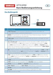
DIMMERInstruction manual2 INTRODUCTIONSIMRADThe RS81 is a modular <strong>VHF</strong> radio system with a user friendly,remote-style handset to access and control all functions.The RS81 transceiver “black box” is robustly constructedusing a pressure die-cast aluminium case for effective heatdissipation, ensuring maximum transmission performanceeven after many hours constant use.ON/CMENUWX WATCHSCAN ALL SCAN MSIMRAD AHS81VOLSQLINTSPKRSHIFTUSEROK1W D/W 16AHS81 handsetThe dual station RS81 radio system has been designed forcountries in which DSC capability is not a requirement. It isideal for leisure and light commercial use and can support upto two handsets. Additional stations can either be anotherAHS81-type handset, or a DSC-capable, fully-featured AHS82radio-telephone handset. The RS81 offers full intercom facilityand allows optional geographical position input via NMEA(if the second handset is an AHS82).The operation of the AHS81 handset, which has an inbuiltloudspeaker, is designed to be simple and intuitive. Largebuttons and a rubber-profiled handle-back ensure safe andcomfortable handling, whilst the large, backlit LCD allowseasy reading, even in difficult conditions.The handset is tough and waterproof, and is designed towithstand the rigours of the marine environment.3 MAIN FUNCTIONS3.1 General notesPacked with many advanced features, the Dual Station RS81 iscompact and has a contemporary look and feel.The SHIFT key is used to access secondary functions printed insmall letters below the main function on the key – simply pressSHIFT, then select the appropriate key. Secondary functions areshown in this manual in brackets, e.g. (SCAN M).NOTEThe SHIFT key will time out of Shift mode after 2 seconds, ifanother key is not pressed.The handset plugged into Station 1 is the master controller.Operations initiated on this handset will override all other stations.When a handset is lifted off its cradle, the other handsetwill display “OCCUPIED”. If a press and hold operation is initiatedon a handset, the other will display “IN USE” and functionswill not be accessible.When entering or editing text in any of the displays, the cursorposition is indicated by a flashing dash.E0457217
RS81/<strong>RS82</strong> <strong>VHF</strong>3.2 Switching the radio on & offTo switch the radio on, press and hold the ON/C key. For 2 secondsthe display will show the handset's software issue number,then for 2 seconds the station number followed by the lastchannel used (see section 4.3.2).When turning on the radio for the first time, all settings will displayat default values, including the channel setting, which is setto the priority channel (normally 16). When turned on, the radiowill revert to previously stored volume and squelch settings.To switch the radio off, press and hold the ON/C key for 2 seconds.The display screen will go blank and any audio will bemuted to indicate that the unit has been turned off.3.3 Second country modesIn countries where it is permitted, the RS81 can operate on asecondary set of channels, such as the USA channels.To enter the Second country mode press SHIFT followed by OK.The display will show the second country for 2 seconds, thenreset. The current mode is displayed in the top left-hand corner(cf. Fig 3.1).NOTESecond country modes are linked to specific primary countrymodes:PrimaryInternational, “INT”USA, “USA”River (Rhine), “RIVER”Canadian, “CAN”SecondaryUSA, “USA”International, “INT”International, “INT”USA, “USA”NOTEIf the primary country mode is Canadian, an optional tertiarycountry mode from “CAN” to either “USA”, or “INT” becomesavailable.18 E04572
Instruction manual3.4 Changing channelsTo select a channel, use the ▼ and ▲ keys to scroll through theavailable channels and view their associated functions (Fig 3.1).The priority channel (normally 16) can be selected by pressing16, which will always set the radio to high 25W transmitpower.INT16INT72VOLUME 05VOLUME 05Fig 3.1 - Selecting a channelThe User channel is preset and can be directly accessed bypressing the USER key. A “U” next to the channel number willindicate that it has been set as the User channel (Fig 3.2).23INTUVOLUME 04Fig 3.2 - User channel selectedNOTE The default for the User channel is 16.NOTE Selecting 16 at any point will revert the unit to channel 16,which is the default mode, and high power. This is a safetyfeature.If a channel is selected using a press and hold operation, otherhandsets will not update, until the key has been released (cf.section 3.1).3.4.1 Channel setsIn addition to the standard international channel, the RS81 canbe programmed with a range of auxiliary channels, such as theMarina channel in the UK, the USA Weather channels and theScandinavian Fishing and Leisure channels.E0457219
RS81/<strong>RS82</strong> <strong>VHF</strong>Use the ▲ and ▼ keys to choose a channel fromthe preset range (Fig 3.3).INTM2MAR I NAAAAAMAR I NAAAAAPR I VATE AAAFig 3.3 - Selecting auxiliary channel sets(sets must be available to be displayed)3.5 VolumePress the VOL key to enter the volume adjustment mode,then use the ▲ and ▼ keys to adjust the volume from 1 to 24(loud).The volume adjustment mode will time out after 2 seconds ifno key is pressed. If either the ▲ or ▼ key is held pressed, themode will cycle through the settings until released.3.6 SquelchPress the SQ key to enter squelch mode, then use the ▲ and▼ keys to determine the setting between 1 and 10. If either the▲ or ▼ key is pressed continuously, the mode will cyclethrough the levels.To cancel press the OK or ON/C key, otherwise the mode willtime out after 2 seconds.20 E04572
Instruction manual3.7 Speaker muteTo mute/unmute the handset’s integral speaker and earpiecewhilst the handset is on the cradle, press the SHIFT followed byVOL (SPKR) to toggle between mute (the display will show“SPKR MUTED”) and unmute (the display will show “VOL-UME XX”).Pressing and holding SHIFT, as well as pressing VOL (SPKR) –when the handset is on the cradle – will control whether thespeaker is muted when the handset is removed from the cradle.The display will show “CRD MUTE Y” (for “Yes”) to confirmthe setting, repeat the above procedure to unmute the speaker.3.8 Dual Watch modeDual Watch allows the radio to scan between the selectedworking channel and the watch channel (the priority channel,usually 16).To enter Dual Watch mode press D/W – the display will showthe working channel in large digits with the watch channel displayedbeneath (Fig 3.4).INT6DWD/W AAAA 16BBBBBBBBBBFig 3.4 - Dual Watch modeIf the handset is not on the cradle, it will display “CRADLE”and the Dual Watch mode will terminate after 10 seconds,unless the handset is replaced.When the radio detects a signal on the Watch channel, it willlock onto this and the large digits will change to show theWatch channel number.To cancel Dual Watch lift the handset from the cradle, or pressON/C or 16.NOTE Dual Watch cannot be initiated if the radio is on channel 16.E0457221
RS81/<strong>RS82</strong> <strong>VHF</strong>3.9 Triple Watch or Tri-Watch modeThe Triple or Tri-Watch function allows the radio to scanbetween the selected working channel, the User channel andthe Watch channel (the priority channel, usually 16).To enter Triple Watch mode, press and hold the D/W key for 2seconds – the display will show the working channel in largedigits with the Watch and User channels displayed in smallerdigits below (Fig 3.5).INT10T/W16U23Fig 3.5 - Tri-Watch modeIf the handset is not on the cradle, it will display “CRADLE”and the Tri-Watch mode will terminate after 10 seconds, unlessthe handset is replaced.When the radio detects a signal on the Watch or the User channel,it will lock onto this and the large digits will change toshow the respective channel number.To cancel Tri-Watch, lift the handset from the cradle, or pressON/C or 16.NOTETri-Watch cannot be initiated, if the radio is on channel 16 orthe User channel, or if channel 16 has been programmed to bethe User channel.3.10 All scan modeIn the scan function the RS81 will cycle sequentially througheach enabled channel, pausing every time a signal is detected.To enter All scan mode, press SHIFT followed by 1W (SCAN ALL).Two LCD segments will circle the screen to indicate that scanningis in progress (Fig 3.6, p. 23).If the radio locks onto a channel, press OK to continue the scan,or wait until the signal becomes clear. If scanning is initiatedand the handset is not on the cradle, it will display “CRADLE”.Scanning will time out after 10 seconds and not start, until thehandset has been replaced.22 E04572
Instruction manualINT06SHIFTSCANALLINT--SCANALLFig 3.6 - All scan modeTo cancel lift the handset, alternatively press ON/C or 16. Thedisplay will show the last channel scanned.3.10.1 Dynamic All scan inhibitIf the radio repeatedly locks onto the same busy channel, thiscan be excluded from the scan by pressing SHIFT then 1W(SCAN ALL) while locked on that channel.“INHIBITED” will be displayed for 2 seconds, after which thescan will resume whilst excluding the inhibited channel. Toreset inhibited channels, please refer to sections 4.1.1 and 4.1.2.3.11 Memory scan modeMemory scan allows scanning of a pre-programmed set ofchannels specified by the user (see also sections 4.1.4 and 4.1.5).To enter Memory scan mode, press SHIFT followed by D/W(SCAN M). Two LCD segments will now circle the screen toindicate that scanning is in progress (Fig 3.7). If the radio locksonto a channel, press OK to continue the scan, or wait until thesignal becomes clear.INT06SHIFTSCANMINT--SCANMFig 3.7 - Memory scan modeE0457223
RS81/<strong>RS82</strong> <strong>VHF</strong>If scanning is initiated and the handset is not on the cradle, itwill display “CRADLE”. Scanning will not start until the handsethas been replaced and time out after 10 seconds.To cancel the scanning function lift the handset, alternativelypress ON/C or 16. The display will show the last channelscanned.3.11.1 Dynamic Memory scan deleteIf the radio repeatedly locks onto the same busy channel, thiscan be removed from the Memory scan process by pressingSHIFT and D/W (SCAN M) while locked on that channel.“INHIBITED” will be displayed for two seconds (Fig 3.8), afterwhich the scan will resume bypassing the inhibited channel. Toreset inhibited channels, please refer to section 4.1.4.INT68SCANMINHIBITEDFig 3.8 - Memory scan delete3.12 Adjusting backlightingThe display and keypad are backlit – to set the backlightinglevel, press SHIFT followed by ON/C.There are six levels of lighting: “OFF”, and 1 (bright) to 5 – usethe ▲ and ▼ keys to adjust the brightness. The mode will timeout after 2 seconds, but can also be cancelled by pressing eitherthe ON/C or OK key.3.13 Handset off cradleThe RS81 can support up to two handsets. If either is lifted ofthe cradle, the other will display “OCCUPIED”, unless aresponse to a station-to-station intercom call is required.NOTEIf the master controller displays “OCCUPIED”, it will automaticallybecome active when lifted, as its operation overrides allother handsets. The other handset will be locked out and willnow display “OCCUPIED” instead.24 E04572
Instruction manual4 MENU MODEMenu mode is used to adjust the various radio settings, such aschannels inhibited from scan modes, ID number programmingand User channel selection.To enter menu mode, press SHIFT twice. Use the ▲ and ▼ keysto scroll through the options listed below:• Scanning (section 4.1) covers options related to the variousscanning functions such as channel inhibit, memoryscan select and scan dwell time.• Numbers (section 4.2) explains how to enter ID numberssuch as the Ship’s MMSI and ATIS number.• <strong>VHF</strong> Items (section 4.3) describes miscellaneous optionssuch as selection of a User channel, last used channel, interruptintercom and speaker settings.To select an option press OK, to return to normal radio operationpress ON/C.NOTEEntering menu mode will inhibit the operation of the radio.Exit menu mode before returning the handset to the cradle topermit normal operation.4.1 ScanningIn the Menu mode select Scanning by pressing OK, using the ▲and ▼ keys to scroll through the following options:• All scan inhibit (section 4.1.1)• All scan reset (section 4.1.2)• All scan show (section 4.1.3)• Memory scan select (section 4.1.4)• Memory scan clear (section 4.1.5)• Memory scan show (section 4.1.6)• Scan dwell time (section 4.1.7)To select an option press OK, to return to the main menu pressON/C.4.1.1 All scan inhibitIf the radio is repeatedly locking onto a busy channel whenscanning, this channel can be excluded from the scan cycle.Each option will be displayed for 2 seconds.In Scanning mode press OK, then use the ▲ and ▼ keys to scrolland select the “ALL INH” option, which will be displayed for 2seconds. Press OK again, then use the ▲ and ▼ keys to selectthe channel to be excluded, or, if the channel has been inhibitedE0457225
RS81/<strong>RS82</strong> <strong>VHF</strong>(the display will show “INHIBITED”), the channel to be reenabled(Fig 4.1). Press OK to confirm each setting.INT65ALLAI NH BFig 4.1 - Selected channel inhibited from scanPress ON/C to return to the Scanning menu.4.1.2 All scan resetIn the Scanning menu press the OK key to enter the submenu,then use the ▲ and ▼ keys to select “ALL RESET”. Now pressOK to reset all inhibited channels. The display will show“RESETTING” for 2 seconds, then “ALL RESET” (Fig 4.2).ALL RESETEBFig 4.2 - All inhibited channels resetPress ON/C to return to the main mode, or use the ▲ and ▼keys to select another option.4.1.3 All scan showThis Scanning mode function will display all inhibited channels.In Scanning mode press OK and use the ▲ and ▼ keys toselect “ALL SHOW”. Press OK again and the display willchange, “SHOWING” all inhibited channels in sequence.Press ON/C to return to the main menu, or use the ▲ and ▼keys to select another option.NOTEIf private or auxiliary channels have been omitted from scanning,the “SHOWING” function will display them after thenormal channels that have been excluded from scanning.4.1.4 Memory scan selectThis function selects the channels to be used in the Memoryscan cycle (see section 3.10).In Scanning mode press OK to enter the submenu and use the▲ and ▼ keys to select “MEM SEL”, which will be displayed26 E04572
Instruction manualfor 2 seconds. Press OK, then use the ▲ and ▼ keys to choosethe desired channel and press OK to add the channel to thememory scan, or to delete a previously selected channel (thedisplay will show “ENABLED” for each selected channel).Use the above procedure to select/deselect further channels, orpress the ON/C key to return to the main scanning mode.NOTENorth American users: only one Weather channel can be addedto the Memory scan, if another one is selected, it will overridethe existing channel. The Weather channel will not be scannedas part of the Memory scan sequence, but used by the WeatherWatch function instead (cf. section 5.1).4.1.5 Memory scan clearMemory scan clear will remove all channels previously includedin the Memory scan.Press OK to access the scanning submenu and use the ▲ and ▼keys to select “MEM CLEAR” (Fig 4.3). Press OK to reset all theinhibited channels. The display will show “CLEARING” for 2seconds.MEM CLEARBBFig 4.3 - Selecting channel for memory scanUse the ▲ and ▼ keys to choose another option, or press ON/Cto return to the main menu.4.1.6 Memory scan showThis function displays all channels selected for Memory scan.Press OK to access the Scanning submenu and use the ▲ and ▼keys to select “MEM SHOW”. The display will sequentiallyshow all channels selected for memory scan.To exit this submenu press OK, or use the ▲ and ▼ keys tochoose another option.4.1.7 Scan dwell timeThis function is used to select the length of time the RS81remains on a channel after it has locked onto it during eitherthe All scan, or Memory scan function.From the Scanning menu press OK to access the submenus anduse the ▲ and ▼ keys to select “DWELL”. There are 11 levels ofdwell time from 0–10 (seconds).E0457227
RS81/<strong>RS82</strong> <strong>VHF</strong>To adjust the dwell time setting, press OK to enter the editmode and use the ▲ and ▼ keys to select the desired scandwell time. The display will show “XX SECONDS” (with “XX”denoting the new dwell time) for 2 seconds, then return to“DWELL” showing the new level (Fig 4.4).DWELL 04Fig 4.4 - Scan dwell timePress OK to exit the submenus, or the ▲ and ▼ keys to choose afurther option.4.2 NumbersThe Numbers menu is used to enter ID numbers such as theMMSI (Maritime Mobile Service Identity) or ATIS numbers (thelatter is applicable only in certain countries), please refer also tosections 1.3 and 1.5 of the introduction.Once the Numbers menu option has been selected (see introductionto section 4), use the ▲ and ▼ keys to scroll through thefollowing menu options:• Ship’s MMSI (section 4.2.1)• ATIS number (section 4.2.2)NOTEThe ATIS number option will only be shown if the radio isATIS enabled. This feature is only available for sets used in theBenelux and Rhine/Danube waterways.To select an option, press OK. To return to the main menu,press ON/C.NOTE4.2.1 Ship’s MMSIThis option is only available in systems with an AHS82 connected(please refer also to section 1.3).The Ship’s MMSI function will display the boat’s MMSI numberonce it has been entered, or will allow the MMSI number tobe entered when the radio is being used for the first time.From the Numbers menu (section 4.2) press OK to enter thesubmenu and select “SHIPS MMSI”. After 2 seconds the numberwill be displayed – if it has not been entered yet, the displaywill show dashes only (“- - -”), with a flashing dash indicatingthe cursor position (Fig 4.5, p. 29).28 E04572
Instruction manualINT16i1234 - - - - -Fig 4.5 - Entering the MMSI numberTo enter the nine-digit MMSI number, use the ▲ and ▼ keys toscroll and select the number required. Use the VOL and SQkeys to correct any errors and press OK when entry is completed.The radio will now display “CONFIRM” and the MMSInumber must be re-entered. If the two numbers do not match,the above procedure must be repeated.NOTECAUTIONThe MMSI number will not be accepted, unless all nine digitshave been entered; the suffix “0” is automatically inserted bythe radio.The MMSI number can only be entered once and cannot be editedby the user. Should it become necessary to change the MMSInumber (e.g. if the radio is being moved to another boat), theradio must be sent to an authorised <strong>Simrad</strong> service agent forreprogramming.Press ON/C to return to the Numbers menu.NOTE4.2.2 ATIS numberThis section applies only to radios used in countries where theATIS system is in operation (Benelux and the Rhine/Danubewaterways). This option will only appear on ATIS-equippedradios (see also section 1.5).From the Numbers menu select “ATIS NO” – the display willshow the ATIS number, unless the number has not beenentered yet, in which case the display will show dashes only,with a flashing dash indicating the cursor position (“- - -”).Enter the nine-digit ATIS number using the ▲ and ▼ keys andthe VOL and SQ keys to correct any errors.Press OK when entry is completed and re-enter the numberwhen prompted by the radio (“CONFIRM”, Fig 4.6, p. 30). If thetwo numbers do not match, the procedure must be repeated.E0457229
RS81/<strong>RS82</strong> <strong>VHF</strong>INT16CONFIRMFig 4.6 - Entering the ATIS numberNOTECAUTIONThe ATIS number will not be accepted, unless all nine digitshave been entered – the prefix “9” is automatically inserted bythe radio.The ATIS number can only be entered once and cannot be editedby the user. Should it become necessary to change the ATISnumber, the radio must be sent to an authorised <strong>Simrad</strong> serviceagent for reprogramming.Press ON/C to return to the Numbers menu.30 E04572
Instruction manual4.3 <strong>VHF</strong> ItemsThe <strong>VHF</strong> Items menu contains the settings for miscellaneousitems such as User channel, voice scrambling, lighting andspeaker settings.Once the <strong>VHF</strong> Items menu option has been selected (section 4),use the ▲ and ▼ keys to scroll through the menu optionsbelow:• User channel (section 4.3.1)• Last used channel (section 4.3.2)• Interrupt intercom (section 4.3.3)• Speaker settings (section 4.3.4)• Lighting modes (section 4.3.5)• SimNet (section 4.3.6)• Serial number (section 4.3.7)To select an option press OK, or press ON/C to return to themain menu.4.3.1 User channelThis is a user-programmable priority channel, which is used inthe Tri-Watch function and is selected by pressing the USER key.In the <strong>VHF</strong> Items menu press OK to enter the submenus anduse the ▲ and ▼ keys to select “USER CH”. Press the OK keyagain to edit the User channel and use the ▲ and ▼ keys toscroll to the desired channel. Press OK again to confirm, thedisplay will show “SETTING” for 2 seconds (Fig 4.7).INT10SETTINGBBFig 4.7 - Setting the User channelPress ON/C to return to the <strong>VHF</strong> Items menu.E0457231
RS81/<strong>RS82</strong> <strong>VHF</strong>4.3.2 Last used channelNormally, the RS81 will power up on the pre-programmedstart-up channel (usually the priority channel). The Last usedchannel function enables the radio to power up on the last usedchannel (the default setting is ”OFF”).Press OK to enter the <strong>VHF</strong> Items submenu and use the ▲ and ▼keys to select “LST CH", which will show either “Y[es]”, or“N[o]”. Use the OK key to toggle between “Y” and “N”.Press ON/C to exit the submenu, or use the ▲ and ▼ keys toselect another option.4.3.3 Interrupt intercomThis function is used to specify whether intercom functionsshould be interrupted when an incoming <strong>VHF</strong> transmission isreceived.Press OK to enter the <strong>VHF</strong> Items submenu and use the ▲ and ▼keys to select “INT ICM Y” – note that the default setting is“Y[es]”. Use the OK key to toggle between “Y” and “N”.Press ON/C to exit the submenu, or use the ▲ and ▼ keys toselect another option.4.3.4 Speaker settingsThe speaker settings option is used to set the individual defaultvolume levels for each station and/or intercom in the system.Press OK to enter the <strong>VHF</strong> Items submenu and use the ▲ and ▼keys to select “SET SPKRS”, then press OK again to enter thespeaker settings menu, the display will show “DEFAULTS”(Fig 4.8). Use the ▲ and ▼ keys to choose “STATION 1” or“STATION 2”, then press OK to confirm.INT16INT16SET SPKRS00DEFAULTS00NOTEFig 4.8 - Resetting speaker settings to defaultsThis menu has a wrap-around function.Press ON/C to exit, or use the ▲ and ▼ keys to select anotheroption.32 E04572
Instruction manual4.3.4.1 Setting up speakersSpeaker levels can be reset by pressing OK to select “SET SPKRS”in the <strong>VHF</strong> Items submenu. Press OK to access the speaker settingssubmenu and use the ▲ and ▼ keys to select “DEFAULTS”(see Fig 4.8 above).Press OK to reset all speaker settings to default. The displaywill show “RESETTING” for 2 seconds.Press ON/C to exit this menu level, or use the ▲ and ▼ keys toselect another option.4.3.4.2 Adjusting independent volumesTo set speakers’ volume levels independently, select “SETSPKRS” in the <strong>VHF</strong> Items submenu. Press OK to enter thespeaker settings submenu and use the ▲ and ▼ keys to select astation (e.g. “STATION 1”).Press OK to initiate independent volume adjustment (see section3.5 for available settings). The radio will now emit a continuous500Hz tone via the selected speaker. Adjust the volumelevel using the ▲ and ▼ keys and press OK to confirm the newsetting, which will be displayed and end the tone.Press ON/C to exit this menu level, or use the ▲ and ▼ keys toselect another option.4.3.5 Lighting modesThe lighting mode allows adjustment of the level of lighting forthe station, the radio or the whole of the network. The chosenmode can also be stored in separate banks for each individualstation connected to the radio.In the <strong>VHF</strong> Items menu select OK to enter the submenu anduse the ▲ and ▼ keys to select ”LIGHTING”, press OK again.Use the ▲ and ▼ keys to select either “STATION”, “RADIO” or“NETWORK” and press OK. The display will show “SEL STN”,“SEL RADIO” and “SEL NET”, respectively, to confirm thechoice. These displays will be shown for 2 seconds.The selected lighting mode will be stored and available whenthe radio is turned on next time.E0457233
RS81/<strong>RS82</strong> <strong>VHF</strong>4.3.6 SimNetSimNet is <strong>Simrad</strong>’s proprietary network bus system. Note, thatthe SimNet functions detailed below are handset specific.From the <strong>VHF</strong> Items menu press OK to enter the submenusand select “SIMNET” pressing OK again. Use the ▲ and ▼ keysto select one of the following menu options: “BANK SEL” (section4.3.6.1), “DEVICE INS” (section 4.3.6.2) or “SYSTEM INS”(section 4.3.6.3).Press ON/C to exit return to the upper menu level.4.3.6.1 Banks selectTo edit the light banks select “BANKS” from the SimNet mode,then press OK. Use the ▲ and ▼ keys to select a station andpress OK to edit the required bank.Then using the ▲ and ▼ keys scroll through to the requiredbank and press OK to select it. The display will show“SELECTED” for 2 seconds, then return to show the stationnumber.Press ON/C to return to the upper menu levels.4.3.6.2 Device instanceFor multiple systems, this function allocates a number to aradio when there are more than one of the same products onthe network.From the SimNet menu press OK to enter the submenus anduse the ▲ and ▼ keys to select “DEVICE INS”. Press OK toenter the editing mode (the default number is “000”), then usethe ▲ and ▼ keys to allocate a number and press OK to confirm.“SELECT XXX” (where “XXX” is the chosen number) willbe shown for 2 seconds (Fig 4.9).INT▼▲16NO.001BFig 4.9 - Allocating a device number to one of several identicaldevices on the same network34 E04572
Instruction manual4.3.6.3 <strong>System</strong> instanceFor large boats, this function allocates a number to the radioon a network when there is more than one network.From the SimNet menu press OK to enter the submenus anduse the ▲ and ▼ keys to select “SYSTEM INS”. Press OK toenter the editing mode (the default number is “00”), then usethe ▲ and ▼ keys to allocate a network number (Fig 4.10) andpress OK to confirm. The radio will show “SELECT XX”(where “XX” is the chosen number) for 2 seconds.INT▼▲16NO.02BFig 4.10 - Allocating a number to a device wherethere are several networks4.3.7 Serial numberThe radio’s serial number can be found under the <strong>VHF</strong> Itemsmenu. From within the <strong>VHF</strong> Items menu press OK and use the▲ and ▼ keys to select “SERIAL NO”, which will display thenumber for 2 seconds.Press ON/C to return to the upper menu level, or use the ▲ and▼ keys to select another option.E0457235
RS81/<strong>RS82</strong> <strong>VHF</strong>5 MISCELLANEOUS FUNCTIONS5.1 Selecting Weather WatchThe Weather Watch function enables the radio to monitor a singleWeather channel specified in the memory scan select function(see section 4.1.4). A transmission on a Weather channel ispreceded by a tone – if it is detected by the radio, it will triggeran alert to allow the user to switch to the Weather channel.To enable Weather Watch, press the SHIFT key followed by theUSER (WX WATCH) key to display the Weather channel (Fig 5.1).WX12WATCHBBBW4Fig 5.1 - Selecting Weather Watch modeIf a weather channel has not been selected for inclusion in amemory scan, the display will show “NO WX CHAN”, beforereturning to the upper menu level. Likewise, if Weather Watchis not enabled the display will show “NO WX MODE” for 2seconds before returning to the upper menu level.For instructions on how to select a Weather channel refer tosection 4.1.4.To cancel Weather Watch, repeat pressing the SHIFT key followedby the USER (WX WATCH) key. The display will show“CANCEL WX” for 2 seconds before returning to the uppermenu level.5.1.1 Weather Watch alertIf the radio detects a weather alert tone on the specified Weatherchannel, it will sound a 10-second alarm and the display willshow “WX ALERT”.Press OK to cancel the alarm and switch to the selected Weatherchannel. To ignore the weather alert, press ON/C or wait untilthe alarm times out.To return to the working channel press ON/C. Note, that thiswill not cancel the Weather Watch mode (cf. section 5.1 above).36 E04572
Instruction manual5.2 Security mode (voice scrambler)For additional security, a voice scrambler function is availableas an optional accessory. The scrambler uses frequency inversionto encrypt the transmission and will allow secure transmissionbetween compatible radios. (See also section 4.3.6.)To enter security mode, press SHIFT followed by 16. The displaywill show “NO SCRM”, if the scrambler function is not enabledin the system. If security mode is enabled, the display willshow “SEC” in the top left-hand corner of the LCD.To exit press SHIFT followed by 16 again, or ON/C.5.3 Losing NMEA dataNMEA data may be processed by the Dual Station RS81, inorder to transmit the boat’s position if a Distress Alert is initiated.Note, that this is only possible if the second handset installed isan AHS82.One minute after NMEA data is lost, the station speakers willsound an alarm and the display will show “NMEA LOST”,until the operator confirms the warning by pressing either theON/C or the OK key.5.4 IntercomIf the system has two handsets connected, it is possible to makean intercom call from one handset to the other.5.4.1 Making an intercom callPress SHIFT followed by the SQ key to enter intercom mode.The display will show “SHIFT”, then “INTERCOM” (Fig 5.2).INT12I N T ERCOMA BFig 5.2 - Making an intercom callPress OK, or use the PTT key to initiate intercom mode. Thiswill trigger the intercom alarm.E0457237
RS81/<strong>RS82</strong> <strong>VHF</strong>NOTENOTENOTEOnce initiated the OK key can be used to re-sound the alarm ifrequired. Further pressing of the PTT key will open the audiopath to the receiving station to allow voice calling.If a call is not answered within 15 seconds, the call will time out.If interrupt intercom is enabled and radio traffic is received,the intercom will be suspended and the received audio transmissionwill be routed to the station speakers (PTT must bedisabled at this point). Once radio traffic has ceased, the intercomcall will continue.If interrupt intercom is disabled and the squelch is open, thedisplay will show “RX SIGNAL”, until the squelch is closed(Fig 5.3).INT12RX SIGNAL BFig 5.3 - Interrupt intercom disabledTo end an intercom call, press ON/C, or replace the handset.5.4.2 Receiving an intercom callWhen an intercom call is received from another station, thehandset display will show “INTERCOM”.5.5 Received DSC call displaysPlease note that DSC call displays will only be shown, if the secondhandset connected to the radio is an AHS82. These displays are warningsonly, calls cannot be acknowledged or cancelled from the AHS81.5.5.1 Individual callINT24VOLUME 10INT24INDIVIDUALFig 5.4 - Receiving an individual call38 E04572
Instruction manual5.5.2 Public correspondence callINT24VOLUME 10Fig 5.5 - Receiving a public correspondence call5.5.3 Group callINT24VOLUME 10INTINT24TEL CALLFig 5.6 - Receiving a group call24GROUP CALL5.5.4 All Ships Safety callINT24VOLUME 10INT24SAFETYFig 5.7 - Receiving an All Ships Safety call5.5.5 All Ships Urgency callINT24INT24VOLUME 10URGENCYFig 5.8 - Receiving an All Ships Urgency call5.5.6 Distress Alert callINT24VOLUME 10INT24DIST ALERTFig 5.9 - Receiving a Distress Alert callE0457239
RS81/<strong>RS82</strong> <strong>VHF</strong>5.5.7 Distress relay callINT24VOLUME 10INT24DIST RELAYFig 5.10 - Receiving a distress relay call5.5.8 Distress acknowledgementINT24INT24VOLUME 10DIST ACKFig 5.11 - Receiving a distress acknowledgementNOTETo cancel or acknowledge a call, the ON/C or OK key on theAHS82 handset must be used.5.6 Position over 4 hours oldNormally current position data is supplied to the radio eitherautomatically via an interfaced navigational receiver, or bymanually entering a position. Note, the displays are only availableif one handset connected to the radio is an AHS82.The display will show “POS 4 HRS” and there will be an audiblealarm beep –– 30 minutes after switch on, if no NMEA position data hasbeen received, or none has been manually entered, andevery hour thereafter; or– 4 hours after NMEA has been lost, or the manual positionwas entered for the last time, and every hour thereafter.Press the ON/C key to clear the display.40 E04572
PART IIITHE<strong>RS82</strong> d<strong>VHF</strong> RADIO SYSTEM
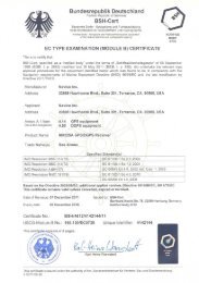
Instruction manual6 INTRODUCTIONThe <strong>RS82</strong> is a modular, dual station <strong>VHF</strong> radio and Class DDSC (Digital Selective Calling) radio-telephone system usinga fully-featured telephone-style handset to access and controlall functions. It supports the latest GMDSS requirements forINT16VOLUME 1 1SQUELCH 07LIFTCOVERVOLDISTRESSTEL CALLON/Cnon-SOLAS vessels from the International MaritimeOrganisation (IMO) and will enable you to make digitallyselected calls, which are quicker and simpler to make thantraditional voice calls using channel 16. Should a distress situationoccur, with the AHS82 you can quickly raise an alert,indicating your identity, your position and automaticallyestablish distress communication on the emergency voicechannel.VOLSPEAKER LAT/LONWX WATCHDIRCH SETThe transceiver “black box” is robustly constructed using apressure die-cast aluminium case for effective heat dissipation,ensuring maximum transmission performance even aftermany hours constant use.The operation of the AHS82 handset, which has a separateexternal loudspeaker, is designed to be simple and intuitive.Large buttons and a rubber-profiled handle-back ensure safeand comfortable handling, whilst the over-sized, backlit LCDand numeric keypad allow easy reading, even in difficultconditions.AHS82 handsetThe handset is tough and waterproof, designed to withstandthe rigours of the marine environment.7 MAIN FUNCTIONS7.1 General notesAlthough it has many advanced features, the AHS82 has beendesigned to be as simple and intuitive to operate as possible.The SHIFT key is used to access the secondary functions printedabove each key – press SHIFT, then press the appropriate key.These secondary functions are shown in this manual in brackets,e.g. (GROUP).NOTEShift mode will automatically time out after 2 seconds, unlessanother key is pressed. At any time, pressing ON/C will cancelthe current operation.The lowest occupied port is the master controller, any operationsinitiated on this handset will override all other stations.E0457243
RS81/<strong>RS82</strong> <strong>VHF</strong>7.2 Switching on/off & Second country modeTo turn the radio on (or off), press and hold the ON/C key. Onstart-up the display will show the handset software issue numberfor 2 seconds, then the station number and software issuenumber for the transceiver unit for 2 seconds.As default, the radio is tuned to the priority channel (normally16). If last used channel mode has been set (see section 8.3.3),the radio will switch on tuned to the previously used channel.The radio also stores volume and squelch settings automaticallyand will revert to these on start-up.In countries where it is permitted, the <strong>RS82</strong> can operate on asecondary set of channels, such as the USA channels.To select the secondary channel mode, press SHIFT followed byOK. The display will show the channel set selected for 2 seconds,before reverting to the default display.NOTEChannels available will depend on programming. Please enquirewith your national licensing authority for details of permittedchannel sets in your own country.7.3 Changing channelsTo select a channel, enter the channel number using the numerickeypad (Fig 7.1). If the channel is invalid, the display willshow “INVALID CHANNEL”, before reverting to the previouschannel.INT16VOLUME 05SQUELCH 03INT72VOLUME 05SQUELCH 03Fig 7.1 - Selecting a channelThe priority channel (normally 16) can be selected by pressing16, which will also set the radio to 25W (high) transmit power.44 E04572
Instruction manualThe pre-selected User channel can be directly selected by pressingthe USER key. The display will show “U” next to the channelnumber to indicate that it is the User channel (Fig 7.2).INTU 23VOLUME 05SQUELCH 03Fig 7.2 - User channel selectedThe default setting for the User channel is 16 (please refer tosection 8.3.1 for details on how to set the User channel).7.3.1 Channel setsIn addition to the standard international channels, the <strong>RS82</strong> canalso be programmed with regional auxiliary channels, such asthe Marina channels M and M2 in the UK, the USA Weatherchannels and the Fishing or Leisure channels in Scandinavia.To display the channel sets available, press SHIFT followed by1W (CH SET). Repeated pressing of the 1W key while still inShift mode will scroll through the available channel sets. Whenthe required channel set is displayed, enter the channel numberusing the numeric keypad – e.g. “2” for M2 (Fig 7.3).INTMAR I NAAAAAMAR I NAAAAAPR I VATE AAAFig 7.3 - Selecting auxiliary channel sets(sets must be available to be displayed)E0457245
RS81/<strong>RS82</strong> <strong>VHF</strong>The only exception to this is the selection of the UK Marinachannel “M”, which has no number associated with it.Selecting the Marina channel will set it automatically (Fig 7.4).INT2MAR I NAAAAAFig 7.4 - Selecting auxiliary channel numberNOTEIf no numeric keys are pressed within 2 seconds, the radio willrevert to the working channel (except for Marina channel “M”as noted above).7.4 Volume adjustmentTo adjust the volume, use the VOL ▲ and VOL ▼ keys toincrease or decrease the setting from 1 to 24 (loud). Pressingand holding either key will cycle through the settings.7.5 Squelch adjustmentTo enter squelch adjustment mode press SQ, then use the VOL ▲and VOL ▼ keys to increase or decrease the squelch from 0(open) to 10. Press and hold either key to scroll through thesettings.NOTE Squelch adjustment mode will automatically time out after 2seconds, unless another key is pressed. Squelch mode can alsobe cancelled by pressing ON/C.46 E04572
Instruction manual7.6 Dual Watch modeDual Watch mode allows the radio to scan between the selectedworking channel and the watch channel (the priority channel,usually 16).To enter Dual Watch, select the required working channel, thenpress SHIFT and 3 (DW). If Dual Watch is selected while thehandset is off the cradle, the display will show “PLACE BACKON CRADLE”. Dual Watch will automatically commence, ifthe handset is replaced within 10 seconds.The display now shows “D/W” – the large digits on the displaywill indicate the working channel, with the watch channelshown below in small digits (Fig 7.5).INT6DWD/WAAAAA 16BBBBBBBBBBFig 7.5 - Dual Watch modeIf the radio detects a signal on the Watch channel, it will lockonto this and the large digits will change to show the watchchannel.NOTENOTEAll other stations will also show the Dual Watch display.Normal <strong>VHF</strong> functions will not be available when in DualWatch mode. To exit Dual Watch press 16, or ON/C, or lift thehandset from the cradle.E0457247
RS81/<strong>RS82</strong> <strong>VHF</strong>7.7 Triple Watch or Tri-Watch modeTriple or Tri-Watch allows the radio to scan between the selectedworking channel, the User channel and the watch channel.Press & holdTo enter Tri-Watch, select the required working channel, pressSHIFT and then press and hold 3 (DW) for 2 seconds. If TripleWatch is selected while the handset is off cradle, the display willshow “PLACE BACK ON CRADLE”. Tri-Watch will automaticallycommence, if the handset is replaced within 10 seconds.The display will now show “T/W” – with the large digits onthe display indicating the working channel, and the User andwatch channels shown below in small digits (Fig 7.6).INT10T/WAAAAA 16USERBBBBB6Fig 7.6 - Tri-Watch modeIf the radio detects a signal on the User or Watch channels, itwill lock onto this and the large digits will change to show therelevant channel.NOTE Tri-Watch cannot be selected if the User channel is set to 16.NOTENOTEAll other stations will also show the Tri-Watch display.Normal <strong>VHF</strong> functions will not be available when in Tri-Watchmode.To exit Tri-Watch, press 16 or ON/C, or lift the handset from thecradle.48 E04572
Instruction manual7.8 All scan modeThe scan function cycles the <strong>RS82</strong> sequentially through eachenabled channel, pausing each time a signal is detected.Press SHIFT followed by 1 (SCAN ALL) to enter All scan mode. IfAll scan is selected while the handset is off the cradle, the displaywill show “PLACE BACK ON CRADLE”. All scan will becancelled if the handset is not returned to the cradle within 10seconds.When the radio detects a signal, the display will change toshow the relevant channel number (Fig 7.7).INT67SCANALLFig 7.7 - All scan modeShould the radio lock onto a busy channel, pressing OK willmanually continue the scan. All scan will otherwise automaticallyrestart when the channel becomes clear.NOTENOTEAll other stations will also show the All scan display.While in All scan mode, normal <strong>VHF</strong> functions are not available.To exit All scan, press 16 or ON/C, or lift the handset fromthe cradle.7.8.1 Dynamic All scan inhibitDuring All scan, if the radio repeatedly locks onto a busy channel,this channel can be excluded from scanning by pressingSHIFT then 1 (SCAN ALL) while locked onto it. The display willshow “CHANNEL INHIBITED” and the channel will nolonger be included in the scan cycle.The channel can be reinstated using Memory scan select(please refer to section 8.1.4).E0457249
RS81/<strong>RS82</strong> <strong>VHF</strong>7.9 Memory scan modeMemory scan allows scanning a pre-programmed set of channelsspecified by the user (see also sections 8.1.4 and 8.1.5).To enter Memory scan mode press SHIFT then 2 (SCAN M). IfMemory scan is selected while the handset is off the cradle, thedisplay will SHOW “PLACE BACK ON CRADLE”. Memoryscan will automatically commence, if the handset is replacedwithin 10 seconds.The display will show “SCAN M”. When the radio detects asignal, it will lock onto this and the large digits will change toshow the relevant channel (Fig 7.8).INT68SCANMFig 7.8 - Memory scan modeShould the radio lock onto a busy channel, pressing OK willmanually continue the scan. Memory scan will otherwise automaticallyrestart when the channel becomes clear.NOTENOTENOTEIf only one channel has been stored initiating Memory scanwill retune the <strong>RS82</strong> to this channel.All other stations will also show the Memory scan display.While in Memory scan mode, normal <strong>VHF</strong> functions are notavailable.To exit Memory scan, press 16, or ON/C, or lift the handsetfrom the cradle.7.9.1 Dynamic Memory scan deleteIf the radio repeatedly locks onto a busy channel when scanning,this channel can be removed from the Memory scan bypressing SHIFT then 2 (SCAN M) while locked on that channel.The display will show “CHANNEL DELETED” and the channelwill no longer be included in the scan cycle.50 E04572
Instruction manual7.10 Adjusting backlightingBoth the LCD display and keypad are backlit – to enter backlightingmode press SHIFT followed by CALL (DIMMER), thenuse the VOL ▲ and VOL ▼ keys to adjust the backlighting levelfrom “OFF” through level 1 (bright) to 5.Press OK or ON/C to exit the backlighting mode.NOTEBacklighting levels are set individually and will only affect theindividual station.7.11 Handset off cradleWhen a handset is lifted off its cradle, all other stations willdisplay “OCCUPIED” (Fig 7.9). This means that these stationsare locked out until the handset is returned to the cradle,unless it is an intercom call (see section 11.5).INT16STAT I ONAA2OCCUP I EDBBFig 7.9 - Station 2 handset is in useNOTEHowever, lifting the master handset will override all other stations,even if it is displaying “OCCUPIED”. All other stationswill be automatically locked out and display “OCCUPIED”instead.E0457251
RS81/<strong>RS82</strong> <strong>VHF</strong>8 MENU MODEMenu mode is used to adjust the various settings of the radio,such as channels inhibited from scan functions, MMSI numberprogramming and User channel selection.To enter Menu mode, press SHIFT followed by 9 (MENU).Use the VOL ▲ and VOL ▼ keys to scroll through the menuoptions below:• Scanning (section 8.1) – Options related to the variousscanning functions such as channel inhibit, memory scanselect and scan dwell time.• Numbers (section 8.2) – Entering of ID numbers such asMMSI, Group MMSI and ATIS numbers (if applicable incountry of use).• <strong>VHF</strong> Items (section 8.3) – Miscellaneous options such asselection of User channel, last used channel, interrupt intercom,speaker settings and SimNet management.To select an option, press OK. To return to normal radio operation,press ON/C.NOTEEntering Menu mode will inhibit the operation of the radio.Exit Menu mode before returning the handset to the cradle topermit normal operation.8.1 ScanningOnce the Scanning menu option has been selected (see introductionto section 8), use the VOL ▲ and VOL ▼ keys to scrollthrough the menu options below:• All scan inhibit (section 8.1.1)• All scan reset (section 8.1.2)• All scan show (section 8.1.3)• Memory scan select (section 8.1.4)• Memory scan clear (section 8.1.5)• Memory scan show (section 8.1.6)• Scan dwell time (section 8.1.7)To select an option, press OK. To return to the main menu,press ON/C.8.1.1 All scan inhibitIf the radio is repeatedly locking onto a busy channel whenscanning, this channel can be inhibited, i.e. excluded from thescan cycle.52 E04572
Instruction manualFrom the Scanning menu select “ALL SCAN INHIBIT” andpress OK. Enter the relevant channel number using the numerickeypad. The display will show the channel number and its currentstatus – “ALL SCAN” for enabled, or “ALL SCAN INHIB-ITED” for excluded channels (Fig 8.1). Use the OK key tochange the channel’s status.INT65ALL SCANAAINH IB ITEDBFig 8.1 - Selected channel inhibited from scanRepeat the above procedure to enable or inhibit further channels,or use the VOL ▲ and VOL ▼ keys to select another menuoption. To exit this menu level, press ON/C.8.1.2 All scan resetTo reset all inhibited channels select “ALL SCAN RESET” fromthe Scanning menu and press OK. The display will show“CHANNELS RESET” (Fig 8.2).CHANNELSSSRESETEDBBBFig 8.2 - All inhibited channels resetUse the VOL ▲ and VOL ▼ keys to select another option, orON/C to return to the upper menu level.8.1.3 All scan showThis function will display all inhibited channels. From theScanning menu select “ALL SCAN SHOW” and press OK. Thedisplay will change to “SHOWING CHANNELS” and displayall inhibited channels in sequence.Press the VOL ▲ and VOL ▼ keys to select a further option, orON/C to return to the main menu.8.1.4 Memory scan selectThis function selects the channels to be used in the Memoryscan cycle (see section 7.9).E0457253
RS81/<strong>RS82</strong> <strong>VHF</strong>From the Scanning menu choose “MEM SCAN SELECT” andpress OK. Enter the relevant channel number using the numerickeypad. The display will show the channel number and itsmemory status – “MEM SCAN” if it is not currently selectedfor memory scan, or “MEM SCAN ENABLED” if it is alreadyselected (Fig 8.3).INT65MEM SCANAAINT65MEM SCANAAENABLEDB BCHANNEL CURRENTLY NOT SELECTEDCHANNEL ALREADY SELECTEDFig 8.3 - Selecting channel for Memory scanUse the OK key, to change the channel’s status – i.e. if it is notselected, pressing OK will add it to the Memory scan cycle andvice versa.Repeat the above procedure to select or deselect further channels.When finished, press ON/C to return to the main menu, oruse the VOL ▲ and VOL ▼ keys to select another menu option.NOTENorth American users – Only one Weather channel can bestored in the memory scan; if another one is selected, it willoverride the existing channel. The Weather channel is notscanned as part of the memory scan sequence, it is in fact usedby the Weather Watch function (see section 11.1).8.1.5 Memory scan clearMemory scan clear will remove all previously selected channels.To clear all channels select “MEM SCAN CLEAR” fromthe Scanning menu, then press OK – the display will change toshow “CHANNELS CLEARED” (Fig 8.4).CHANNELSSSCLEAREDBBBFig 8.4 - Clearing all previously selected channelsPress the VOL ▲ and VOL ▼ keys to select another Scanningmenu option, or press ON/C to return to the main menu.54 E04572
Instruction manual8.1.6 Memory scan showThis function displays all channels selected for Memory scan.From the Scanning menu select “MEMORY SCAN SHOW” andpress OK. The display will change to “SHOWING CHANNELS”and display all enabled channels in sequence.Press the VOL ▼ or VOL ▲ key to select another Scanning menuoption, or ON/C to return to the main menu.8.1.7 Scan dwell timeThis function is used to select the amount of time the <strong>RS82</strong>remains on a channel, after it has locked onto it during a scanningfunction (All scan or Memory scan) and the signal is lost.From the Scanning menu (section 8.1) select “SCAN DWELLTIME XX” (where “XX” denotes the current dwell time in seconds),then press OK (Fig 8.5).SCAN DWELLT I ME 04Fig 8.5 - Scan dwell timeThe default time is “0”, meaning that the scan will continue assoon as the signal is lost. There are 11 levels from 0–10 seconds.Use the numeric keys to enter the scan dwell time and press OKto select – the display will show “DWELL TIME XX SECONDS”.Press the VOL ▲ or VOL ▼ key to select another Scanning menuoption, or ON/C to return to the main menu.8.2 NumbersThe Numbers menu is used for entering ID numbers such asMMSI, Group MMSI and ATIS (if applicable in country of use).Once the Numbers menu option has been selected (see introductionto section 8), the VOL ▲ and VOL ▼ keys to scrollthrough the menu options below:• Ship’s MMSI (section 8.2.1)• Group MMSI (section 8.2.2)• ATIS number (section 8.2.3)NOTEThe ATIS number option will only be shown if the radio isATIS enabled. This feature is only available for sets used in theBenelux and Rhine/Danube waterways.To return to the main menu, press ON/C.E0457255
RS81/<strong>RS82</strong> <strong>VHF</strong>8.2.1 Ship’s MMSIThis function will display the boat’s MMSI (Maritime MobileService Identity) number, provided it has already been entered,or allow the MMSI to be entered if the radio is being used forthe first time (cf. section 1.3).CAUTIONThe MMSI number can only be entered once and cannot beedited by the user. Should it become necessary to change theMMSI number (for example, if the radio is being moved toanother boat), the radio must be sent to an authorised <strong>Simrad</strong>service agent for reprogramming.From the Numbers menu (section 8.2) select “SHIPS MMSI” andpress OK – the display will show the MMSI number, unless thenumber has not been entered yet, in which case it will showdashes only (Fig 8.6). To enter the MMSI number, press OKagain. The display will show “ENTER MMSI” and the firstdash will start flashing to indicate that entry can begin.INT16SH I PS MMS Ii- - - - - - - - -Fig 8.6 - Entering the MMSI numberEnter the nine-digit MMSI number using the numeric keypadand press OK. The radio will then ask the MMSI number be reentered(“CONFIRM”). If the two numbers do not match, theprocedure must be repeated.Use the CALL and MSG keys to move the cursor to correctany errors. The cursor position is indicated by the flashingnumber. Enter a new number to overwrite an incorrect number.NOTEThe MMSI number will not be accepted, unless all nine digitshave been entered.Press ON/C to return to the main menu.8.2.2 Group MMSIFor boats that are part of a flotilla, racing/fishing fleet or othergroup, a Group ID MMSI (Maritime Mobile Services Identity)number can also be entered and used to contact other boats inthe same fleet (see also section 1.4).56 E04572
Instruction manualNOTEThe Group MMSI number may be allocated on a temporarybasis by the local administration, for this reason the numbercan be changed by the user.From the Numbers menu (section 8.2) select “GROUP MMSI”and press OK – the display will show the Group MMSI, unlessthe number has not been entered yet (in which case it will show“_ _ _”). To enter the Group MMSI number press OK again. Thedisplay will change to show “ENTER MMSI” and the first dashin the number will start flashing to indicate that entry can begin.The first digit of a Group MMSI number is always “0” and thisis pre-selected by the radio. Enter the remaining eight digitsusing the numeric keypad and press OK (Fig 8.7).INT16GROUP MMS II0436 1 ----Fig 8.7 - Entering a Group MMSI numberUse the CALL and MSG keys to correct any errors. Thecursor position is indicated by the flashing number. Enter anew number to overwrite an incorrect number.NOTEThe number will not be accepted unless all eight remainingdigits have been entered.Press ON/C to return to the main menu.NOTECAUTION8.2.3 ATIS numberThis section applies only to radios used in countries where theATIS system is in operation (i.e. Benelux and the Rhine/Danubewaterways). This option will only appear on ATIS-equippedradios. (Please refer to section 1.5 also.)The ATIS number can only be entered once and cannot be editedby the user. If it is necessary to change the ATIS number, theradio must be sent to an authorised <strong>Simrad</strong> service agent forreprogramming.From the Numbers menu (section 8.2) select “ATIS NO”; thedisplay will show the ATIS number, unless the number has notbeen entered yet (in which case it will show “_ _ _”).E0457257
RS81/<strong>RS82</strong> <strong>VHF</strong>To enter the ATIS number press OK again. The display will nowshow “ENTER ATIS” and the first dash in the number will startflashing to indicate that entry can begin.Enter the nine-digit ATIS number using the numeric keypadand press OK. The radio will then ask the number be re-entered(“CONFIRM”). If the two numbers do not match, the proceduremust be repeated.Use the CALL and MSG keys to move the cursor to correctany errors. The cursor position is indicated by the flashingnumber. Enter a new number to overwrite an incorrect number.NOTEThe ATIS number will not be accepted, unless all nine digitshave been entered - the prefix “9” is automatically inserted bythe radio.Press ON/C to return to the main menu.8.3 <strong>VHF</strong> ItemsThe <strong>VHF</strong> Items menu contains the settings for miscellaneousfunctions such as User channel, position view, speaker settings,as well as SimNet management and lighting modes.Once the <strong>VHF</strong> Items menu option has been selected (see introductionto section 8), use the VOL ▲ and VOL ▼ keys to scrollthrough the available menu options:• User channel (section 8.3.1)• Position view (section 8.3.2)• Last used channel (section 8.3.3)• Interrupt intercom (section 8.3.4)• Speaker settings (section 8.3.5)• SimNet management (section 8.3.6)• Lighting modes (section 8.3.7)To select an option press OK. To return to the main menu pressON/C.8.3.1 User channelThis is a user-programmable priority channel that is used in theTri-Watch function and can be selected by pressing the USERkey.From the <strong>VHF</strong> Items menu (section 8.3) select “USER CHAN-NEL” and press OK. Using the numeric keypad enter the requi-58 E04572
Instruction manualsite channel number and press OK. The display will show“SET USER CHANNEL” (Fig 8.8).INT10SET USERAACHANNELBBBFig 8.8 - Setting the User channelUse the VOL ▲ and VOL ▼ keys to select another option, orpress ON/C to return to the main menu.8.3.2 Position viewThis option allows the user to view the current GPS positionthat will be used if a distress call is made (Fig 8.9). The functionof this option depends on whether the position is receivedautomatically via NMEA, or has been entered manually.INTLATLON1689º 23. 000N102º 54. 120EFig 8.9 - Position displayFrom the <strong>VHF</strong> Items menu (section 8.3) select “POSITIONVIEW” and press OK. If GPS position information is beingreceived, the display will show “POSITION VIEW OFF”. Usethe OK key to toggle between “ON” and “OFF”.When this option is turned on, the bottom two lines of the displaywill show the current “LAT/LON” positions on all handsets.If the volume or squelch is being adjusted, the displaywill show the settings while the VOL ▲ / VOL ▼ keys are operated,before reverting to the position display.If no GPS position information is being received, the displaywill show “VIEW”. Pressing OK will show the position enteredmanually, or the last known GPS position. If no position hasbeen entered, the “LAT/LON” display will show “9 9 9” only.E0457259
RS81/<strong>RS82</strong> <strong>VHF</strong>Use the VOL ▲ and VOL ▼ keys to toggle between position andtime (UTC) displays.Press ON/C to exit, or use the VOL ▲ and VOL ▼ keys to chooseanother option.8.3.3 Last used channelNormally the <strong>RS82</strong> will power up on the pre-programmedstart-up channel (usually the priority channel). This functionenables the radio to power up on the last-used channel – thedefault setting is “OFF”.From the <strong>VHF</strong> Items menu (section 8.3) select “LAST USEDCHAN” and press OK – the current status will be displayed(“ON”/“OFF”). Use the OK key to toggle between the settings.Press the VOL ▲ and VOL ▼ key to select another option, orON/C to return to the main menu.8.3.4 Interrupt intercomThis function can be used to specify whether intercom functionsshould be interrupted when an incoming <strong>VHF</strong> transmissionis received – the default setting is “Y” (“Yes”).From the <strong>VHF</strong> Items menu (section 8.3) select “INTERRUPTINTERCOM” and press OK – the display will show the currentstatus (“Y” or “N”). Use the OK key to toggle between settings.Use the VOL ▲ and VOL ▼ keys to select another option, orON/C to return to the main menu.8.3.5 Speaker settingsThe speaker settings option is used to set individual defaultvolume levels for each station or intercom in the system.From the <strong>VHF</strong> Items menu (section 8.3) select “SPEAKER SET-TINGS” and press OK to enter the sub-menu. Use the VOL ▲and VOL ▼ keys to scroll through each speaker, displaying thedefault volume level for each one.NOTEOnly connected speakers will be shown.The first option in the sub-menu is “RESET TO DEFAULTS”(Fig 8.10, p. 61) – pressing OK will reset all speaker levels totheir default settings, the display will show “RESETTING LEV-ELS”. To set the required volume levels for each individualposition, use the VOL ▲ and VOL ▼ keys to select the requiredstation and press OK.The selected speaker will emit a continuous tone indicating thecurrent volume level. Press VOL ▲ and VOL ▼ to adjust the volumelevel as desired and press OK to confirm.60 E04572
Instruction manualINT16RESET TO000DEFAULTS00Fig 8.10 - Resetting speaker settings to defaultsPress the VOL ▲ and VOL ▼ keys to select another station andrepeat the above procedure, or ON/C to return to the uppermenu levels.NOTE8.3.6 SimNet managementThis option will only appear in the <strong>VHF</strong> Items menu, if theradio is operating on a SimNet bus.From the <strong>VHF</strong> Items menu select “SIMNET MANAGEMENT”and press OK (Fig 8.11).INT16SIMNETMANAGEMENTFig 8.11 - SimNet management pageUse the VOL ▲ and VOL ▼ keys to scroll through the availablemenus -• Data sources (section 8.3.6.1)• Lighting banks (section 8.3.6.2)• Device instance (section 8.3.6.3)• <strong>System</strong> instance (section 8.3.6.4)To select an option, press OK.To return to the <strong>VHF</strong> Items menu, press ON/C.E0457261
HDG-QPOS-QDIFCOGSOGROT239HS50RS81/<strong>RS82</strong> <strong>VHF</strong>8.3.6.1 Data sourcesThis function is used to select the data source for position, dateand time information, if the <strong>RS82</strong> is part of a SimNet systemwith more than one unit providing nav data (Fig 8.12). It willonly be shown if SimNet is present.CP44 ChartplotterHS50Satellite CompassFig 8.12 - Example of multiple data sources on one SimNet systemAs a default, the <strong>RS82</strong> will give priority to SimNet data overthat received via the NMEA input. This function enables you toselect the NMEA input as the priority data source.From the SimNet management menu select “DATA SOURCES”and press OK.Use the VOL ▲ and VOL ▼ keys to scroll through the followingoptions -<strong>Simrad</strong> Group – (Default) Accept the data source aspecifiedby the Group Owner. A Group Owner is a unit capable of dictatingwhich data source other SimNet units on the bus use.The Group Owner is usually a Chartplotter or similar unit.NMEA0183 – This option will select the NMEA0183 input asthe nav data source.SimNet units – The display will show the name and serialnumber of each SimNet unit detected on the network.Third Party units – The display will show the name and serialnumber of any third party units connected to the bus viaNMEA2000.NOTEApart from NMEA0183, a maximum of four other sourceswill be shown, and these will be the first four detected. Anyfurther sources apart from these will be ignored.Press OK to set the selected data source. The display will show“SOURCE SELECTED”, then exit to the SimNet managementmenu.NOTEIf the selected data source is lost, the radio will automaticallyselect another SimNet or NMEA source if available, otherwisethe display will show “SOURCE DATA LOST”.62 E04572
Instruction manual8.3.6.2 Lighting banksThis function allows individual RS80 stations to be assigned todifferent lighting banks across the SimNet bus. It enablesgroups of SimNet products to be set up as “zones”, whichshare the same backlight settings. This is useful on vesselswith, for example, an interior and an exterior steering position,where the ambient lighting (and therefore backlightingrequirement) is different (Fig 8.13).FLYBRIDGE (bank 1)WHEELHOUSE (bank 2)Fig 8.13 - Example of vessel with two lighting banksThus, on a flybridge cruiser all the equipment fitted on the flybridgecan be assigned to lighting bank 1 and the equipment inthe wheelhouse can be assigned to lighting bank 2.Adjusting the lighting on one unit in bank 1 will be duplicatedon all other products in the same bank, but will not affect anyunits in bank 2.From the SimNet management menu select “LIGHTINGBANKS” and press OK.Use the VOL ▲ and VOL ▼ keys to select the station you wantto assign to a particular lighting bank.Use the numeric keypad to enter the bank number (0–63).Press OK to confirm.Repeat the above sequence for each station fitted to the <strong>RS82</strong>.Press ON/C to exit to the SimNet management menu.NOTEAll IS12 instruments are set to “BANK 0” by default. It is notpossible to split IS12 displays into separate banks.E0457263
RS81/<strong>RS82</strong> <strong>VHF</strong>8.3.6.3 Device instanceThis option will normally only be used on very large, complicatedsystems, where there is more than one RS80 system onthe same SimNet bus. For example, on certain vessels it may benecessary to have more than one <strong>VHF</strong> radio fitted with differentchannel configurations (Fig 8.14).<strong>VHF</strong> nº 1<strong>VHF</strong> nº 2Fig 8.14 - Multiple RS80 <strong>VHF</strong>s on the same networkTo prevent conflict across the network, these can each beassigned a unique device number.NOTE“More than one RS80 system” refers to a complete systemradio, including the Rx/Tx transceiver, NOT to a single RS80with multiple stations – that is still classed as one radio.From the SimNet management menu select “DEVICEINSTANCE” and press OK.The default device instance number is “000”. Use the numerickeypad to enter the required device instance number and pressOK to confirm (Fig 8.15).SELECTNO. 000SELECTNO. 001Fig 8.15 - Entering a device numberThe display will show “SELECTED” and the entered devicenumber for 2 seconds, then exit to the SimNet managementmenu.64 E04572
Instruction manual8.3.6.4 <strong>System</strong> instanceA SimNet bus can have a maximum of 50 devices (or “nodes”)attached to it. If a large vessel has a requirement for more than50 nodes, then a multiple network system is required.The system instance allows the user to allocate a unique numberto each network, which allows the multiple networks tointercommunicate.NOTEIf your vessel is large enough that it is likely to require settingup multiple networks, it is strongly advised that you contact<strong>Simrad</strong> Technical Support to discuss your particular systemrequirements before proceeding further.From the SimNet management menu select “SYSTEMINSTANCE” and press OK.The default system instance number is “00”. Use the numerickeypad to enter the required system instance number and pressOK to confirm (Fig 8.16).SELECTNO. 00SELECTNO. 01Fig 8.16 - Entering a system instance numberThe display will show “SELECTED” and the entered systemnumber for 2 seconds, then exit to the SimNet managementmenu.E0457265
RS81/<strong>RS82</strong> <strong>VHF</strong>8.3.7 Lighting modesThis option is used to select how the backlighting is controlledon the <strong>RS82</strong>. Backlighting control can either be limited to theindividual station, to the whole RS80 system, or across theSimNet bus.From the <strong>VHF</strong> Items menu select “LIGHTING MODES” andpress OK.Use the VOL ▲ and VOL ▼ keys to scroll through the options(Fig 8.17) -Station<strong>Radio</strong>NetworkAll stations are independent.All stations will respond to a common level.All stations respond to the network level (forthe specified lighting bank).STATIONRADIONETWORKFig 8.17 - Lighting modesPress Ok to set the selected lighting mode. The display willshow the lighting mode selected, then exit to the <strong>VHF</strong> Itemsmenu.NOTEThis option is station specific. It will be necessary to duplicatethese settings to any other RS80 stations for them all to behavein the same manner.66 E04572
Instruction manual9 DSC FUNCTIONS9.1 GeneralThe <strong>RS82</strong> features full Class D DSC (Digital Selective Calling)functionality enabling the user to make digitally selected calls,which are quicker and simpler to make than traditional voicecalls using channel 16. Should a distress situation occur, aDistress Alert call can be initiated, indicating the vessel’s identity,position and automatically establish distress communicationon the emergency voice channel (normally channel 16).NOTEDSC functions will only be available, if the MMSI number hasbeen entered into the radio (see section 8.2.1).9.2 Making a call9.2.1 Individual routine callPress the CALL key to enter the individual routine call function.Enter the MMSI number of the station manually using thenumeric keypad, or use the VOL ▲ and VOL ▼ keys to scrollthrough the MMSI number directory (Fig 9.1). Press OK to confirmthe selected entry.INT06SEA M I STAAON CH 06 00Fig 9.1 - Selecting a number from the MMSI directoryNext enter the required reply channel using the numeric keypad,or use the VOL ▲ and VOL ▼ keys to scroll through thefour default reply channels (06, 08, 72 & 77). Press OK to confirm.NOTENOTEOnly simplex channels can be selected as working channels.If the MMSI number entered is for a coast station, the option toselect a working channel will not be available – this is specifiedby the coast station, and will normally be a duplex channel.The display will show “PRESS OK TO SEND” – press OK toinitiate the call, or ON/C to abort.E0457267
RS81/<strong>RS82</strong> <strong>VHF</strong>On initiation of the call, the display will show “AWAITINGACKNOWLEDG” (Fig 9.2). Once an acknowledgement isreceived, the radio will switch to the specified working channel.INT06AWA I T I NGAAACKNOWLEDGNOTEFig 9.2 - Call sent, awaiting acknowledgement from recipientIf an acknowledgement is not received, the radio will continueshowing “AWAITING ACKNOWLEDG” for 4.5 minutes beforetiming out and returning to normal operation.9.2.2 Public correspondence callFor vessels within range of a country operating the necessarynetwork, the <strong>RS82</strong> can be used to directly make and receivepublic correspondence calls from a land-based telephone systemvia a coast station. Press SHIFT, then ON/C to enter thepublic correspondence call function.Enter the telephone number manually using the numeric keypad(Fig 9.3), or use the VOL ▲ and VOL ▼ keys to scrollthrough the telephone number directory. Press OK to confirmthe selected entry.INT0644 1 606547677------NOTEFig 9.3 - Dialling a number manuallyCheck with your local network provider for usage instructions.68 E04572
Instruction manualThe next stage is to specify the coast station the call is to berouted through. Either manually enter the MMSI number of thecoast station using the numeric keypad, or use the VOL ▲ andVOL ▼ keys to scroll through the Coast Station MMSI directory(Fig 9.4). Press OK to confirm the selected entry.INT06COAST 1 AAAFig 9.4 - Selecting a coast station from the Coast Station directoryNOTEThe MMSI number entered must have a “00”-prefix (whichindicates a coast station), or it will not be accepted.The display will show “PRESS OK TO SEND” – press OK toinitiate the call, or ON/C to abort. On initiation of the call, thedisplay will show “ATTEMPTING TO CONNECT”. If the callcannot be connected for any reason, the display will show“CANNOT CONNECT”, then “PLS WAIT 15 MINUTES”before returning to the default display.If the call is connected, the display will show “CALL INPROGRESS” (Fig 9.5) – press the PTT key to talk and release tolisten.INT07CALL I N AAAPROGRESSBBNOTEFig 9.5 - Call has been connectedThe channel number displayed during the call is determinedby the coast station.Press ON/C to end the call, or wait for the other participant toreplace the receiver.E0457269
RS81/<strong>RS82</strong> <strong>VHF</strong>9.2.3 All Ships Safety callTo make an All Ships Safety call, lift the protective cover on thefront of the handset and press the SAFETY key. The display willshow “SAFETY ON CH 16” (Fig 9.6). Enter the required workingchannel using the numeric keypad, or use the VOL ▲ andVOL ▼ keys to scroll through the four default reply channels(06, 08, 72 & 77). Press OK to confirm.INT06SAFE T YAAAAON CH 16 00NOTEFig 9.6 - Making an All Ships Safety callOnly simplex channels can be selected as working channels.The display will show “PRESS OK TO SEND” – press OK toinitiate the call, or ON/C to abort.9.2.4 All Ships Urgency callTo make an All Ships Urgency call, lift the protective cover onthe front of the handset and press the URGENCY key. The displaywill show “URGENCY ON CH 16” (Fig 9.7).INT06URGEN CYAAAON CH 16 00NOTEFig 9.7 - Making an All Ships Urgency callAll Ships Urgency calls must use channel 16 for voice communication,the option to manually select a working channel isnot available.The display will show “PRESS OK TO SEND” – press OK toinitiate the call, or ON/C to abort.70 E04572
Instruction manual9.2.5 Group callPress the SHIFT key twice to enter the group call function – thedisplay will show the Group ID MMSI number stored in theradio (see also section 8.2.2).Enter the required working channel using the numeric keypad, oruse the VOL ▲ and VOL ▼ keys to scroll through the four defaultreply channels (06, 08, 72 & 77). Press OK to confirm (Fig 9.8).INT06026530 1 45ON CH 06BFig 9.8 - Making a group callNOTEOnly simplex channels can be selected as working channels.When the display changes to show “PRESS OK TO SEND” –press OK to initiate the call, or ON/C to abort.WARNING9.2.6 Distress Alert callThis call should only be made if the vessel is in a genuinedistress situation. It is an offence to send a Distress Alert callif the vessel or crew are not in danger.The distress button is located under the protective cover on thefront of the handset. Press the DISTRESS button to access theDistress Alert call function – the display will show “DISTRESSUNDEFINED” (Fig 9.9).INT--D I STRESSAAUNDEF I NED bFig 9.9 - Distress Alert menuE0457271
RS81/<strong>RS82</strong> <strong>VHF</strong>Use the VOL ▲ and VOL ▼ keys to scroll through the availableNature of Distress categories:• Undefined (default)• Abandoning• Piracy• MOB• Fire• Flooding• Collision• Grounding• Listing• Sinking• AdriftPress and hold the DISTRESS key to begin the 5-second countdown– the large digits will count down from 5 to 1 before initiatingthe Distress Alert, then the display will change to show“SENDING ALERT” (Fig 9.10).INT--SEND I NGAAAALER T BBBBBFig 9.10 - Sending a Distress AlertNOTEThe Distress Alert call can be aborted, if the DISTRESS key isreleased at any time before the 5-second countdown hasended. Press ON/C to return to normal radio operation.The Distress Alert call sent includes the vessel’s MMSI number,the nature of the distress as specified, the time the call was sentand the current position of the vessel (if the appropriate navigationalreceiver is connected to the radio, or a manual positionhas been entered; see section 11.3).The radio will switch to monitoring channel 16 and the displaywill show “AWAITING ACKNOWLEDG” until an acknowledgementis received. The radio will automatically repeat thealert approximately every four minutes, until either anacknowledgement is received, or ON/C is pressed (it is not recommendedthat the Distress Alert is cancelled manually by pressingON/C, unless you are requested to do so by the rescue authorities).72 E04572
Instruction manualWhen an acknowledgement is received from the Rescue CoordinationCentre, this will automatically cancel the DistressAlert transmission. The subsequent rescue co-ordination will beperformed using the voice channel (Ch 16).WARNINGIf a DSC distress alert is sent accidentally, cancel it immediatelyon the <strong>RS82</strong> by pressing the ON/C button to preventrepeats, then make the following announcement on Ch 16:“This is (name of vessel, call sign, MMSI)”“Cancel DSC Alert sent (date & time/UTC)”DO NOT simply cancel the DSC alert without verbally cancellingit as well, otherwise the rescue authorities will not beaware that this is a false alarm.9.3 Receiving a call9.3.1 Individual routine callIf an individual routine call is received, the radio will sound anincoming call alarm. The display will flash between displaying“CALL FROM”, the caller’s MMSI number and the specifiedworking channel (Fig 9.11).INT10CALL FROMA3453428599REPLY ONA0CH 0628599Fig 9.11 - Receiving incoming individual routine callIf the caller’s MMSI is stored in the MMSI directory (see section10.2), the display will show the name stored instead of theMMSI. Press OK to accept the call, or ON/C to reject it.If the call has been accepted, the display will show “SENDACKNOWLEDG”. Press OK to send a call acknowledgementand automatically switch to the specified working channel.E0457273
RS81/<strong>RS82</strong> <strong>VHF</strong>9.3.2 Public correspondence callA public correspondence call is a call made from a land-basedtelephone, which is routed via a coast station. This is onlyavailable in countries operating the necessary network.NOTEAt present, it is not possible to receive incoming calls on thepublic correspondence network – calls can only be made fromthe radio. This section is for reference purposes only.When a public correspondence call is received, the radio willsound an incoming call alarm. The display will flash between“TEL CALL FROM” and the caller’s telephone number. If thecaller’s number is stored in the telephone number directory(see section 10.3), then the display will show the name storedinstead of the telephone number (Fig 9.12).INT10TEL CALLA0FROM428599SIMRAD ONA08599Fig 9.12 - Receiving incoming public correspondence callPress OK to accept the call – the display will show “CALL INPROGRESS” – or ON/C to reject it.NOTEAs the telephone call is transmitted via a <strong>VHF</strong> channel specifiedby the coast station, it will still be necessary to press thePTT key to talk and release it to listen, as with a normal <strong>VHF</strong>call. The coast station will disconnect the call if the PTT is notpressed for 5 seconds at least every 45 seconds.To end the call, press the ON/C key, or wait until the other participantreplaces the receiver (an end call signal will be sent tothe radio). Replace the handset in the cradle.74 E04572
Instruction manual9.3.3 All Ships Safety callIf an All Ships Safety call is received, the radio will sound anincoming call alarm. The display will flash between “ALLSHIPS SAFETY” and the caller’s MMSI number. If the caller’sMMSI is stored in the MMSI directory (see section 10.2), thedisplay will show the stored name instead.Press OK to accept the call – the display will change to “REPLYON CH X” (where “X” is the specified working channel), orpress ON/C to reject the call. Press OK again to switch back tothe working channel.9.3.4 All Ships Urgency callIf an All Ships Urgency call is received, the radio will sound anincoming call alarm. The display will flash between displaying“ALL SHIPS URGENCY” and the caller’s MMSI number. If thecaller’s MMSI is stored in the MMSI directory, the display willshow the name stored instead (Fig 9.13).INT10ALL SHIPSSSURGENCY9 9FROMPRAY 0SEASPRAY 0Fig 9.13 - Incoming All Ships Urgency callPress OK to accept the call and automatically switch to channel16, or ON/C to reject it.NOTEAll Ships Urgency calls always use channel 16 as the workingchannel.E0457275
RS81/<strong>RS82</strong> <strong>VHF</strong>9.3.5 Group callIf the radio has a Group ID MMSI number (cf. section 8.2.2)and a group call is received, the radio will sound an incomingcall alarm. The display will flash between displaying “ROU-TINE GROUP CALL”, the caller’s MMSI number and the specifiedworking channel (Fig 9.14).INT06ROUT I NES SGROUP CALLFROMPRAY 03895623970Fig 9.14 - Incoming group callIf the caller’s MMSI number is stored in the MMSI directory(see section 10.2), the display will show the name storedinstead. Press OK to accept the call – the display will change to“REPLY ON CH X” (Fig 9.15), where “X” is the specified workingchannel – or ON/C to reject the call.INT06REPLY ONAACH 1 0BBBBBFig 9.15 - Working channel specified by incoming group callPress OK again to switch back to the working channel.76 E04572
Instruction manual9.3.6 Distress Alert callIf a Distress Alert call is received, the radio will sound anincoming call alarm. The display will flash between “DISTRESSALERT” and the caller’s MMSI number along with the natureof the Distress Alert.If the caller’s MMSI number is stored in the MMSI directory(see section 10.2), the display will show the name storedinstead of the MMSI number (Fig 9.16).INT06D I STRESS SALERT CALLS I NK I NG 03453428599Fig 9.16 - Incoming Distress Alert callPress OK to accept the call and automatically switch to channel16, or ON/C to reject the call. Full details of the Distress Alertmay be viewed in the call log (see section 9.4).NOTEDistress Alert calls always use channel 16 as the workingchannel.E0457277
RS81/<strong>RS82</strong> <strong>VHF</strong>9.3.7 Distress Alert acknowledgementIf an acknowledgement is received for a Distress Alert sent (normallyfrom a coast station or Rescue Co-ordination Centre), theradio will sound an incoming call alarm.The display will flash between “DISTRESS ACKNOWLEDG”and the MMSI number of the vessel in distress (or your MMSInumber, if the Distress Alert was sent by the <strong>RS82</strong> and the transmissionhas been cancelled).If the vessel’s MMSI number is stored in the MMSI directory(see section 10.2), the display will show the name storedinstead (Fig 9.17).INT06D I STRESS SACKNOWLEDGFORK I NG 0ROBERTA0 0NOTEFig 9.17 - Distress acknowledgement receivedThe MMSI number/name displayed will be that of the vesselin distress, not the station that has acknowledged the call.Press OK to accept the acknowledgement and automaticallyswitch to channel 16, or ON/C to ignore the call.NOTEDistress Alert calls always use channel 16 as the workingchannel.78 E04572
Instruction manual9.3.8 Distress Relay callThe Distress Relay facility enables an incoming Distress Alertcall to be forwarded via boats within receiving distance of thecall, thus increasing the potential range of the Distress Alertcall. If a Distress Relay call is received, the radio will sound anincoming call alarm.The display will flash between “DISTRESS RELAY” and thevessel’s MMSI number (Fig 9.18). If the vessel’s MMSI numberis stored in the MMSI directory (see section 10.2), the displaywill show the name stored instead.INT06D I STRESS SRELAY ALLFOR I NG 03453428599Fig 9.18 - Incoming distress relay callNOTEThe MMSI number/name displayed will be that of the vesselin distress, not the vessel that relayed the call.Press OK to accept the call and automatically switch to channel16, or ON/C to reject the call.E0457279
RS81/<strong>RS82</strong> <strong>VHF</strong>9.4 Viewing the call logThe call log records details of the last 20 DSC or telephone callsreceived, including date and time, the type of call and the callerID. There are two separate logs – one for standard calls, theother for distress calls.NOTEAll calls are logged, even those rejected by pressing ON/C.Press MSG to access the call log menu. If the call logs areempty the display will show “NO CALLS RECEIVED” beforereturning to the default display. Use the CALL and MSGkeys to switch between the standard call log (indicated by asmall “1” shown next to the large digits) and the distress calllog (indicated by a small “2” shown next to the large digits).Press the VOL ▲ and VOL ▼ keys to scroll through the logentries. The display will show the call type and the date/timethe call was received (Fig 9.19). The small digit shows the logtype (“1” - standard call log, or “2” - distress call log) and thelarge digits show the entry number – the first entry shown isthe most recent call.INTMSG1 03I ND I V I DUAL1 9- 1 2 1 452Fig 9.19 - Viewing call log entryNOTEThe date and time displayed uses the date/time data receivedfrom the navigational receiver interfaced with the radio, notfrom the incoming message. If a navigational receiver was notconnected to the radio at the time the message is received, thedate and time will not be displayed.Press OK to view the details of the selected call – the displaywill show the caller’s number (or the name if the number isstored in the directory).Press VOL ▲ and VOL ▼ to display any relevant additionalinformation, for example, the nature of distress and the positionof the vessel in distress if viewing the distress call log (Fig9.20, p. 81).80 E04572
Instruction manualINTMSG207D I ST ALERT1 4- 1 0 0937S I NK I NG 03453428599LA 56-52NLO 009-50EFig 9.20 - Displaying additional call informationPress ON/C to return to the log entries menu. Press ON/C againto exit the call log menu.9.5 Position over 4 hours oldNormally current position data is supplied automatically to theradio via an interfaced navigational receiver, or by manuallyentering a position.If the last recorded position is over 4 hours old, the display willSHOW “POSITION 4 HOURS OLD”. Press OK to confirm andmanually enter a position (refer to section 11.3), or press ON/Cto ignore the message.NOTEThis display will be shown 30 minutes after switch on, if thereis no NMEA position data being received, or the position hasnot been manually entered.E0457281
RS81/<strong>RS82</strong> <strong>VHF</strong>10 THE DIRECTORYThe directory function allows frequently used boat MMSI,Coast Station MMSI and telephone numbers to be stored in theradio. To enter the directory, press SHIFT then MSG (DIR).10.1 Switching between the directoriesThe large digits will show the current entry number and thesmaller digit to the left will show the currently selected directory:1. Boat MMSI directory2. Telephone number directory (used in public correspondenceonly)3. Coast Station MMSI directory (used in public correspondenceonly)Use the CALL and MSG keys to switch between directories.10.2 Viewing the directorySelect the appropriate directory using the CALL and MSGkeys. Use the VOL ▲ and VOL ▼ keys to scroll through thedirectory entries (Fig 10.1).INTDIR10 1SEASPRAY 0475394270INTDIR102ROBERTAY 09463872 1 5Fig 10.1 - Scrolling through the directory entries82 E04572
Instruction manual10.3 Entering a numberPress OK to begin entering a new number – the large digits willshow the entry number in the directory (“1” for the first entry).Enter the name first; use the VOL ▲ and VOL ▼ keys to scrollthrough the alphabetical characters and the numeric keypad toenter any numbers (Fig 10.2).INTDIR1 0 1SEASP---------------Fig 10.2 - Entering a new name into the directoryPress MSG to move the cursor forward, or CALL to moveback and correct any errors (the cursor position is indicated bythe flashing character, enter a new character to overwrite).Press OK to confirm the entry and move on to the MMSI entry.Use the numeric keypad to enter the number (Fig 10.3). Pressthe CALL and MSG keys to correct any errors. The cursorposition is indicated by the flashing number; enter a new numberto overwrite an incorrect number. Press OK to confirm andstore the entry in the directory.INTDIR1 0 1SEASPRAY 047539-----Fig 10.3 - Entering the MMSI numberPress ON/C at any time to abort to the default display.NOTEWhen using the Boat or Coast Station directories the entry willnot be accepted, unless all nine digits of the MMSI have beenentered.E0457283
RS81/<strong>RS82</strong> <strong>VHF</strong>10.4 Editing a numberSelect the directory entry to be edited and press OK. Use theVOL ▲ and VOL ▼ keys to highlight either the name or thenumber for editing – the selected field will flash. Press OKagain to begin editing the selected field.Use the CALL and MSG keys to move the cursor – the cursorposition is indicated by the flashing character. Enter a newcharacter to overwrite, use the numeric keypad to enter a number,or use VOL ▲ and VOL ▼ to scroll through the alphabeticalcharacters (Fig 10.4).INTDIR10 1SEASPRAY 0475394270Selected fieldwill flashINTDIR10 1SEASP-----475394270Fig 10.4 - Editing an existing directory entryPress OK to confirm and store the edited entry, or ON/C toabort entry.84 E04572
Instruction manual11 MISCELLANEOUS FUNCTIONS11.1 Selecting Weather WatchThe Weather Watch function enables the radio to monitor a singleweather channel specified in the memory scan select function(section 8.1.4). A transmission on a Weather channel is precededby a tone – if this is detected by the radio, it will trigger an alertallowing the user to switch to the Weather channel.To enable Weather Watch, press SHIFT followed by the USER(WX WATCH) key. The “WX” legend will be shown in the topleft-hand corner of the display and the selected weather channelwill be shown on the bottom line of the display (Fig 11.1).WX12WEATHERAAAWATCHBBBW4NOTENOTEFig 11.1 - Selecting Weather Watch modeIf a Weather channel has not been specified, the display willshow “NO WX CHAN SELECTED” and Weather Watch willnot be enabled (please refer to section 8.1.4 for instructions onhow to select a Weather channel).If the Weather Watch function is not available (e.g. if noWeather channels are programmed into the radio), the displaywill show “WX NOT ENABLED”.To cancel Weather Watch, press SHIFT then USER (WX WATCH).11.1.1 Weather Watch alertIf a Weather Watch alert tone is detected by the radio on thespecified Weather channel, the radio will sound a 10-secondalarm and the display will show “WEATHER ALERT”.Press OK to cancel the alarm and switch to the Weather channel,or ON/C to cancel the alarm and ignore the weather alert.NOTEBecause the Weather channels transmit a continuous carriersignal, it is not possible for the <strong>RS82</strong> to detect when the transmissionhas ended.Press ON/C to return to the working channel once the transmissionhas ended.E0457285
RS81/<strong>RS82</strong> <strong>VHF</strong>11.2 Security mode (voice scrambler)For additional security, a voice scrambler function is availableas an optional accessory. The scrambler uses frequency inversionto encrypt the transmission and will allow secure transmissionbetween compatible radios.To enable security mode press SHIFT followed by 0 (SCRM). Thedisplay will show “SEC”, indicating that security mode is on.To exit security mode, press SHIFT followed by 0 (SCRM) again,or ON/C.The security mode will be cancelled if the <strong>RS82</strong> is placed eitherinto another mode that requires the use of the PTT key (e.g.intercom), or if a DSC call is made/received.11.3 Losing SimNet dataIf the selected SimNet nav data source is lost for any reason,after one minute an alarm will sound to all station speakers,and the display will show “SOURCE DATA LOST” (Fig 11.2).INT16SOURCEDATA LOSTFig 11.2 - SimNet nav data source lostThe alarm will also be sent across the SimNet bus, where itmay be repeated by other equipment that is able to do so.Press OK or ON/C to cancel the alarm and return to the previousdisplay. The alarm can also be cancelled by other equipmenton the bus that is repeating the alarm.If nav data is also being received via the NMEA0183 input, the<strong>RS82</strong> will automatically switch to this source after the loss ofSimNet data.86 E04572
Instruction manual11.4 Losing NMEA dataIf the NMEA0183 nav data source is lost (and no SimNet navdata is being received), an alarm will sound to all stationspeakers after one minute and the display will show “NMEALOST” (Fig 11.3).INT16NMEA LOST--Fig 11.3 - NMEA0183 nav data source lostNOTEThe alarm for the loss of NMEA0183 data is not sent across theSimNet bus.Press OK or ON/C to cancel the alarm and return to the previousdisplay.11.5 Editing Latitude, Longitude and UTCNormally, position and time data should be supplied to the<strong>RS82</strong> via a GPS or other navigational device connected to theradio. However, if this is not possible, the position and timecan be entered manually.Press SHIFT then 8 (LAT/LON). The display will show “ENTERLAT”. Enter the Latitude using the numeric keypad (Fig 11.4).Use the CALL and MSG keys to move the cursor to correctany errors. The cursor position is indicated by the flashingnumber. Enter a new number to overwrite an incorrect number.INT12ENTER LA T ALA 52-B---Fig 11.4 - Manually entering the positionE0457287
RS81/<strong>RS82</strong> <strong>VHF</strong>The final digit specifies whether the Latitude is north or southof the Equator – use the VOL ▲ and VOL ▼ keys to togglebetween “N” and “S”. Press OK to confirm and move on toentering the Longitude (the display will show “ENTER LON”),or press ON/C to abort entry.Enter the Longitude using the numeric keypad. Use the CALLand MSG keys to move the cursor to correct any errors. Thecursor position is indicated by the flashing number. Enter a newnumber to overwrite an incorrect number.The final digit specifies whether the Longitude is west or eastof the Meridian – the VOL ▲ and VOL ▼ keys to toggle between“W” and “E”.Press OK to confirm and move on to entering the time (the displaywill show “ENTER UTC”), or press ON/C to abort entry.Enter the UTC time (formerly known as GMT) in 24hr-formatusing the numeric keypad (Fig 11.5).INT12ENTER U T CAUTC 19B----Fig 11.5 - Manually entering time (UTC)Use the CALL and MSG keys to move the cursor to correctany errors. The cursor position is indicated by the flashingnumber. Enter a new number to overwrite an incorrect number.Press OK to confirm all settings, or ON/C to abort entry.WARNINGThis data is only stored temporarily and will be lost when theradio is switched off. Since the accuracy of this information isvital in the event of a Distress Alert transmission being necessary,we strongly recommend that a GPS or other navigationaldevice is permanently interfaced with the radio. Thisdata will then be automatically supplied and updated withoutthe need for user intervention.88 E04572
Instruction manual11.6 Toggling between Lat/Long and UTC viewsIf the Position View option (see section 8.3.2) is turned on, thecurrent position will be displayed on the bottom two lines ofthe display.The UTC time can be displayed instead by pressing SHIFT then8 (LAT/LON) key for 2 seconds (Fig 11.6).Repeat the above key sequence to toggle between the positionand time displays.UTC 19B26-Fig 11.6 - Displaying UTC time11.7 IntercomIf the system comprises more than one station, or includesintercom speakers, it is possible to make an intercom call to aselected position from a handset.11.7.1 Making an intercom callPress SHIFT then 6 (INTERCOM) to enter intercom mode. Thedisplay will show “INTERCOM STN X – STN Y”, where “X” isthe ID of the current station being used and “Y” is the first ofthe other stations in the system (Fig 11.7).INT12I N T ERCOMAASTN 1 -STN2 BFig 11.7 - Making an intercom call to Station 2 from Station 1Press the VOL ▲ and VOL ▼ keys to scroll through the availablestation/intercom that can be called from the station:“Stn 1–Stn 2” Intercom call to Station 2“Int Spkr 1” Intercom call to Intercom speaker 1Press the PTT key or OK to activate the intercom, or press ON/Cto cancel. Once the call has been initiated, further presses of theON/C key will re-sound the call alarm. Pressing the PTT keywill open the audio path to the called station.E0457289
RS81/<strong>RS82</strong> <strong>VHF</strong>NOTE The call will be terminated, if it is not accepted within 15seconds.When calling an intercom speaker, use the VOL ▲ and VOL ▼keys while the PTT key is held to adjust the intercom speakervolume. This option is not available when calling another stationor making an all speaker / PA call – the current volumesettings for each position will be used.To end the intercom call, press ON/C or return the handset toits cradle.NOTENOTEWhile making an intercom call, all other stations will display“STATION X OCCUPIED”.If the interrupt intercom option (section 8.3.4) is disabled and a<strong>VHF</strong> transmission is being received, the display will show“SIGNAL PRESENT” until the transmission has ended. If intercominterruption is enabled, the intercom call will be interruptedif a <strong>VHF</strong> transmission is received.11.7.2 Receiving an intercom callIf an intercom call is received from another station, the displaywill show “INTERCOM FROM STN Y”, where “Y” is the ID ofthe station making the intercom call (Fig 11.8). To end an intercomcall, press ON/C or return the handset to its cradle.INT12I N T ERCOMAAFROM STN 22Fig 11.8 - Receiving an intercom call from Station 211.8 Station speaker muteFor complete silence at an operating position, the stationspeaker (including the handset speaker) may be muted. Tomute the speaker, press SHIFT followed by 7 (SPEAKER) on thespecific handset that is used with the speaker.To disable mute, press SHIFT followed by 7 (SPEAKER) again,use the VOL ▲ and VOL ▼ keys, or lift the handset from the cradle.If the system is powered down, the volume settings will berestored the next time the system is turned on.90 E04572
Instruction manualNOTE11.9 iDSCThis will only affect the speaker that is used with this specifichandset, e.g. handset 1 will only mute the speaker connectedto the Station 1 terminals. To mute any other speakers on thesystem it will be necessary to go to the relevant handset andselect mute.The <strong>RS82</strong> can be integrated with one of <strong>Simrad</strong>’s navigationaldisplays (the xx33, xx42 and xx52 series) enabling details ofany incoming DSC calls to be displayed on the unit. Pleaserefer to the instruction manual of the relevant unit for moredetails. (Section 12.1 provides interfacing details.)E0457291
PART IVINSTALLATION
Instruction manual12 INSTALLATION12.1 Physical installationThe RS81/<strong>RS82</strong> is a modular radio system that is very simpleto install. However, the performance of the radios is directlyaffected by the quality of the installation. Please read theseinstructions carefully before attempting installation. If in anydoubt, consult a qualified marine electronics engineer.12.1.1 Transceiver installationThe RS80B transceiver unit should be installed in a concealedlocation such as in a locker or behind the switch panel.WARNINGThe transceiver unit is not waterproof, it must therefore notbe installed in any location where it is likely to be exposed toexcess moisture (e.g. a wet locker or an outside locker).The fins on the top of the transceiver act as a heatsink to dissipateheat generated by the set when in use, which maintainsthe high efficiency of the radio. The free circulation of air isessential – if mounting the transceiver in an enclosed space,ensure that the space is well ventilated.The transceiver requires a flat surface with an area of at least170 x 245mm (6.8 x 9.8in) for mounting. Allow sufficient spacebeneath the unit for cable entry – at least 50mm (2.0in) is recommended.The surface should be rigid and sturdy enough tobe able to support the weight of the unit, taking into accountthe shock loads likely to be encountered when the vessel isunderway in heavy seas.Fix the transceiver unit to the surface using the four self-tappingscrews supplied. The four fixing points are at the cornersof the transceiver unit – the bottom two are underneath the terminalcover (Fig 12.1).Fig 12.1 - Transceiver box mountingE0457295
RS81/<strong>RS82</strong> <strong>VHF</strong>12.1.2 Handset installationThe handset should be sited so that engine noise and vibration,or other background noise does not make it difficult for theoperator to hear. As microphones and loudspeakers containpowerful magnets, the handset and speakers should not beinstalled within 1m (3ft 3in) of any compasses, whether magneticor electronic.The handset is connected to a 5m (16.5ft) extension cable, thereforethe handset should be fitted within reach of the transceiverbox (for longer runs 20m extension cables are also available asseparate accessories; please refer to section 13.8).The handset cradle should be mounted on a flat surface withenough space to allow the bulkhead socket for the extensioncable to be fitted alongside. Space should also be allowed forthe accompanying loudspeaker to be fitted nearby.NOTEThe handset and bulkhead socket are waterproof. However, ifthe handset is to be fitted in an exposed location (e.g. on theflybridge of a power boat), it is recommended that the handset,and especially the bulkhead socket, are fitted to an angled orvertical surface to prevent standing water lying on the handsetface or inside the bulkhead socket, which could corrode thepins.Fit the supplied template for the handset cradle to the desiredmounting location. Drill four 3.2mm (0.125in) pilot holes in theindicated positions. If drilling into GRP, it is recommended thatthe holes are also countersunk, to prevent the gelcoat splittingwhen the self-tapping screws are inserted.Fit the supplied template to the desired mounting location forthe bulkhead socket. Drill a 23.5mm (0.94in) hole and four2.4mm (0.1in) pilot holes. Again, the pilot holes should becountersunk if drilling into GRP. Fit the bulkhead socket andrun the cable to the transceiver box position.NOTEIt is recommended that the cable is routed away from any othercables carrying high current (e.g. mains power cables), orpulsed signals (e.g. transducer cables) to avoid possible interference.If the handset is being removed, the waterproof cover shouldalways be fitted to the bulkhead socket to protect the pins frompossible corrosion.96 E04572
Instruction manual12.1.3 Station speaker installationThe loudspeaker should be installed near the handset and canbe flush-mounted or surface mounted with the supplied pattress.Flush mountingSurface mountingAttach the self-adhesive gasket to the back of the loudspeaker.Remove the four detachable corners of the speaker which concealthe mounting holes. Apply the supplied cutting templateto the mounting position. Carefully cut out the aperturerequired for the speaker back and use the short self-tappingscrews provided. Refit the corners to conceal the screw fixings.Drill a 5mm (0.2in) hole for the speaker cable. Attach the selfadhesivegasket to the back of the loudspeaker. Remove thefour detachable corners which conceal the mounting holes. Fitthe pattress to the back of the speaker and use the long self-tappingscrews provided to fix the speaker and the pattress blockto the bulkhead. Refit the corners to conceal the screw fixings.12.2 Electronic installationElectronic installation is straightforward – all peripherals connectto the transceiver unit (“black box”) using the clearlylabelled plug-in terminals (Fig 12.2).NOTESTANDARD CONNECTIONSFig 12.2 - Transceiver terminal connectionsThe diagram shows the terminal bay with the standard connectionsand the SimNet connectors (see section 12.2.5).If it is necessary to shorten any of the cables, ensure the endsare re-tinned for the best quality connection.The transceiver unit is fitted with a 10Amp “blade”-type fuse.It is recommended that the radio is connected to a 10Ampfused switch or breaker on the boat’s switch panel.Connect the supplied power cable to the terminals markedPWR + and - as follows:TerminalNumber12WireColourRedBlackE0457297
SIMRADVOLSPKRSHIFTMENUSIMRAD AHS81OKON/CDIMMERSQLINTUSERWX WATCH1W D/W 16SCAN ALL SCAN MSIMRADVOLSPKRSHIFTMENUSIMRAD AHS81OKON/CDIMMERSQLINTUSERWX WATCH1W D/W 16SCAN ALL SCAN MRS81/<strong>RS82</strong> <strong>VHF</strong>12.2.1 HandsetA single cable links the control panel to the transceiver unit.The standard model can support up to two control stations (foravailable options see introductory section 1.1).One fixed station is supplied with the radio – additional stationsare supplied as separate accessories. The control stationscan be either an AHS81 handset, or an AHS82 handset which issupplied with a separate loudspeaker.Connect the main control station to the “Station 1” terminals onthe transceiver unit as shown (Fig 12.3).TerminalNumber12345678WireColourBrownGreenRedWhiteBlueYellowOrangeBlackFig 12.3 - Control panel terminal connectionsAn additional control station should be wired in the samemanner and connected to “Station 2”(Fig 12.4).Station 1Station 2Fig 12.4 - Example of a typical dual-station installation98 E04572
Instruction manual12.2.2 LoudspeakersThe <strong>RS82</strong> can be fitted with a <strong>Simrad</strong> LS80 station speaker orthird party station speakers with an impedance of 4Ω.Connect the station speaker to terminals 7 and 8 of the terminalstrip (Fig 12.5).TerminalNumber78WireColourOrangeBlackFig 12.5 – Station loudspeaker terminal connections12.2.3 NMEA0183 inputThe inbuilt NMEA0183 processor allows navigational positioninformation to be received from a GPS or Chartplotter. Theboat’s position is automatically transmitted when a DistressAlert is initiated. Note that this is only applicable in a system withan <strong>RS82</strong> handset.NMEA input must be of the 0183 format, versions 2.0–3.0, outputtingsentences GLL, RMC and ZDA at a Baud rate of 4800.The “NMEA Out” connections from the GPS/Plotter should beconnected to the “NMEA In” terminals as shown (Fig 12.6):TerminalNumber12WireReferenceCommon In -Data In +Fig 12.6 - NMEA input terminal connectionsE0457299
RS81/<strong>RS82</strong> <strong>VHF</strong>12.2.4 iDSC outputThe RS81/82 is designed to integrate with other <strong>Simrad</strong> equipment,which enables DSC call information to be displayed onthe 33, 42 and 52 series Chartplotters.Connect the iDSC input terminals of the chartplotter to the terminalsmarked “iDSC” as shown (Fig 12.7):TerminalNumber34WireReferenceiDSC -iDSC +Fig 12.7 - iDSC output terminal connections12.2.5 SimNet connectorsThe two circular ports in the centre of the panel serve as connectorsfor SimNet cables (Fig 12.8).Fig 12.8 - SimNet connectorsSimNetconnectors100 E04572
Instruction manual12.2.6 SummarySummary of the RS81/82 connections –STANDARD CONNECTIONSStation 1Station 2NMEA/iDSCPWRTerminalNumber12345678WireColourBrownGreenRedWhiteBlueYellowOrangeBlackTerminalNumber12345678WireColourBrownGreenRedWhiteBlueYellowOrangeBlackTerminalNumber1234WireReferenceCommon In -Data In +iDSC -iDSC +TerminalNumber+-WireReferenceRed (12v in)Black (0v)12.2.7 Cable strain reliefOnce all the cables have been run to the appropriate peripheralsand connected to the transceiver unit they should besecured to ensure that they are not snagged or exposed toexcess strain.Screw the strain relief tab to the cable exit port on the transceiverunit using the screws supplied and secure the cables tothe tab using the wraps as shown (Fig 12.9):Fig 12.9 - Cable strain reliefReplace the terminal cover and secure by tightening the retainingscrew.E04572101
RS81/<strong>RS82</strong> <strong>VHF</strong>12.3 Antenna installationThe most important factor in the performance of the radio willbe the quality and positioning of the antenna. Most recordedproblems with <strong>VHF</strong> radios are related to poor antenna siting,faulty cabling, poor quality cable joints and low voltage supply.Even a <strong>VHF</strong> as technically advanced as the RS81/<strong>RS82</strong> cannotcompensate for these factors. Therefore, if replacing an existing<strong>VHF</strong> installation, it is important that the antenna is thoroughlychecked for any faults or damage before use.As the range of <strong>VHF</strong> signals are governed by line of sight (seesection 13.3), the antenna should be placed as high as possible,while remaining clear of any metallic objects that could influenceits resonance.The most popular antennae for marine use are 1m (3ft 3in)long. On sailboats these are usually mounted on the masthead,where the length of the antenna keeps it clear from the navigationlights and windvanes, for example. This type of antennacan also be mounted on the cockpit roof or powerboat garages.Longer whip antennae are recommended for larger boats –these radiate the same total power as smaller antennae, butconcentrate it into a narrower beam, which is advantageous ona tall mast at extreme range, where concentrating the availablepower into a narrow horizontal beam becomes more important.However, if the antenna is not vertical when transmitting, thebeam will be angled either too high or too low (see the effect ofheel on range, Fig 12.10).Fig 12.10 - Effect of heel on range of longer whip antennaHere the wider beam of the shorter marine antenna will bemore universally effective, although the signal will be weaker(Fig 12.11, p. 103).Therefore vessels with a large heel angle (small sailboats)would be better choosing a short masthead antenna. Your localagent should be able to provide specific advice on antennachoice for the vessel it is to be fitted to.102 E04572
Instruction manualFig 12.11 - Effect of heel on range of 1m marine antennaWARNINGThe antenna coaxial cable and any connectors used must berated at 50Ω. Under no circumstances should standard domesticTV cable and connectors be used. Incorrectly rated cablingand connectors could result in power not reaching the antenna,but power could also be reflected back into the radio,damaging it in the process.The quality of connections and integrity of the cable (withoutbreaks in the sheathing) will directly affect the performance ofthe radio. Poor soldering or corrosion of the terminals canimpair performance. We recommend that screw or crimp terminaltype connectors are not used for any through-deck fittings –a good quality waterproof solder terminal connector will be lesssusceptible to poor connection due to corrosion of the contacts.To ensure the best performance of the radio, the antenna cableshould be routed where it is least likely to interfere with, orreceive interference from, other electronic equipment, such asechosounder transducer cables and high-current carryingcables.The antenna cable should terminate in a standard marinePL259 plug fitting. Connect the antenna plug to the socket onthe top of the transceiver unit and screw the retaining collardown (Fig 12.12).Fig 12.12 - <strong>VHF</strong> antenna connectionNOTETo avoid possible water damage to the radio, it is recommendedthat the antenna cable is looped to provide a drip path.E04572103
RS81/<strong>RS82</strong> <strong>VHF</strong>12.4 Electrical interference suppressionInterference generated by the alternator of the engine mayoccasionally cause problems. The RS81/<strong>RS82</strong> has beendesigned to minimise the effects of outside interference.However, precautions should still be taken: route the powersupply and antenna cables away from the engine compartment.The cable run should not be using the same trunking asother cables carrying high current. The antenna cable shouldalso be kept separate from the radio’s power cable.Engines with spark ignition – as well as some refrigerators –should be fitted with suppressors. Your local agent should beable to give advice on this, and supply suppression kits wherenecessary.104 E04572
Instruction manual13 FURTHER INFORMATION13.1 Operating proceduresThe following operating procedure summary has been proposedby the UK Maritime and Coastguard Agency. It is notexhaustive and should not be regarded as a replacement forinformation provided by the proper two-day <strong>VHF</strong>/DSC trainingcourse required for all <strong>VHF</strong> licence holders.13.1.1 Sending a Distress Alert1. Send a Distress Alert call (cf. section 9.3.6).2. Wait approximately 15 seconds for a DSC acknowledgementfrom the Coastguard or a ship station.3. On receipt of a DSC acknowledgement, or after about 15 seconds,transmit the following Distress Alert call on channel 16:“Mayday, Mayday, Mayday”“This is (name of vessel repeated three times)”“Mayday (MMSI number and name of vessel or call sign,spoken once, Position – Nature of distress - No of people)”“I require immediate assistance”“Over.”If the vessel is not in “grave and imminent danger”, an AllShips Urgency call followed by a spoken “Pan Pan” call or aroutine call to the nearest coastguard station may be moreappropriate.WARNINGIt is a prosecutable offence to initiate a Distress Alert call forany other reason than that the vessel and/or crew is in imminentdanger.13.1.2 Acknowledging and relaying a DistressAlert callWhen a DSC Distress Alert is received, an audible alarm willsound. Immediately cease any transmission that may interferewith distress traffic and continue a watch on channel 16.If there is no DSC acknowledgement from a coast station orship, after a short interval acknowledge by voice on channel 16:“Mayday (MMSI of vessel in distress, repeated three times)”“This is (name of own vessel, repeated three times)”“Received Mayday (state the assistance you can give)”“Over.”A similar response should be given to a distress relay, using thewords “Mayday Relay” instead of “Mayday”.E04572105
RS81/<strong>RS82</strong> <strong>VHF</strong>13.1.3 Cancelling a Distress AlertIf a DSC Distress Alert is sent accidentally, cancel it immediatelyon the RS81/<strong>RS82</strong> by pressing the ON/C button to preventrepeats, then make the following announcement on channel 16:“This is (name of vessel or call sign, MMSI)”“Cancel DSC Alert sent (date & time UTC)”“Over.”Do not simply cancel the DSC alert without verbally cancellingit as well, otherwise the rescue authorities will not be awarethat this is a false alarm.13.1.4 Alerting all vessels within rangeIf the vessel is outside of coast radio range and needs to issue asafety warning to all vessels within radio range, transmit an AllShips Safety call by DSC. After about 15 seconds transmit onchannel 16 the safety call and message as follows -“Securité, Securité, Securit锓All stations (or called station)” – repeat three times“This is (MMSI and name or call sign of own vessel)” –repeat text of safety message.“Over.”13.1.5 Calling a coast radio stationEnter the MMSI number of the station into the <strong>RS82</strong>, eithermanually or from the directory. When the call is acknowledged,the working channel for voice communication will be indicatedand the <strong>RS82</strong> will automatically switch to that channel. Make avoice call as normal.13.1.6 Making an intership callEnter the vessel’s MMSI into the <strong>RS82</strong>, either manually or fromthe directory. Before sending the call, enter the intership channelto be used for subsequent communication. When the alarmsounds on the called vessel, its operator should acknowledgeby DSC, then respond by voice on the selected channel.If the MMSI number of the vessel is not known, call as now onchannel 16.NOTEIf no response is received, call on channel 13 (this is the GMDSSbridge-to-bridge communication channel).13.2 NMEA sentences receivedThe following NMEA0183 sentences are processed by the <strong>RS82</strong>,in order to transmit the boat’s position if a Distress Alert is initiated:NMEA0183 version 2.0 and 3.0 – GGA, GLL, RMC, ZDA.106 E04572
Instruction manual13.3 Transmission rangeBecause <strong>VHF</strong> signals travel in a straight line and are not reflectedback off the ionosphere as lower frequency signals are, therange of <strong>VHF</strong> signals is limited to “line of sight”, beyondwhich the other vessel passes behind the curve of the Earth.Therefore, the range will increase greatly the higher above sealevel the antenna is, as Fig 13.1 illustrates (assuming maximumtransmission power is used).Fig 13.1 - <strong>VHF</strong> transmission rangesThe typical ship-to-ship range of a fixed <strong>VHF</strong> radio, such as the<strong>RS82</strong>, with a masthead antenna will be approximately 20 km(12 miles). This will increase as height above sea level increases,or if the other user’s antenna is at a greater height. Note, thatthe range between the yacht with the antenna mounted on a9m (30ft) mast and the shore station increases to 46–53 km(29–33 miles).E04572107
RS81/<strong>RS82</strong> <strong>VHF</strong>13.4 Frequency of channelsNOTECh 0 will only be made available in the UK to Coastguardusers with written authorisation.Channel 70 is the designated Digital Selected Calling (DSC)channel and may not be used for voice transmissions.108 E04572
Instruction manual13.5 TroubleshootingSymptom Possible Cause RemedyUnit will not switch on • Faulty connection to power • Check power connection• Fuse has blown• Replace fuse and checkpower supply current• Supply voltage above limit • Check supply voltage isless than 15.6vScan or Memory Scan is • Noise on the channel is • Increase squelch levellocking on a channel holding the scan • Inhibit channel from scanwithout a signal (see section 2.11.1)Dual Watch not being • Priority channel selected • Select a working channelentered • Handset off cradle • Replace handsetCannot change channel • Dual Watch (D/W) engaged • Exit Dual WatchCertain channels are • Some channels are • Consult your nationalnot obtainable restricted and not authority for permittedprogrammed depending channels in your regionon country of purchaseWill not transmit • Scanning or D/W function • Exit D/W or scanactiveWill not transmit on 25W • Low voltage when full • Check power supplybut OK on 1Wtransmitting current is drawn• Some channels are restricted • Consult your nationalto low power transmission authorityonlyTransmissions • Damaged antenna • Replace antennapersistently weak / • Antenna cable broken • Replace cabledisplay flashes ANT • Poor contact • Check antenna sockets &through deck connectorThese simple checks should be carried out before seeking technicalassistance and may save time and expense. Before contactingyour servicing agent, please obtain the radio’s serialnumber. The software iteration should also be quoted – this isshown in the large digits on the display for 2 seconds after theradio is turned on and should be written in the box below forfuture reference.Serial Number: ……………………………………………………………………..Software version: …………………………………………………………………..E04572109
RS81/<strong>RS82</strong> <strong>VHF</strong>13.6 Dimensions60mm (2.4in)75mm (3in)70mm (2.8in)45mm(1.8in)198mm (7.8in)193mm (7.6in)AHS81 & AHS82 handsets63mm (2.5in)173mm (6.8in)170mm (6.7in)48mm(1.9in)110mm (4.4in)RS81 Transceiver “black box”110mm (4.4in)45mm(1.8in)LS80 Loudspeaker110 E04572
SPKRMENUSCAN ALLSIMRAD AHS81SCAN MON/CDIMMERINTWX WATCHInstruction manual13.7 Technical specificationPower supply . . . . . . . . . . . . . . . . . . . 12v DC (10.8v - 15.5v DC)Channel capability . . . . . . . . 55 international channel 1-28, 60-88simplex & semi-duplex UK : includes M (previously 37) and M2. . . . . . . . . . . . . . . . . . . . . . . . . . . . . . USA : Wx 1-10 receive only. . . . . . Scandinavia: Leisure or Fishing channels as appropriate. . . . . . . . . . . . . . . . . . . . . Canada: Canadian and USA channelsPrivate channels . . . . . . . . . . . . . . . . . Up to 16 private channels*External speaker impedance . . . . . . . . . . . . . . . . . . . . . . . . . . . 4Ω* Contact your local <strong>Simrad</strong> Technical Dealer for further details of channel programming.TransmitFrequency range . . . . . . . . . . . . . . . . . . . . . . . . . . . . . 155-163MhzPower output . . . . . . . . . . . . . . . . . . . . . . . . . . 1 watt or 25 wattsCurrent consumption . . . . . . . . . . 5.5A (25 watts), 1.3A (1 watt)Harmonic and spurious emissions . . . . . . . . . . . . . . . . < 0.25µWHum/noise . . . . . . . . . . . . . . . . . . . . . . . . . . . . . . . . . . . . < -40dBModulation . . . . . . . . . . . . . . . . . . . . . . . . . . . . . . . . . . . . . ±5kHzReceiveAudio output power . . . . . . . . . . . . . . . . . . . . . . . . . . . . . 2 wattsCurrent consumption . . . 600mA (full volume, illumination on). . . . . . . . . . . . . . . . . . .220mA (fully squelched, illumination off)Sensitivity . . . . . . . . . . . . . . . . . . . . < 1µV emf for 20 dB SINADHarmonic and spurious emissions . . . . . . . . . . . . . . . . . . < -2nWHum/noise . . . . . . . . . . . . . . . . . . . . . . . . . . . . . . . . . . . . < -40dBAdjacent channel selectivity . . . . . . . . . . . . . . . . . . . . . . . . . 70dBIntermodulation rejection . . . . . . . . . . . . . . . . . . . . . . . . . . . 70dBEnvironmentalTelephone handset (& loudspeakers) . . . . . . Waterproof to IP6713.8 Accessories & sparesAHK82Active Handset Kit(includes 20m cable)SIMRADVOLSQLSHIFTOKUSERAHK81Active Handset Kit(includes 20m cable)1W D/W 16E04572111
RS81/<strong>RS82</strong> <strong>VHF</strong>The following spares and accessories are available from local<strong>Simrad</strong> agents. Please quote the relevant part number whenordering.LS80EXBH05EXBH20EXAH05EXAH20EXAD00Spare station loudspeaker5 metre extension cable (AHS81)20 metre extension cable (AHS81)5 metre extension cable (AHS82)20 metre extension cable (AHS82)Adapter cable to convert from RS81 to<strong>RS82</strong> handset13.9 Service & WarrantyYour radio should seldom need servicing, although it willbenefit from an application of silicone or Teflon grease to theantenna and mic sockets each season. The equipment should beregularly checked by making routine calls to other stations.On an annual basis test the Distress Alert button by pressing itONCE. This will display the Distress Alert screen and ensurethat the button is functioning. Press ON/C to return to the mainscreen – DO NOT HOLD DOWN THE DISTRESS BUTTON.The unit is guaranteed for 2 years from date of sale. Should itbecome necessary to have the unit repaired, return it carriageprepaid to the agent in the country of purchase with a copy ofthe receipted invoice showing the date of purchase. Wherepossible return all the components, unless you are certain thatyou have located the source of the fault. If the original box isnot available, ensure that it is well cushioned in packing; therigours of freight handling can be very different from the loadsencountered in the marine environment for which the unit isdesigned.For Worldwide Warranty details, please refer to the WarrantyCard supplied with this unit.112 E04572
Instruction manual13.10 Declaration of ConformityEnglishFinnishDutchFrenchSwedishDanishGermanGreekItalianSpanishHereby, <strong>Simrad</strong> Limited (Margate), declares that this RS81/82 <strong>VHF</strong> <strong>Radio</strong> is incompliance with the essential requirements and other relevant provisions ofDirective 1999/5/EC.<strong>Simrad</strong> Limited (Margate) vakuuttaa täten että RS81/82 <strong>VHF</strong> <strong>Radio</strong> tyyppinenlaite on direktiivin 1999/5/EY oleellisten vaatimusten ja sitä koskevien direktiivinmuiden ehtojen mukainen.Hierbij verklaart <strong>Simrad</strong> Limited (Margate) dat het toestel RS81/82 <strong>VHF</strong> <strong>Radio</strong> inovereenstemming is met de essentiële eisen en de andere relevante bepalingen vanrichtlijn 1999/5/EG.Par la présente, <strong>Simrad</strong> Limited (Margate) déclare que ce RS81/82 <strong>VHF</strong> <strong>Radio</strong> estconforme aux exigences essentielles et aux autres dispositions de la directive1999/5/CE qui lui sont applicables.Härmed intygar <strong>Simrad</strong> Limited (Margate) att denna RS81/82 <strong>VHF</strong> <strong>Radio</strong> står iöverensstämmelse med de väsentliga egenskapskrav och övriga relevantabestämmelser som framgår av direktiv 1999/5/EG.Undertegnede <strong>Simrad</strong> Limited (Margate) erklærer herved, at følgende udstyrRS81/82 <strong>VHF</strong> <strong>Radio</strong> overholder de væsentlige krav og øvrige relevante krav idirektiv 1999/5/EF.Hiermit erklärt <strong>Simrad</strong> Limited (Margate), dass sich dieses RS81/82 <strong>VHF</strong> <strong>Radio</strong>in Übereinstimmung mit den grundlegenden Anforderungen und den anderenrelevanten Vorschriften der Richtlinie 1999/5/EG befindet". (BMWi)Με την παρουσα <strong>Simrad</strong> Limited (Margate) δηλωνει οτι RS81/82 <strong>VHF</strong> <strong>Radio</strong>συµµορφωνεται προς τις ουσιωδεις απαιτησεις και τις λοιπες σχετικες διαταξειςτης οδηγιας 1999/5/ΕΚ.Con la presente <strong>Simrad</strong> Limited (Margate) dichiara che questo RS81/82 <strong>VHF</strong><strong>Radio</strong> è conforme ai requisiti essenziali ed alle altre disposizioni pertinenti stabilitedalla direttiva 1999/5/CE.Por medio de la presente <strong>Simrad</strong> Limited (Margate) declara que el RS81/82 <strong>VHF</strong><strong>Radio</strong> cumple con los requisitos esenciales y cualesquiera otras disposicionesaplicables o exigibles de la Directiva 1999/5/CE.Portuguese <strong>Simrad</strong> Limited (Margate) declara que este RS81/82 <strong>VHF</strong> <strong>Radio</strong> está conformecom os requisitos essenciais e outras provisões da Directiva 1999/5/CE.Website – www.simrad.comE04572113
www.simrad.comMAXIMIZING YOUR PERFORMANCE AT SEA